Ridetech Front TruTurn System | 1962-1967 Chevy II / Nova Operating instructions

Type
Operating instructions

This manual is also suitable for

1812-482-2932
Installation
Instructions
Recommended Tools
www.ridetech.com
Table of contents
Page 2.............. Major Components
Page 3.............. Upper Control Arm Components
Page 4.............. Lower Control Arm Components
Page 5.............. TruTurn Steering Components
Page 6.............. Hardware & Getting Started
Page 7-8........... Disassembly
Page 9-10......... Installing Lower Control Arm Mount
Page 10-11........ Crossmember Installation
Page 11-12........ Installing Lower Control Arm
Page 13-14........ Installing Upper Control Arm
Page 14-15........ Spindle Installation
Page 15-16........ Centerlink Adapter Installation
Page 17............. Steering Arm & Stop Installation
Page 18-19.........Tie-Rod Assembly, Installation & Alignment
Page 20..............Torque Specifications
Part # 11259599 - 1962-1967 Chevy II Front TruTurn System
1962-1967 Chevy II TruTurn System
Installation Instructions
THE DRAGLINK ADAPTER IN THIS KIT IS DESIGNED FOR FACTORY
STYLE FRONT SUMP OIL PANS. IF YOU HAVE A REAR SUMP OIL PAN,
YOU WILL NEED DRAGLINK ADAPTER #90003358.
2
www.ridetech.com
Installation
Instructions
Major Components Assembled .....In the box
DRIVER UPPER CONTROL ARM ASSEMBLY
Exploded View on Page 3
DRIVER LOWER CONTROL ARM ASSEMBLY
Exploded View on Page 4
STEERING COMPONENTS ASSEMBLY
Exploded View on Page 5
3812-482-2932
Installation
Instructions
1
3
4
5
6
7
8
8
9
10
11
12
13
13
14
2
15
16
17
18
19
Upper Control Arm Components .....In the box
Item
#Part Number Description QTY
1 90003261 Driver Upper Control Arm (Shown) 1
1 90003262 Passenger Upper Control Arm 1
2 90003263 Upper Cross Shaft 2
3 70015252 Delrin Upper Control Arm Bushing 4
4 90003340 Inner Bushing Sleeve 4
5 70010866 Ball joint Assembly - Proforged # 101-10083 2
6 90002633 Ball joint Spacer 2
7 99311011 5/16”-18 x 1 1/4” Hex Bolt 6
8 99313001 5/16” SAE Flat Washer 12
9 99312002 5/16”-18 Nylok Nut 6
10 99623010 5/8” SAE Flat Washer 4
11 99622006 5/8”-18 Nylok Nut 4
Driver Side Shown
4
www.ridetech.com
Installation
Instructions
Lower Control Arm Components .....In the box
Item
#Part Number Description QTY
20 90003264 Driver Lower Control Arm (Shown) 1
20 90003265 Passenger Lower Control Arm 1
21 70010759 Delrin Bushing 8
22 90000549 Delrin Bushing Inner Sleeve 4
23 90000898 Lower Ball joint - Proforged # 101-10013 2
24 90003338 Lower Chassis Plate - Diver 1
24 90003339 Lower Chassis Plate - Passenger 1
25 90000112 Eccentric Plate 8
Driver Side Shown
20
21
22
23
23
24
25
29
27
28
29
30
31
32
32
33
34 35
5812-482-2932
Installation
Instructions
TruTurn Steering Components .....In the box
Item # Part Number Description QTY
36 11009300 Ridetech Tall Spindle 1 pr
37 90009933 Drag Link Stud 2
38 90002351 Inner Tie Rod Stud 2
39 90003337 Tie-Rod Adjuster 2
40 90002347 Driver Steering Arm 1
41 90002348 Passenger Steering Arm 1
42 90002349 Bolt On Steering Stop - Driver 1
43 90002350 Bolt On Steering Stop - Passenger 1
44 90001582 Heim End - 5/8”-18 x 5/8” Bolt - LH Thread 2
45 90001590 Heim End - 5/8”-18 x 5/8” Bolt - RH Thread 2
46 90009931 Outer Tie Rod Stud 2
47 90002676 Outer Tie Rod Spacer - 5/8” ID x .125” 4
48 90003329 Drag Link Adapter 1
37
38
45
47
40
42
44
46
47
39
36
41
43
48
36
49
50
51
51
52
52
52
53
54
55
56
57
58
6
www.ridetech.com
Installation
Instructions
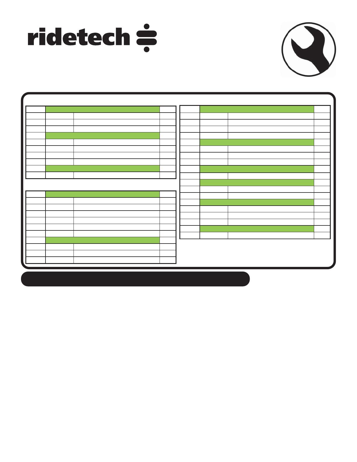
Hardware Shown in Diagrams .....Kit# 99010151
Getting Started.........
Congratulations on your purchase of the Ridetech TruTurn System. This System has been designed to give
your Chevy II excellent handling along with a lifetime of enjoyment. Some of the key features of the Tru-
Turn System: Ball joint angles have been optimized for the lowered ride height, eliminated rubber bushings
to get rid of bushing deflection and provide free suspension movement through the entire range of travel.
The geometry has been optimized for excellent handling, driveabilty and minimal bump steer.
Note: These control arms are designed for use with the Ridetech CoilOvers and the MuscleBar swaybar.
The factory shocks and springs or the factory sway bar will not fit these arms.
THE DRAGLINK ADAPTER IN THIS KIT IS DESIGNED FOR FACTORY STYLE FRONT SUMP OIL PANS.
IF YOU HAVE A REAR SUMP OIL PAN, YOU WILL NEED DRAGLINK ADAPTER #90003358.
Brake Kits
These spindles are designed around stock disc brake spindles and will accept any disc brake set up designed
for those. The only modification we discovered to be necessary, was a small trim on the bottom
of the stamped ¼” steel caliper bracket that holds the caliper. It is an area that is not stressed and
will not cause any loss of strength. Trim only enough to make the caliper bracket clear the spindle. If you
are using the factory dust shields, they will also require trimming. If your car came with drum brakes, be
sure to swap to the appropriate disc brake master cylinder and valving.
1. The shocks, coilsprings, control arms, tie rods, and sway bar need to be removed from the car.
Item # QTY
12 99311011 5/16Ͳ18 X 1 1/4" HEX CAP SCREW GR8 4
13 99313001 5/16" FLAT WASHER GR8 8
14 99312002 5/16Ͳ18 NYLON LOCKNUT GR8 4
15 99501021 1/2Ͳ20 X 2.75 HEX BOLT GR8 4
16 99503015 1/2" SPLIT LOCK WASHER GR8 4
17 99503014 1/2" SAE FLAT WASHER GR8 4
18 99502004 1/2Ͳ20 HEX NUT GR8 4
19 99502017 1/2Ͳ20 Castle Nut 2
Cross Shaft to Car
Shock Mount
Upper Ball Joint To Spindle
Item # QTY
49 99433002 7/16" SAE FLAT WASHER 2
50 99502010 1/2Ͳ20 MECHANICAL LOCK NUT 2
51 99432005 7/16Ͳ20 CASTLE NUT 2
99952002 3/32" COTTER PIN 2
51 99432005 7/16Ͳ20 CASTLE NUT 2
52 99622005 5/8Ͳ18 THIN MECHANICAL LOCK NUT 2
99952002 3/32" COTTER PIN 2
52 99622005 5/8Ͳ18 THIN MECHANICAL LOCK NUT 4
53 99800002 5/8Ͳ18 LH JAM NUT 2
54 99800003 5/8Ͳ18 RH JAM NUT 2
55 99501053 1/2Ͳ13 X 1.50 HEX BOLT GR 82
56 99502009 1/2Ͳ13 NYLON LOCKNUT GR8 2
57 99503014 1/2" SAE FLAT WASHER GR8 2
58 99501054 1/2Ͳ20 FLAT HEAD CAP SCREW 2
Inner Tie Rod Stud
Outer Tie Rod Stud
Tie Rod
Steering Stop
Steering Arm
Drag Link Stud
Kit# 99010187
Item # QTY
27 99431021 7/16Ͳ14 X 1.25" HEX BOLT GR8 16
28 99432010 7/16Ͳ14 NYLON LOCK NUT GR8 16
29 99433005 7/16" SAE FLAT WASHER GR8 32
30 99311011 5/16Ͳ18 X 1.25" HEX BOLT GR8 6
31 99312002 5/16Ͳ18NYLONLOCKNUTGR8 6
32 99313001 5/16" SAE FLAT WASHER GR8 12
33 99501016 1/2Ͳ20 X 4.00" HEX BOLT GR8 4
34 99502002 1/2Ͳ20NYLONLOCKNUTGR8 4
35 99503014 1/2"SAE FLAT WASHER GR8 8
Chassis Plate
Lower Control Arms Mounting
Kit# 99010188 Kit# 99010186
7812-482-2932
Installation
Instructions
Disassembly
2. The OEM strut rod mounts will need to be
removed form the car. The strut rod mount
is attached to the car with 4 rivets. There is a
5th rivet that attaches the radiator support to
the frame rail that will also need removed. We
have seen some cars that have a bolt/nut here
instead of a rivet.
3. We cut a “+” in the head of the rivets.
4. With the “+” cut in the head of the rivet,
chisel the head of the rivet off. The head of
the rivet should come off in 4 pieces.
REMOVE
RIVETS
2.
3.
4.
8
www.ridetech.com
Installation
Instructions
Disassembly
5. With the rivet heads removed, the strut rod
mount can be removed from the car.
6. The remainder of the rivets will need to be
removed from the frame of the car.
7. The crossmember will need to be removed
from the car. The crossmember will be
reinstalled later.
5.
7.
6.
9812-482-2932
Installation
Instructions
Installing Lower Control Arm Mount
Use Images 8 - 12 as a guide to install the
lower control arm mounts.
8. Image 8 shows the DRIVER lower control
arm mount. The lower control arm mounting
plate will attach to some of the OEM rivet holes.
The mounting holes that will use the OEM rivet
holes are pointed out with arrows in Image 8.
You may need to use a 7/16” drill bit to clean
up the rivet holes that will be used to attached
the lower control arm mounting plate. The (4)
crossmember mounting bolts will also line up
with the crossmember holes in the frame.
9. Align the lower control arm mount with the
OEM rivet holes. Install a 7/16” flat washer on
each of (4) 7/16”-14 x 1 1/4” bolts. Insert the
bolts/washers in the holes that align with the
OEM rivet holes. The threads of the bolts need
to be pointing up before final tightening. We
installed a few of the bolts with the threads
pointing down for alignment purposes. We
removed them and installed them with the
threads pointing up after we got some of the
other bolts installed correctly. Install a 7/16”
flat washer and 7/16”-14 nylok nut on each of
the bolts.
10. Use a 7/16” drill bit to drill the (4) holes in
the frame rail that don’t exist.
8.
9.
DRIVER
DRIVER
FRONT
10. DRIVER
10
www.ridetech.com
Installation
Instructions
Installing Lower Control Arm Mount
11. Install a 7/16” flat washer on each of
(4) 7/16”-14 x 1 1/4” bolts. Insert the bolts/
washers in the holes that align with the holes
that were just drilled. The threads of the bolts
need to be pointing up. Install a 7/16” flat
washer and 7/16”-14 nylok nut on each of the
bolts. Torque the bolts to 80 ft-lbs. Repeat
Step 8-12 on the other side.
13. The crossmember will need to be notched
to clear the lower control arm mount. Hold
the crossmember up in position to see where
you will need to notch it.
13. Image 13 shows the crossmember after it
as been notched.
13.
12.
11.
DRIVER
NOTCHES
11 812-482-2932
Installation
Instructions
Installing Crossmember & Lower Control Arm
14. Hold the crossmember in position, aligning
it with the mounting holes of the control arm
plate and frame. The kits includes new 5/16”
hardware to reattach the crossmember. Install
a 5/16” flat washer on each of (6) 5/16”-18 x 1
1/4” bolts. THE REAR INNER CROSSMEMBER
BOLT WILL NOT BE INSTALLED AT THIS TIME, IT
WILL BE INSTALLED WITH THE INSTALLATION
OF THE SWAY BAR. Insert the bolts/washers
in the (2) front holes and the rear outer holes.
With a bolt installed in each hole, install a
5/16” flat washer and 5/16”-18 nylok nut on
each of the bolts. Torque the hardware to 25
ft-lbs.
15. Image 15 is of the DRIVER lower arm as
viewed from the top.
16. Insert the lower control arm into the
mounts. The rear bushing goes into the OEM
mount. The front busing gets installed into the
mount on the new lower control arm plate.
Align the through hole of the bushing with the
slots in the mounts.
14.
15.
DRIVER
16.
12
www.ridetech.com
Installation
Instructions
Installing Lower Control Arm
17. Eccentric eliminator plates are included,
one must be installed on each side of the
frame. Start out with it in the center, make
sure both plates are in the same position. The
CENTERED position is shown in Image 17.
18. Install a 1/2” flat washer on each of (4)
1/2”-20 x 4” hex bolt. Insert the bolt in the
eccentric eliminator plate. Install the assembly
in the lower control arm mount. Repeat for
the 2nd bushing.
19. Install another eccentric eliminator on the
threads of the bolt. Make sure the plate is
orientated the same as the other plate. Install
a 1/2” flat washer and 1/2”-20 nylok nut on
the bolt. Repeat for the 2nd bushing. Torque
the hardware to 120 ft-lbs.
Repeat Steps 16-19 on the 2nd control arm.
19.
18.
17.
13 812-482-2932
Installation
Instructions
Installing Upper Control Arm
20. Image 20 is of the DRIVER upper arm as
viewed from the top.
21. The OEM upper control arm holes need to
be drilled out using a 1/2” drill bit.
22a. Steps 22a & 22b illustrate mounting the
upper control arm. The upper StrongArm gets
bolted to the body using ½”-20 x 2 ½” bolts
& flat washers. The ARROW points to the
front of the vehicle.
20.
21.
DRIVER
22a.
14
www.ridetech.com
Installation
Instructions
Installing Upper Control Arm & Spindle
22b. Hold the arm in place and install the bolt/
washers. Install a 1/2” split lock washer and
1/2”-20 nut on the threads of the bolts that
are sticking through the shock tower. Torque
the hardware to 110 ft-lbs.
23. Install the spindle on the upper ball joint
pin. Torque the ball joint castle nut to 50 ft-
lbs and tighten to align the cotter pin holes.
Install the cotter pin in the ball joint pin hole
and bend the ends of the cotter pin to hold it
in place. Install the grease zerk supplied with
the ball joint.
24. The spindles included in this kit are
identical for each side. They are not side
specific until the steering arm is attached.
Install the spindle on the lower ball joint pin.
Torque the ball joint castle nut to 65 ft-lbs and
tighten to align the cotter pin holes. Install the
cotter pin in the ball joint pin hole and bend
the ends of the cotter pin to hold it in place.
Install the grease zerk supplied with the ball
joint.
24.
23.
22b.
15 812-482-2932
Installation
Instructions
Spindle & Centerlink Adapter Installation
25. The SMALL tapered studs will get installed
into the factory centerlink with the taper going
into the centerlink, a 7/16” castle nut is used to
attach it to the centerlink. The straight shank
will point to the front of the car.
Note: It may be necessary to install 7/16”
washers under the castle nut to get the cotter
pin engaged properly.
26. Torque the nuts to 35 ft-lbs and tighten
as needed to align cotter pin. Install cotter pin
and bend the ends.
27. The centerlink bracket has one attachment
hole [A] that is slotted. This is to accommodate
the variations in manufacturing and machining
processes, as well as any wear that may have
occurred to the original centerlink over time.
The slot goes on the passenger side centerlink
adapter stud.
25.
26.
27.
A
TOP
16
www.ridetech.com
Installation
Instructions
Centerlink Adapter Installation
28. Install the draglink adapter on the studs
sticking out of the OEM draglink. Install a
1/2”-20 mechanical locking nut on the threads
of each stud sticking through the draglink
adapter. Torque the nuts to 50 ft-lbs.
29. The studs with the short hex get installed
into the centerlink adapter. The short side
goes into the adapter attached with the 5/8”-
18 thin top lock nut, with the long side of the
stud pointing forward.
30. Install the 5/8”-18 THIN mechanical
locking nut on the threads of the stud sticking
through the centerlink adapter and torque to
45 ft-lbs.
30.
29.
28.
17 812-482-2932
Installation
Instructions
Centerlink Adapter, Steering Arm & Stop Installation
31a. Install the steering arms and steering stops
onto the spindle using Images 31a & 31b as a
reference. The steering arms angle toward the
centerlink, and the tie rod mounting holes are
to the rear of the car. The steering stops are
marked D and P.
The steering arm is attached to the spindle
using ½”-20 x 2 ½” flat socket cap bolts and
nylok nuts. Torque to 100 ft-lbs.
The upper tab of the steering stop is attached
to the spindle using ½”-13 x 1 ½” hex head
bolt, 1/2” SAE flat washer, and Nylok. Torque
to 75 ftlbs.
31b. You will notice in Image 31b, the bottom
hole of the steering stop is mounted on top of
the front steering arm mounting hole. The
top mounting tab of the steering stop is on the
engine side of the spindle.
32. Install the stud with the round flange into
the steering arm with the taper going into the
steering arm. Torque the nuts to 35 ft-lbs and
tighten as needed to align cotter pin hole and
install cotter pin.
DRIVERPASSENGER
DRIVER
31a.
31b.
32.
18
www.ridetech.com
Installation
Instructions
Tie Rod Assembly & Installation
33. The tie rod adjuster has 2 threads in it; 5/8”-
18 RH & 5/8”-18 LH. The 5/8”-18 LH thread
is marked with a groove on the outside of the
adjuster. The tie rod can now be assembled to
a center to center length of 11 3/8” to start
with, having equal amount of threads on both
ends. These aluminum adjusters have a left
hand thread on one end and a right hand
thread on the other. You should use anti
seize when threading the heim ends into the
adjuster. FOR YOUR SAFETY, THE TIE ROD
& HEIM NEED A MINIMUM OF 15/16” OF
THREAD ENGAGEMENT INTO THE TIE ROD
ADJUSTER.
34. Install one end of the tie rod onto the stud
of the centerlink adapter.
35. Install the 5/8” ID x .125” spacer on the
stud followed by a 5/8”-18 mechanical locking
nut. Torque to 45 ft-lbs.
35.
34.
33.
19 812-482-2932
Installation
Instructions
Tie Rod Installation
36. Install a 5/8” ID x 3/8” spacer on the
steering arm stud, followed by the outer end
of the tie rod.
37. Install the 5/8” ID x .125” spacer on the
stud followed by a 5/8”-18 mechanical locking
nut. Torque to 45 ft-lbs.
36.
37.
Assembly...
Final Tightening & Alignment Specifications
38. Double check that you have tightened all hardware to the proper torque. If you are going to install the
Ridetech MuscleBar, now is a good time to do it.
Suggested Alignment Specs:
Camber: Street: -.5 degrees
Caster: Street: +3.0 to + 5.0 degrees
Toe: Street: 1/16” to 1/8” toe in
20
www.ridetech.com
Installation
Instructions
Assembly...
Torque Specifications
COMPONENTS TORQUE
LOWER CONTROL ARM MOUNT - 7/16”-14 80 FT-LBS
CROSSMEMBER MOUNTING 25 FT-LBS
FRONT UPPER SHOCK MOUNT TO FRAME 50 FT-LBS
LOWER CONTROL ARM MOUNTING 120 FT-LBS
UPPER BALL JOINT (tighten to align cotter pin hole after torquing) 50 FT-LBS
LOWER BALL JOINT (tighten to align cotter pin hole after torquing) 65 FT-LBS
CENTERLINK STUD NUT - 7/16”-20 35 FT-LBS
CENTERLINK ADAPTER TO STUD - 1/2”-20 50 FT-LBS
INNER TIE ROD STUD - 5/8”-18 45 FT-LBS
STEERING ARM TO SPINDLE 100 FT-LBS
STEERING STOP TO SPINDLE 75 IN-LBS
OUTER TIE ROD STUD - 7/16”-20 35 FT-LBS
INNER & OUTER TIE ROD MOUNTING - 5/8”-18 45 FT-LBS
  • Page 1 1
  • Page 2 2
  • Page 3 3
  • Page 4 4
  • Page 5 5
  • Page 6 6
  • Page 7 7
  • Page 8 8
  • Page 9 9
  • Page 10 10
  • Page 11 11
  • Page 12 12
  • Page 13 13
  • Page 14 14
  • Page 15 15
  • Page 16 16
  • Page 17 17
  • Page 18 18
  • Page 19 19
  • Page 20 20

Ridetech Front TruTurn System | 1962-1967 Chevy II / Nova Operating instructions

Type
Operating instructions
This manual is also suitable for

Ask a question and I''ll find the answer in the document

Finding information in a document is now easier with AI