TRAXXAS.com
Traxxas, 6250 Traxxas Way, TX 75070,
Phone: 972-549-3000, Fax: 972-549-3011, e-mail:
[email protected] KC2914-R01 Rev 2206139042*
9042X
2580*
3x20 BCS
9069
9038
9038G
9038R
9038T
9038X
9032
9032G
9032R
9032T
9032X
9037
9037G
9037R
9037T
9037X
2580*
3x20 BCS
3642X*
3x12 CCS
2579
3x15 BCS 2579
3x15 BCS
2577
3x10 BCS
5120A
12x18x4 BB
5117A
6x12x4 BB
5117
5120
3642X*
3x12 CCS
2577
3x10 BCS
2576
3x8 BCS
2576
3x8 BCS
9016
9043*
1
4
2
3
6
2579
3x15 BCS
5
6x9.5x0.5 PW
3981
9051
9057
9056 2754
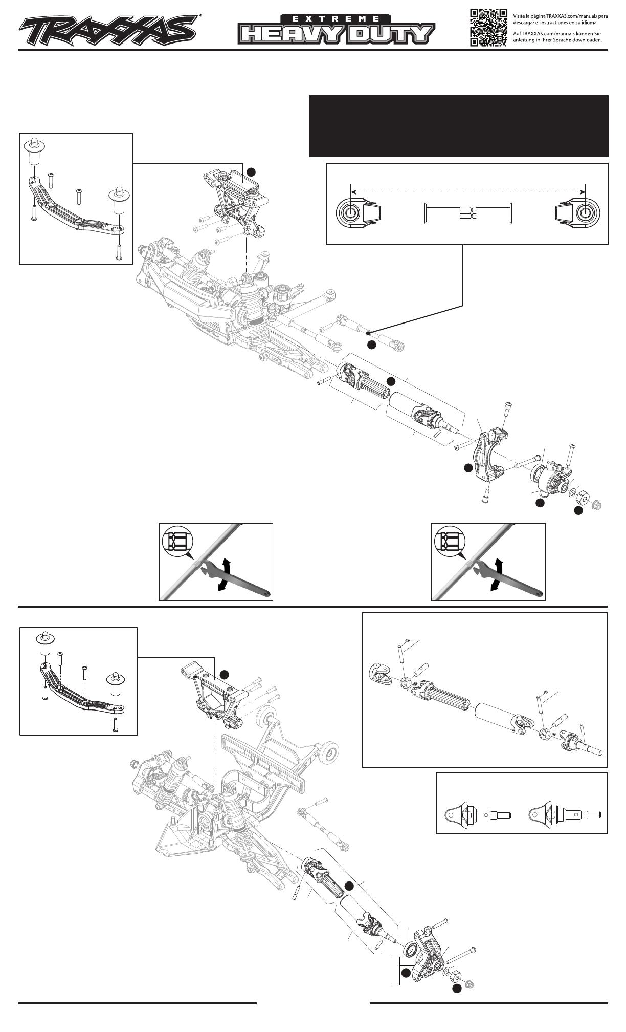
FRONT ASSEMBLY / JEU AVANT
Covers Parts #9080, 9080G, 9080R, 9080T, 9080X
Concerne les pièces #9080, 9080G, 9080R, 9080T, 9080X
Slash 4X4
Actual size / Taille réelle
81mm
TURNBUCKLE LENGTH* / LONGUEUR DU TENDEUR*
Outer Driveline & Suspension Upgrade Kit Installation Instructions /
Instructions d’installation de la trousse de mise à niveau de la
chaîne cinématique extérieure et de la suspension
Left Hand Thread Indicators
All of the turnbuckles on the truck should be
installed so the left hand thread indicators
point to the same direction. This makes it easier
to remember which way to turn the wrench
to increase or decrease turnbuckle length (the
direction is same at all four corners). Note that
the groove in the hex indicates the side of the
turnbuckle with the left-hand threads.
Indicateur de filetage à gauche
Tous les tendeurs du camion doivent être installés
de sorte que les indicateurs de filetage à gauche
soient orientés dans le même sens. Il est ainsi
plus facile de se rappeler dans quel sens tourner
la clé pour accroître ou décroître la longueur du
tendeur (le sens est le même à tous les quatre
coins). Notez que la rainure de l’écrou hexagonal
indique le côté du tendeur avec filetage à gauche.
Left Hand
Threads
Right Hand
(Normal) Threads
Decrease
Length
Increase
Length
96.75mm
Left Front
Wide diameter hollow ball
Front Toe Link - 5538, 5539X, 5595 (actual size)
Front Camber Link - 5539, 5539X, 5594 (actual size)
Rear Camber Link - 5539, 5539X, 5594 (actual size)
This end always mounts to the bulkhead.
85.40
Left Rear Wide diameter hollow ball
This end always mounts to the bulkhead.
Note: Camber links are factory assembled for front installation.
Adjust rear camber links to the appropriate length using template provided below.
86.90
Roscas a la
izquierda
Roscas a la
derecha (normal)
Disminuir
la longitud
Aumentar
la longitud
96.75mm
Left Front
Wide diameter hollow ball
Front Toe Link - 5538, 5539X, 5595 (actual size)
Front Camber Link - 5539, 5539X, 5594 (actual size)
Rear Camber Link - 5539, 5539X, 5594 (actual size)
This end always mounts to the bulkhead.
85.40
Left Rear Wide diameter hollow ball
This end always mounts to the bulkhead.
Note: Camber links are factory assembled for front installation.
Adjust rear camber links to the appropriate length using template provided below.
86.90
9016
2577
3x10 BCS
2576
3x8 BCS
2576
3x8 BCS
2579
3x15 BCS
9069
9042*
9042X
9052
2580*
3x20 BCS
9043*
5120A
12x18x4 BB
5117A
6x12x4 BB
5120
5117
1
2
3
2579
3x15 BCS
2577
3x10 BCS 2577
3x10 BCS
9039
9039G
9039R
9039T
9039X
4
2579
3x15 BCS
6x9.5x0.5 PW
3981
9057
9055
9050
9050G
9050R
9050T
9050X
2754
Slash 4X4
REAR ASSEMBLY / JEU ARRIÈRE
Installation
1.
Remove the wheel/tire and wheel hex.
2.
Remove the steering block.
3.
Remove the caster block (c-hub).
4.
Remove the driveshaft assembly.
5.
Adjust the camber link (turnbuckle) length to 81mm.
6.
Remove the shock tower.
7.
Repeat steps 1-5 for the other side.
8.
Installation of the parts is the reverse of removal.
Note: If using the #9051X front or 9052X rear accessory steel CV driveshafts,
#9053 front or 9054 rear heavy-duty stub axles are required (both sold
separately). The #6851R front and 6852R rear accessory steel CV driveshafts are
not compatible with the Extreme Heavy Duty Upgrade Kit.
*Use included hardware in these locations.
Installation
1.
Enlevez la roue/le pneu et l‘écrou hexagonale.
2.
Enlevez l’arrêtoir de la direction.
3.
Enlevez l’arrêtoir de la roulette (moyeu-c).
4.
Enlevez l’ensemble d’arbre d’entraînement.
5.
Ajustez la longueur de la biellette de carrossage (tendeur) à 81 mm.
6.
Enlevez la tour d’amortisseur.
7.
Répétez les étapes 1 à 5 pour l’autre côté.
8.
L’installation des pièces se fait dans l’ordre inverse de leur démontage.
Note : Si vous utilisez les arbres d’entraînement CV en acier pour accessoire n°9051X avant ou 9052X arrière, les porte-fusées à grande
résistance n°9053 avant ou 9054 arrière sont requis (les deux sont vendus séparément). Les arbres d’entraînement CV en acier pour
accessoire n°6851R avant et 6852R arrière ne sont pas compatibles avec le trousse de mise à niveau extrêmement renforcé.
* Utilisez le matériel inclus dans ces emplacements.
Installation
1.
Remove the wheel/tire and wheel hex.
2.
Remove the stub axle carrier.
3.
Remove the driveshaft assembly.
4.
Remove the shock tower.
5.
Repeat steps 1-3 for the other side.
6.
Installation of the parts is the reverse of removal.
*Use included hardware in these locations.
Installation
1.
Enlevez la roue/le pneu et l‘écrou hexagonal.
2.
Enlevez le support de porte-fusée.
3.
Enlevez l’ensemble d’arbre d’entraînement.
4.
Enlevez la tour d’amortisseur.
5.
Répétez les étapes 1 à 3 pour l’autre côté.
6.
L’installation des pièces se fait dans l’ordre inverse de leur démontage.
* Utilisez le matériel inclus dans ces emplacements.
Note: The Extreme Heavy Duty Upgrade Kit must be used in its entirety and is not
compatible with some existing Traxxas replacement or upgrade parts.
Note : Le trousse de mise à niveau extrêmement renforcé doit être utilisé dans son
intégralité. Il n’est pas compatible avec certaines pièces de rechange ou de mise à
niveau Traxxas existantes.
5452
9056
5452
5452
5452
5452
5452
5452
9055
9056
9055
9057
9057
5452
9056
5452
5452
5452
5452
5452
5452
9055
9056
9055
9057
9057
STUB AXLES / PORTE FUSÉES
Rear / ArrièreFront / Avant
FRONT & REAR DRIVESHAFT ASSEMBLY /
ENSEMBLE D’ARBRE D’ENTRAÎNEMENT AVANT ET ARRIÈRE
