Page is loading ...

Operation Manual
Back-UPS
™
Pro
Uninterruptible Power Supply
BG500 120 Vac


Back-UPS Pro 500 BG500 120 Vac 1
Overview
Product Description
The APC
™
by Schneider Electric Back-UPS
™
Pro BG500 is a high performance Lithium Ion uninterruptible
power supply (UPS). It provides protection for electronic equipment from AC power blackouts, brownouts, sags,
and surges, small AC fluctuations and large disturbances. The UPS also provides battery backup power for
connected equipment until AC power returns to safe levels or the batteries are fully discharged.
Safety and General Information
Inspect the package contents upon receipt. Notify the carrier and dealer if there is any
damage.
Read the Safety Guide supplied with this unit before installing the UPS.
• This UPS is intended for indoor use only.
• Do not operate this UPS in direct sunlight, in contact with fluids, or where there is excessive dust or
humidity.
• The battery typically lasts for six to ten years. Environmental factors impact battery life. Elevated ambient
temperatures, poor quality AC power, and frequent short duration discharges will shorten battery life.
• Connect the UPS power cable directly to a wall outlet. Do not use surge protectors or extension cords.
• Before installing or replacing the batteries, remove jewelry such as wrist watches and rings. High short
circuit current through conductive materials could cause severe burns.
Specifications
For additional specifications, refer to the APC by Schneider Electric Web site at
www.apc.com.
Model
BG500
VA 500 VA
Maximum Load
300 W
Nominal Input Voltage
120 Vac
Green Standard Mode Power Consumption
0.86 W
Online Input Voltage Range
Default Setting: 92 V - 139 V
Low Sensitivity Setting: 88 V - 142V
High Sensitivity Setting: 96 V - 136 V
Frequency Range
50 Hz - 60 Hz auto sensing
Total Amperage (all outlets)
4.2 A (including UPS output)
Voltage - On Battery
115 Vrms ± 8% quasi sine wave
Frequency - On Battery
50 Hz/60 Hz ± 1 Hz
Typical Recharge Time
12 hours
Transfer Time
10 ms, maximum
Operating Temperature
10 to 40C (50 to 104F)
Storage Temperature
-15 to 45C (5 to 113F)
Unit Dimensions
29 × 19.1 x 5.4 cm (11.42 × 7.52 x 2.13 in)

Back-UPS Pro 500 BG500 120 Vac2
Battery Replacement
Always recycle used batteries.
For information on recycling a used battery, refer to the Battery Disposal
Information sheet included with the replacement battery.
Replace used batteries with APC approved batteries. To order a replacement battery go to the APC by Schneider
Electric Web site, www.apc.com.
Unit Weight 2.2 kg (4.85 lbs)
Interface Web page
On Battery Runtime
Go to: www.apc.com
Battery Capacity
2.3 Ah
Battery Voltage
13.2 V typical
Battery Output Current
40A continuous
Battery Weight
0.53 kg (1.17 lbs)
Battery Dimensions
7.74 x 15.23 x 4.16 cm (3.05 x 6 x 1.64 in)
Supported OS
Windows XP, Windows Vista, Windows 7, Windows 8 and Mac OS X
(USB)
Windows XP, Windows Vista, Windows 7 (software)
EMI Compliance
This equipment has been tested and found to comply with the limits for a
Class B digital device, pursuant to part 15 of the FCC Rules. These limits
are designed to provide reasonable protection against harmful interference
in a residential installation. This equipment generates, uses and can radiate
radio frequency energy and, if not installed and used in accordance with
the instructions, may cause harmful interference to radio communications.
However, there is no guarantee that interference will not occur in a
particular installation. If this equipment does cause harmful interference to
radio or television reception, which can be determined by turning the
equipment off and on, the user is encouraged to try to correct the
interference by one or more of the following measures:
– Reorient or relocate the receiving antenna.
– Increase the separation between the equipment and receiver.
– Connect the equipment into an outlet on a circuit different from
that to which the receiver is connected.
– Consult the dealer or an experienced radio/TV technician for help.
Notice: This device complies with part 68 and part 15 of the FCC rules.
Operation is subject to the following two conditions:
(1) This device may not cause harmful interference, and
(2) This device must accept any interference received, including
interference that may cause undesired operation.
“Locate the label on the bottom of this device that contains, among other
information, the FCC registration number and ringer equivalence number
(REN) for this device. If requested, this information must be provided to
the telephone company.”
USB Compliance
USB-If Basic Speed
UPS Model Replacement Battery
BG500 APCRBC146-LI
Li-ion

Back-UPS Pro 500 BG500 120 Vac 3
Lithium Ion Battery Safety Information
This product uses a lithium ion battery.
The following safety rules must be followed when shipping the battery by air transportation.
1. Disconnect the battery and remove it from the UPS.
2. Do not pack more than two batteries in the same box.
3. Place the lithium ion battery handling label with power rating in watts, on the box if two batteries are
packaged in one box. Detailed battery specifications are listed above.
4. The following information must be included on the Air Waybill:
a. Lithium ion batteries or cells, NOT RESTRICTED as per PI966 Part 1.
b. Handle the package with care!
Damage to the batteries can cause a fire hazard or the batteries may short circuit.
c. Contact telephone number
5. Contact the air cargo company for more detailed shipping information.

Back-UPS Pro 500 BG500 120 Vac4
Operation
Product Overview
Front panel features
Rear panel features
Power On/Off button - The Back-UPS is supplying conditioned AC power to connected equipment
Network Status - The Back-UPS is connected to the Ethernet network.
Energy Management - Master and Smart outlets are enabled, saving power when the master device goes
into sleep or standby mode
Watchdog - The Watchdog function is enabled on one or both Smart outlets
Replace Battery - The battery is not connected or is nearing the end of its useful life. Replace the battery.
Backup
Outlets
These outlets provide full-time surge
protection for connected equipment from
power surges even when the Back-UPS is
turned off. Both outlets also have full time
battery backup.
Smart
Outlets
These outlets also provide full-time surge
protection for connected devices. Smart
Outlets are remotely manageable and can
configurable.
•Energy Management: To conserve energy
the Smart outlet 1 and 2 will disconnect
from AC power whenever the device
plugged into the MASTER outlet is turned
off or goes into Standby or Hibernation
mode. Connect a printer, scanner or other
noncritical devices that do not require
battery backup protection.
•Watchdog: The Watchdog feature
automatically restarts networking gear
when a loss of internet connectivity is
detected. Suggested devices for connection
to Smart Outlet 1 is a modem, and a
wireless router for Smart Outlet 2.
Combined wireless modem and router
should be plugged into Outlet 1. The UPS
will ping the configured remote IP address
and if there is a failure for the duration of
the test interval, the UPS will reboot the
devices plugged into the Smart Outlets
sequentially.
•Configurable Backup: These
configurable outlets can be configured as
“Yes” or “No” in the device's web interface.
When set to “No”, these configurable
outlets do not provide battery backup to
connected equipment. Connect a printer,
scanner or other noncritical devices that do
not require battery backup protection.
b
u
2
5
6
b
bu253d

Back-UPS Pro 500 BG500 120 Vac 5
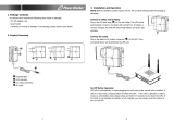
Installation
UPS
For UPS installation instructions, refer to the Back-UPS Pro BG500 Installation Guide that is supplied
with the UPS. The guide is also available on the enclosed User Manual CD and the APC by Schneider
Electric Web, site at www.apc.com.
Energy Management
Energy Management function can be used to automatically reduce energy consumption. Plug your
computer into the Master outlet, and when it is turned OFF or goes into “sleep”, “standby”,
“hibernation” mode, any peripherals plugged into the Smart Outlets like speakers, scanners, modem, router or
printers, will also shut off automatically, eliminating needless electricity waste.
Notes: The Back-UPS ships with this Energy Management feature DISABLED. If you wish to use this feature,
follow the instructions below.
Enable and Disable the Energy Management function. The Energy Management function of the Back-
UPS can be toggled between Enable and Disable through the Web page. Once enabled, the leaf indicator on the
front panel will illuminate and extinguish once disabled. Refer to the "Web based Management Interface" on
page 22 for instructions on how to access the Web page.
Watchdog Introduction
The Watchdog function is a feature for monitoring network equipment and automatically rebooting it
when it looses connectivity to the internet. In many cases when networking equipment loses
connectivity a quick reboot is usually the fastest way to resolve the issue. With the BG500 this can be done
automatically. The way it works is simple. Connect BG500 to your internet router using an Ethernet cable. Plug
both your modem and wireless router to the Smart Outlets on the Back-UPS Pro. When configured properly the
Back-UPS Pro will ping an IP address outside your network on the internet. When the Back-UPS Pro is not able to
connect to that IP address it will reboot the modem and the router in an attempt to resolve the problem. No further
user intervention is required. For more details follow the instructions in the Watchdog Settings on page 38 of this
manual.
Master outlet Connect the master device to this outlet, in most cases, this will be the main computer.
In addition to providing battery backup power and surge protection, this outlet will signal the Smart outlet to disconnect from
AC power when the master device is either turned off or goes into Standby, Sleep, or Hibernation mode.
Telephone Surge
Protection
The Back-UPS protects equipment connected to a telephone line from power surges when connected through the Back-UPS
telephone cable connectors.
Mini USB port Use to connect the system to the desktop PC in order to monitor the Back-UPS battery condition.
Circuit breaker Use to reset the system after an overload condition has occurred causing the circuit breaker to trip
Building Wiring
Fault indicator
The LED illuminates when there is no ground circuit, a neutral overload, or there is a reversed polarity in the building wiring.
Protection is not guaranteed when the LED is illuminated. Have a qualified electrician correct the building wiring.
Network Reset
button
Use to reset UPS by pressing for more than 20 seconds, all network configuration and login information will be set to factory
default when pressed for less than 20 seconds, it will reboot the network connection.
Network
Management
port
Use an Ethernet cable to connect a computer, modem or a router to this port. This port allows for the UPS to be managed
remotely via a web based user interface.

Back-UPS Pro 500 BG500 120 Vac6
Connect Equipment
Connect a master device, such as a desktop computer or audio/visual receiver to the Master outlet. Connect
peripheral devices such as a printer, speakers, or a scanner to the Smart Outlets.
Other required installations for the Back-UPS to function properly include Ethernet cable connection, Telephone
Protection In/Out connection, and battery pack installation.
Note: The UPS will charge to 90% capacity in the first three hours of normal operation. Do not
expect full battery runtime capability during this initial charge period.
1. Connect equipment to the outlets on the rear panel of the UPS.
Refer to "Smart Outlets" on page 20.
2. Connect the UPS to the building AC power. Connect the UPS to a two-pole, three-wire, grounded
source only.
3. To use the UPS as a
MASTER ON/OFF switch, turn on equipment that is connected to the UPS.
4. To turn on the UPS and all connected equipment. Press the
ON/OFF button on the front panel of the UPS.
5. Follow the prompts to configure the UPS using the set up wizard the first time the UPS is turned on. Refer
to "Network Quick Configuration" on page 22.
Backup and Smart outlets
When the Back-UPS is receiving input power, all outlets, Master, Backup and both Smart Outlets will supply
power to connected equipment.
During a power outage or other AC problems, all outlets should be supplying backup power to each outlet. Smart
Outlets can be configured to turn off outlets or be configured to be surge only. Here are the scenarios where a Smart
Outlet is not supplying backup power or is off.
a. User has remotely turned off Smart Outlet
b. Energy Management has been enabled and the load on the Master Outlet is below the threshold
where Energy Managed Smart Outlets are turned off.
c. The Watchdog feature has been enabled and a loss of network connectivity has been detected and the
Smart Outlet is temporarily off as part of the reboot process.
d. The Smart Outlet has been configured to not provide Backup power and is in a surge only
configuration.

Back-UPS Pro 500 BG500 120 Vac 7
Connecting the UPS by USB
By connecting the UPS to a computer by USB the operating system (Windows XP, Vista, 7, and 8 and Mac OS X) is
able to view the UPS as a battery and is able to display charge capacity and charge state (on AC or on battery). Use
the included cable to connect the USB cable on the back of the unit to an standard Type A USB port. The system
should recognize the battery automatically. No additional software is needed. If the system previously had
PowerChute Personal Edition (PCPE) installed there may be some driver conflict and users may have to make
adjustments to the system in order for the operating system to properly recognize the UPS
Connecting by OS
Mac OS X
Turn on the UPS, connect the UPS to the Mac computer using the supplied USB cable.
1.Click System Preferences icon along the Dock.
Click Energy Saver icon, you should see a UPS tab
displayed in the dialog.
Click UPS tab, check Show UPS status in the menu bar
option. The Mac OS X will then display a UPS icon in the
menu bar.
bu304a
bu305a
bu306a
bu307a

Back-UPS Pro 500 BG500 120 Vac8
Windows 7
Turn on UPS and connect UPS to the Windows 7 computer
via a USB cable. Click Start --> Control Panel -->
Hardware and Sound. Under Devices and Printers group,
click Device Manager. In the Device Manager window the
UPS is listed as a HID UPS Battery device.
If the UPS is installed as a HID UPS Battery device,
Windows 7 will display an UPS icon in the taskbar.
If the UPS is listed as an APC UPS Device. refer to step 3
in updating the device driver into HID UPS Battery.
Otherwise proceed to step 4.
Updating the driver from APC UPS to HID UPS Battery
Figure B
Figure C
3.1 If device manager shows APC UPS device or APC
Battery BackUP and in Power Options you cannot
configure the system to shutdown when the UPS is on
battery (Figures A - C) you have 2 options. 1 is to roll the
driver back to HID UPS (Figures D, E and K) or 2 is to
update the driver to HID UPS (Figures F - K)
As you see when APC UPS (figure A) or APC Battery
BackUP (Figure B) are the loaded driver under Power
Options (Figure C) there is no availability to configure
shutdown while on battery.
Figure A
bu310a
bu312a
bu281a
bu311a
bu318a
bu325a

Back-UPS Pro 500 BG500 120 Vac 9
Figure D Figure E
3.2 Option 1 - To roll the driver back: Go to Control Panel – Device Manager – Batteries – Select the APC UPS or APC
Battery BackUP – Select Driver tab – select Roll Back Driver. The Driver will revert to HID UPS (Figures D & E).
Figure F Figure G
Figure H
3.3 Option 2 – If you cannot roll the driver back (roll back is
grayed out) select Update Driver (Figure F) – Browse my
Computer for Driver Software (Figure G) – Select Let me Pick
from List of Device Driver on my Computer (Figure H) select
HID UPS from list (Figure I)
bu319a
bu324a
bu313a
bu338a
bu339a

Back-UPS Pro 500 BG500 120 Vac10
Figure I Figure J
Figure K
3.4 You can now configure Power Options to shutdown
when UPS is on Battery.
If the battery icon is not displayed in the system tray,
click Control Panel, click Appearance and
Personalization. Under the Taskbar and Start Menu group
click Customize icons on the taskbar.
Then click Turn system icons on or off.
Click the dropdown box for the Power system icon, select
On from the list. Now Windows should display the battery
icon in the system tray
.
bu340a
bu341a
bu342a
bu314a
bu315a

Back-UPS Pro 500 BG500 120 Vac 11
Windows XP
1.Turn on UPS and connect UPS to the Windows XP computer via a USB cable.
Click Start --> Setting --> Control Panel --> System. In
the System Properties window click the Hardware tab,
then click Hardware Manager button.
In the Device Manager window, expand Batteries. There
should be a HID UPS Battery listing under Battery. Then
you can skip following steps. If you see an APC UPS
device instead of a HID UPS Battery device. You need to
update the driver of UPS to the driver of HID UPS
Battery
Updating the driver from APC UPS to HID UPS
Battery
4.1 Double click the APC UPS device. 4.2 From the Driver tab, click on the Update Driver
button
bu323a
bu324a
bu325a
bu326a

Back-UPS Pro 500 BG500 120 Vac12
4.3 In the Hardware Update Wizard window, select Install
from a list or specific location (Advanced), then click
Next button.
4.4 In the Hardware Update Wizard – Please choose your
search and installation options window, select Don’t
search. I will choose the driver to install, then click the
Next button.
4.5 In the Hardware Update Wizard – Select the device
driver you want to install for this hardware. Choose HID
UPS Battery, then click Next button.
4.6 In the Hardware Update Wizard – Completing the
Hardware Update Wizard window, click Finish button.
bu327a
bu328a
bu329a
bu330a

Back-UPS Pro 500 BG500 120 Vac 13
4.7 After completing above steps, Window XP will return
to the HID UPS Battery Properties window. Click Close to
finish updating driver.
If the UPS is powered by AC source, Windows XP will
not display an icon on the taskbar by default. You can
change this behavior by clicking Start --> Setting -->
Control Panel --> Power Options. In the Power Options
Properties window, select Advanced tab, the check
Always show icon on the taskbar.
Windows XP will display an icon in the taskbar.
If UPS is powered by AC source.
If UPS is powered by battery.
bu331a
bu332a
bu333a
bu334a

Back-UPS Pro 500 BG500 120 Vac14
Configuring PC Shutdown
Make sure the battery icon on the previous section is already present on the system tray / task bar of your operating
system before proceeding to configuring the PC shutdown.
Mac OS X
Turn on the UPS, connect the UPS to the Mac computer using the supplied USB cable.
1.Click System Preferences icon along the Dock.
Click Energy Saver icon, you should see a UPS tab
displayed in the dialog.
Click UPS tab, check Show UPS status in the menu bar
option. The Mac OS X will then display a UPS icon in the
menu bar.
To configure the shutdown options, click on the
Shutdown Options button.
After configuring the shutdown options, click Done.
bu304a
bu305a
bu306a
bu307a
bu308a
bu309a

Back-UPS Pro 500 BG500 120 Vac 15
Windows 7
Right click the battery icon, select Power Options.
On the Select a power plan page, next to the plan you
want to change, click Change plan settings.
On the Change settings for the plan page, click Change
advanced power settings.
On the Advanced settings tab, expand Battery, expand
Low battery level, Reserve battery level, and Critical
battery level. Change the percentage of battery remaining
that you want for each level, and then click OK.
To configure the Windows 7 to shutdown itself, expand
Critical battery action. From the drop down box next to On
battery item, select Hibernate or Shutdown, and click OK
button to save the settings. Then Windows will hibernate
or shutdown itself when the percentage of battery
remaining drops below the configured critical level.
bu316a
bu317a
bu320a
bu321a
bu322a

Back-UPS Pro 500 BG500 120 Vac16
Windows XP
1. Turn on UPS and connect UPS to the Windows XP computer via a USB cable.
Windows XP will display an icon in the taskbar.
If UPS is powered by AC source:
If UPS is powered by battery:
In the Power Options Properties window, select Alarms
tab. In the Critical battery alarm pane, check Activate
critical battery alarm when the power level reaches:
option, change the percentage of battery remaining that
you want for critical battery level. Then click Alarm
Action button.
In the Critical Battery Alarm Actions window, check
When the alarm goes off, the computer will option, the
select Hibernate or Shutdown from the drop down box.
Also check Force stand by or shutdown even if a program
stops responding, then click OK button to close the
window.
After returning to Power Options Properties window,
click OK button to apply the settings.
bu333a
bu334a
bu335a
bu336a
bu337a

Back-UPS Pro 500 BG500 120 Vac 17
Display Interface
Status Indicators
Status LED Indicator
Audible
Indicator On
Audible Indicator
Terminates
Power On
The Back-UPS is supplying AC power to
connected equipment.
The green LED
illuminates.
None N/A
On Battery
Back-UPS supplying battery power to battery
backup outlets.
Default:
The green LED
illuminates but is
not illuminated
during the beeps
Default:
Back-UPS beeps
4 times every 30
seconds.
Default:
Beeping stops when AC
power is restored or the
Back-UPS is turned off.
The green LED
illuminates. The
LED flashes once
every 2 seconds
Back-UPS beeps
for 2 seconds
when entering
battery mode.
Beeping stops at the end of
the first two seconds. A
constant beep at the initial
two seconds indicates the
Back-UPS has entered the
battery mode.
Low Battery warning
The Back-UPS is supplying battery power to the
battery backup outlets and the battery is near a
total discharge state.
The green LED
illuminates with
rapid green flashes
every 1/2 second.
The Back-UPS
emits rapid
beeping every 1/
2 second.
Beeping stops when AC
power is restored or the
Back-UPS is turned off.
Battery Disconnected
The battery is disconnected or an unknown
battery pack is connected to the Back-UPS
The green LED
illuminates and the
LED flashes
red.
Constant tone
Back-UPS is turned off. or
battery is re-connected
Unrecognized Battery Alarm
While on AC power the Back-UPS cannot
identify the non-APC battery in the Back-UPS
The and LEDs
illuminate green/red
Constant tone
•Back-UPS is turned off
•When APC approved
battery pack APCRBC146-
LI is used
Unrecognized Battery Shutdown
While on power outage, the Back-UPS shuts
down completely due to an unknown battery
connected to the Back-UPS
The red LED
illuminates.
Constant tone
•Back-UPS is turned off
•When APC approved
battery pack APCRBC146-
LI is used
Replace Battery
The battery needs to be replaced.
The green and
red LEDs illuminate
alternately
Constant tone Back-UPS is turned off.
Network Status
When Back-UPS is connected to the Ethernet
network with 100M speed
The flashes green. None None
When Back-UPS is connected to the Ethernet
network with 10M speed
The flashes orange. None None
Energy Management
When Master Control Mode is enabled
The LED illuminates. None
When Master Control Mode
is disabled
Watchdog
When any Watchdog is enabled
The LED illuminates. None
When Watchdog is disabled
on both outlets
Overload Shutdown
An overload condition has occurred in one or
more of the battery backup outlets while the
Back-UPS is operating on battery power.
None Constant tone Back-UPS is turned off.

Back-UPS Pro 500 BG500 120 Vac18
Overload Alarm
While on AC power the online power exceeds
the Back-UPS capacity.
The green LED
illuminates.
Constant tone
Beeping stops when
equipment power plugs are
moved from battery backup
outlets to surge protection
outlets.
Sleep Mode
While on battery power, the battery is
completely discharged. The Back-UPS will
“awaken” once AC power is restored.
None
The Back-UPS
beeps once
every four
seconds.
Beeping stops when:
• AC power is restored
• If AC power is not restored
within 32 seconds
• The Back-UPS is turned off
Building Wiring Fault
The building wiring presents a shock hazard that
must be corrected by a qualified electrical.
Building Wiring Fault LED
at the rear panel illuminates
red
None
The Back-UPS is unplugged
from the wall outlet or is
plugged into an improperly
wired outlet.
Status LED Indicator
Audible
Indicator On
Audible Indicator
Terminates
/