Page is loading ...
Page is loading ...
Page is loading ...
Page is loading ...
Page is loading ...
Page is loading ...
Page is loading ...
Page is loading ...
Page is loading ...
Page is loading ...
Page is loading ...
Page is loading ...
Page is loading ...

Operating Instructions
TEP 649 L
Contents
Installation, 15-18
Positioning
Electrical connection
Gas connection
Burner and nozzle specifications
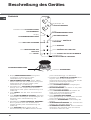
Description of the appliance, 19
Control panel
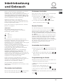
Start-up and use, 20-22
Switching on the hob
Switching on the cooking zones
Booster function
Switching off the cooking zones
Programming the cooking duration
Control panel lock
Switching off the hob
Practical advice on using the appliance
Practical advice on using the burners
Safety devices
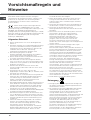
Precautions and tips, 23
General safety
Disposal
Care and maintenance, 24
Switching the appliance off
Cleaning the appliance
Disassembling the hob
Gas valve maintenance
Technical description of the models, 25
Troubleshooting, 26
HOB
GB
Italiano, 1
GB
Français, 27
Deutsch, 53Nederlands,
40
English,14
IT FR
DENL

15
GB
Before operating your new appliance please read this
instruction booklet carefully. It contains important
information concerning the safe operation, installation
and maintenance of the appliance.
Please keep these operating instructions for future
reference. Pass them on to any new owners of the
appliance.
Positioning
Keep all packaging material out of the reach of
children. It may present a choking or suffocation hazard
(see Precautions and tips).
The appliance must be installed by a qualified
professional in accordance with the instructions
provided. Incorrect installation may damage property or
cause harm to people or
animals.
The appliance may only be installed in permanently-
ventilated rooms, in accordance with current national
regulations. The following requirements must be
observed:
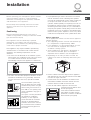
The room must be fitted with an air extraction system
which expels any combustion fumes. This may consist
of a cooker hood or an electric fan which starts
automatically every time the appliance is switched on.
The room must also allow proper air circulation, as air is
needed for combustion to occur normally. The flow of
air must not be less than 2 m
3
/h per kW of installed
power.
The air circulation system may
take air directly from the outside
environment by means of a pipe
with an inner cross section of at
least 100 cm
2
; the opening must
not be vulnerable to any type of
blockages.
The system can also provide the
air needed for combustion
indirectly, i.e. from adjacent
rooms fitted with air circulation
ducting as described above.
However, these rooms must not
be communal rooms, bedrooms
or rooms which may present a
fire hazard.
Liquid petroleum gas sinks to the floor as it is heavier
than air. Therefore, rooms containing LPG cylinders
must also be equipped with vents in order to allow gas
to escape in the event of a leak. As a result LPG
cylinders, whether partially or completely full, must not
be installed or stored in rooms or storage areas which
are below ground level (cellars, etc.). It is advisable to
keep only the cylinder currently being used in the room,
positioned so that it is not subject to heat produced by
external sources (ovens, fireplaces, stoves, etc.) which
could raise the temperature of the cylinder above 50°C.
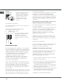
Built-in appliance
Use an appropriate cabinet to ensure that the appliance
operates properly.
The supporting surface must be heat-resistant up
to a temperature of approximately 100°C.
If the appliance is to be installed above an oven,
the oven must be equipped with a forced
ventilation cooling system.
Avoid installing the hob above a dishwasher: if
this cannot be avoided, place a waterproof
separation device between the two appliances.
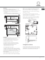
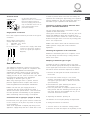
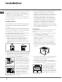
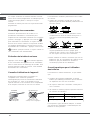
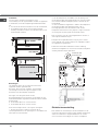
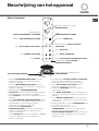
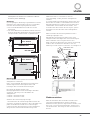
Depending on the hob you want to install, the
cabinet must have the following dimensions (see
figure):
Kitchen cabinets which are adjacent to the appliance
and taller than the top of the hob must be at least 600
mm from the edge of the hob.
Cooker hoods must be installed in accordance with
their relative installation instruction manuals and at a
minimum distance of 650 mm from the hob.
Place the wall cabinets adjacent to the hood at a
minimum height of 420 mm from
the hob (see figure).
If the hob is installed beneath a
wall cabinet, the latter must be
positioned a minimum of 700 mm
above the hob (see figure).
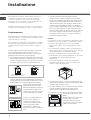
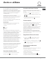
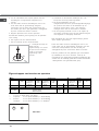
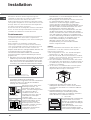
Installation
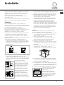
Enlarging the ventilation slot
between window and floor.
Adjacent
Room
Room to be
Vented
A
Examples of ventilation holes
for comburant air.
In a chimney stack or branched flue.
(exclusively for cooking appliances)
Directly to
the Outside
600mm min.
540mm min.
700mm min.
560 +/- 1
490 +/- 1
48
5
9
0
520

16
GB
supporting surface.
The screws for the alignment springs must remain
accessible.
In order to adhere to safety standards, the appliance
must not come into contact with electrical parts once it
has been installed.
All parts that ensure the safe operation of the appliance
must not be removable
without the aid of a tool.
Electrical connection
The electrical connections of the hob and any built-in
oven must be carried out separately, both for safety
purposes and to make extracting the oven easier.
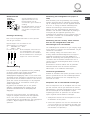
5 mm
min. 20 mm
min. 20 mm
min. 40 mm
COMPARTMENT
5 mm
min. 40 mm
FAN-ASSISTED
OVEN
FRONT SIDE
OF HOB
SUPPORTING
SURFACE
30
40
UNDERSIDE
OF HOB
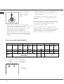
Ventilation
To allow adequate ventilation and to avoid overheating
of the surrounding surfaces the hob should be positioned
as follows:
At a minimum of 40 mm from the back panel.
So that a distance of at least 20 mm is maintained
between the installation cavity and the cabinet
underneath.
Fixing
The appliance must be installed on a perfectly level
supporting surface.
Any deformities caused by improper fixing could affect
the features and operation of the hob.
The thickness of the supporting surface should be taken
into account when choosing screws for the fixing hooks:
30 mm thick: 23 mm screws.
40 mm thick: 13 mm screws.
Fix the hob as follows:
1. Use short, flat-bottomed screws to fix the 4 alignment
springs in the holes provided at the central point of each
side of the hob.
2. Place the hob in the cavity, make sure it is in
a central
position and push down on the whole perimeter until the
hob is stuck to the supporting surface.
3. For hobs with raised sides: After inserting the hob into
its cavity, insert the 4 fixing hooks (each has its own pin)
into the lower edges of the hob, using
the long pointed
screws to fix them in place, until the glass is stuck to the

17
GB
in order to prevent leaks. The seal must always be
replaced after rotating the pipe fitting (seal supplied
with the appliance). The gas supply pipe fitting is a
threaded 1/2 gas cylindrical male attachment.
Connecting a flexible jointless stainless steel
pipe to a threaded attachment
The gas supply pipe fitting is a threaded 1/2 gas
cylindrical male attachment.
These pipes must be installed so that they are never
longer than 2000 mm when fully extended. Once
connection has been carried out, make sure that the
flexible metal pipe does not touch any moving parts
and is not compressed.
Make sure that the hose and the aluminium and
rubber gaskets comply with current national
regulations .
Checking the tightness of the
connection
When the installation process is complete, check
the pipe fittings for leaks using a soapy solution.
Never use a flame.
Adapting to different types of gas
To adapt the hob to a different type of gas other
than the default type (indicated by the label placed
on the upper part of the hob or on the packaging),
the burner nozzles should be replaced as follows:
1. Remove the hob grids and slide the burners off
their seats.
2.Unscrew the nozzles using a 7 mm socket
spanner, and replace them with nozzles for the
new type of gas (see table 1 Burner and nozzle
specifications).
3. Reassemble the parts following the above
procedure in the reverse order.
4. Once this procedure is complete, replace the old
rating sticker with one indicating the new type of
gas used. Stickers are available from any of our
Technical Assistance Centres.
Adjusting the burners primary air
The burners do not require primary air adjustment.
Setting the burners to minimum
1.Turn the valve to the minimum setting position.
2. Remove the knob and adjust the regulatory screw,
Blue
Brown
N
Neutral
L
Live
Green/Yellow
Earth
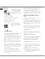
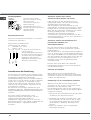
UNDERSIDE OF HOB
Terminal board
On the lower part of the
appliance there is a connection
box for the different types of
electricity supply (the picture is
only an indication and is not an
exact representation of the
purchased model).
Single-phase connection
The cable supplied should only be used for this type of
installation.
Mains supply characteristics:
Voltage and mains frequency
220-240 V 1+N ~ 50 Hz
230 V 2 ~ 50 Hz
If the hob has a supply cable fitted,
connect it to the mains, using the
colours as a guide (see adjacent
diagram).
Gas connection
The appliance should be connected to the mains
gas supply or to a gas cylinder in compliance with
current national regulations and subsequent
amendments. Before carrying out the connection,
make sure the cooker is compatible with the gas
supply you wish to use. If this is not the case, follow
the instructions indicated in the paragraph
Adapting to different types of gas.
When using liquid gas from a cylinder, install a
pressure regulator which complies with current
national regulations and subsequent amendments.
Make sure that the gas supply pressure is
consistent with the values indicated in Table 1,
Burner and nozzle specifications. This will ensure
the safe operation and durability of your appliance
while maintaining efficient energy consumption.
Connection with a rigid pipe (copper or steel)
Connection to the gas system must be carried out
in such a way as not to place any strain of any kind
on the appliance.
There is an adjustable L-shaped pipe fitting on the
appliance supply ramp and this is fitted with a seal

18
GB
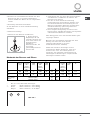
Burner and nozzle specifications
R
S
TEP 649 L
* At 15°C and 1013 mbar - dry gas
** Propane P.C.S. = 50.37 MJ/kg
*** Butane P.C.S. = 49.47 MJ/kg
Natural P.C.S. = 37.78 MJ/m
3
which is positioned
inside or next to the
valve pin, until the
flame is small but
steady.
3.Having adjusted the flame to the required low
setting, while the burner is alight, quickly change
the position of the knob from minimum to
maximum and vice versa several times, making
sure that the flame is not extinguished.
4. Some appliances have a safety device
(thermocouple) fitted. If the device fails to work
when the burners are set to the low flame setting,
increase this low flame setting using the adjusting
screw.
5. Once the adjustment has been made, replace the
seals on the by-passes using sealing wax or a
similar substance.
If the appliance is connected to liquid gas, the
adjustment screw must be fastened as tightly as
possible.
Once this procedure is complete, replace the old
rating sticker with one indicating the new type of gas
used. Stickers are available from any of our
Technical Assistance Centres.
If the gas pressure used is different (or varies
slightly) from the recommended pressure, a suitable
pressure regulator must be fitted to the inlet pipe (
in
order to comply with current national regulations
relating to regulators for channelled gas).
Table 1
Liquid gas
Natural gas
Heating
power
kW
(p.c.s.*)
Heating
power
kW
(p.c.s.*)
Flow rate*
g/h
Heating
power
kW
(p.c.s.*)
Burner Diameter
(mm)
Red.
By-Pass
1/100
(mm)
Nomin.
Nozzle
1/100
(mm)
*** ** Nomin.
Nozzle
1/100
(mm)
Flow
rate*
l/h
Rapid (R) 100 0,70 39 3,00 86 218 214 3,30 123 314
Semi-rapid
(S)
75 0,40 28 1,80 67 131 129 1,80 102 171
Supply
pressure
Nominal (mbar)
Minimal (mbar)
Maximised (mbar)
28-30
20
35
37
25
45
20
17
25

19
GB
PROGRAMME TIMER display shows the
programme selected (see Start-up and use).
PROGRAMME TIMER buttons control the
programmes for each cooking zone (see Start-up
and use).
COOKING ZONE PROGRAMMED indicator lights
show that a particular cooking zone has been
programmed (see Start-up and use).
ON/OFF button switches the appliance on and off.
CONTROL PANEL LOCK
button prevents
accidental changes to the hob settings (see Start-
up and use).
CONTROLS LOCKED indicator light shows the
control panel has been locked (see Start-up and
use).
BOOSTER button switches on the booster
function 3000 W of the cooking zone (see
Start-up and use).
COOKING ZONE SELECTOR indicator light
shows a particular cooking zone has been
selected and therefore various adjustments are
possible.
COOKING ZONE SELECTOR button is used to
select the desired cooking zone.
POWER indicator provides a visual display for the
current heat level.
INCREASE POWER button switches on the
hotplate and controls the power (see Start-up and
use).
REDUCE POWER button controls the power and
switches off the hotplate (see Start-up and use).
Control knobs for GAS BURNERS adjust the
flame setting.
GAS BURNER ignition enables a specific burner
to be lit automatically.
SAFETY DEVICE stops the gas flow if the flame
is accidentally extinguished.
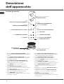
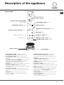
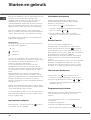
Control panel
Description of the appliance
SAFETY DEVICE
Ignition for GAS BURNERS
INCREASE POWER button REDUCE PO9ER button
PROGRAMME TIMER button
COOKING ZONE PROGRAMMED
indicator lights
PROGRAMME TIMER display
ON/OFF button
CONTROL PANEL LOCK button
CONTROL PANEL LOCK indicator
light
POWER indicator
BOOSTER button
COOKING ZONE SELECTED indicator
light
COOKING ZONE SELECTOR button
Control knobs for
GAS BURNERS
15
0
5.
b
o os
os
t e r

20
GB
The glue applied on the gaskets leaves traces of
grease on the glass. Before using the appliance, we
recommend you remove these with a special non-
abrasive cleaning product. During the first few hours
of use there may be a smell of rubber which will
disappear very quickly.
A few seconds after the hob is connected to the
electricity supply, a buzzer will sound. The hob may
now be switched on.
The position of the corresponding gas burner is
shown on every knob.
Gas burners
Each burner can be adjusted to one of the following
settings using the corresponding control knob:
Off
Maximum
Minimum
To light one of the burners, hold a lit match or lighter
near the burner and, at the same time, press down
and turn the corresponding knob anti-clockwise until
it reaches the maximum setting.
For models fitted with a safety device, the knob
should be held down for approximately 2-3 seconds,
until the automatic device keeping the flame alight
has heated up.
Some models are equipped with an ignition device
which is built into the knob. To light the selected
burner, press down and turn the corresponding
knob, then turn it an anti-clockwise direction until it
reaches the maximum setting. Keep it pressed
down until the burner has been lit successfully.
If the burner flame is accidentally extinguished,
shut off the control knob and wait for at least one
minute before attempting to light the burner again.
To switch off the burner, turn the knob in a clockwise
direction until it stops (when it reaches the
position).
Switching on the hob
To switch the hob on, press and hold the button
for approximately one second.
Switching on the cooking zones
The power of each cooking zone is controlled by a
device consisting of two buttons.
Press the
button to activate the hotplate, then
set the power to the desired level using the
and buttons.
To set the power to maximum, press and hold the
button briefly.
Booster function
The booster function for the rear cooking zones may
be used to shorten heating-up times. It is activated
by pressing the
b
b
oost erbbooostost erer
button. The letter P appears
on the power indicator display. This function boosts
the power of the corresponding zone to 3000 W.
It stops automatically after 4 minutes. While the
booster for one of the rear zones is active, the
maximum power of the front zones is limited to 600
W (e.g. if the rear left hotplate booster is activated,
the power of the front left hotplate decreases).
Switching off the cooking zones
Press the button; the power of the cooking
zone will progressively decrease until it is
switched off.
Alternatively, the
and buttons may be
pressed simultaneously. This immediately returns
the power setting to 0 and the cooking zone
switches off.
Programming the cooking duration
All the cooking zones may be programmed for a
length of time between 1 and 99 minutes.
1. Select the cooking zone using the corresponding
selector button.
2. Adjust the temperature.
3. Press the
programming button.
3. Set the cooking time using the
and
buttons.
Start-up and use

21
GB
4. Confirm by pressing the button.
The timer begins counting down immediately. A
buzzer sounds for approximately 1 minute and the
cooking zone switches off when the set programme
has finished.
Repeat the above procedure for each hotplate you
wish to programme.
Control panel lock
When the hob is switched on, it is possible to lock
the oven controls to prevent accidental changes
from being made to the settings (by children, during
cleaning, etc.). Press the
button to lock the
control panel: the indicator light above the button will
switch on. To use any of the controls (e.g. to stop
cooking), you must switch off this function. Press
the
button for a few moments; the indicator light
will switch off and the lock function will be removed.
Switching off the hob
Press the button to switch the appliance off.
If the control panel lock has been activated, the
controls will continue to be locked even after the hob
is switched on again. In order to switch the hob on
again, you must first remove the lock function.
Practical advice on using the appliance
Use cookware made from materials which are
compatible with the induction principle
(ferromagnetic material). We especially recommend
pans made from: cast iron, coated steel or special
stainless steel adapted for induction. Use a magnet
to test the compatibility of the cookware.
In addition, to achieve the best possible results
using your hob:
Use pans with a thick, flat base in order to fully
utilise the cooking zone.
Always use pans with a diameter which is large
enough to cover the hotplate fully, in order to use
all the available heat.
Make sure that the base of the cookware is
always clean and dry, in order to fully utilise and
extend the life of both the cooking zones and the
cookware.
Avoid using the same cookware which has been
used on gas burners: the heat concentration on
gas burners may distort the base of the pan,
causing it not to make full contact with the
cooking zone.
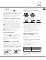
Practical advice on using the burners
To ensure the burners operate efficiently:
Use cookware which is suited to each burner (see
table) in order to prevent the flames from
extending beyond the base of the pans.
Always use cookware with a flat base and a
cover.
When the contents of the pan reach boiling point,
turn the knob to the minimum setting.
To identify the type of burner, please refer to the
diagrams contained in the paragraph entitled
Burner and nozzle specifications.
*
SUITABLE
UNSUITABLE
Cast iron
Enamelled steel
Special stainless steel
Copper,
Aluminium, Glass, Earthenware,
Ceramic, non magnetic Stainless steel
Burner ø Cookware Diameter (cm)
Fast (R) 24 - 26
Semi Fast (S) 16 - 20

22
GB
Safety devices
Pan sensor
Each cooking zone is equipped with a pan sensor
device. The hotplate only emits heat when a pan
with suitable measurements for the cooking zone is
placed on it. If the indicator light is flashing, it may
indicate:
An incompatible pan.
A pan with a diameter which is too small.
The pan has been removed from the hotplate.
Residual heat indicators
While the temperature of the cooking zone remains
above 60°C, even after the programme has finished,
the residual heat indicators placed near the relevant
cooking zone remain lit to prevent the risk of burns.
Overheating protection
If the electronic elements overheat, the hob switches
off automatically and appears on the display.
When a suitable temperature level has been
restored, this message disappears and the hob may
be used again.
Safety switch
The appliance has a safety switch which
automatically switches off the cooking zones when
they have been in operation for a certain amount of
time at a given power level. When the safety switch
has been triggered, the display shows 0.
Buzzer
This can also indicate several irregularities:
An object (a pan, cutlery, etc.) has been placed
on the control panel for more than 10 seconds.
Something has been spilt on the control panel.
A button has been pressed for too long. All of the
above situations may cause the buzzer to sound.
Remove the cause of the malfunction to stop the
buzzer. The control panel locks automatically in
the above situations. To unlock it press the [key
icon] button; the settings will have been
maintained. If the cause of the problem is not
removed, the buzzer will keep sounding and the
hob will switch off.

23
GB
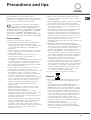
Precautions and tips
This appliance has been designed and
manufactured in compliance with international safety
standards. The following warnings are provided for
safety reasons and must be read carefully.
This appliance conforms to the following
European Economic Community directives:
2006/95/EEC dated 12/12/06 (Low Voltage) and
subsequent amendments - 89/336/EEC dated 03/05/
89 (Electromagnetic Compatibility) and subsequent
amendments - 93/68/EEC dated 22/07/93 and
subsequent amendments. 90/336/EEC dated 29/06/
90 (Gas) and subsequent amendments. 2002/96/EEC
General safety
This is a class 3 built-in appliance.
Gas appliances require regular air exchange in
order to maintain efficient operation. When
installing the hob, follow the instructions provided
in the paragraph relating to Positioning the
appliance.
These instructions are only valid for the countries
whose symbols appear in the manual and on the
serial number plate.
The appliance was designed for domestic use
inside the home and is not intended for
commercial or industrial use.
The appliance must not be installed outdoors, even
in covered areas. It is extremely dangerous to
leave the appliance exposed to rain and storms.
Do not touch the appliance with bare feet or with
wet or damp hands and feet.
Always make sure the knobs are in the l/
¡
position when the appliance is not in use.
The appliance must be used by adults only for the
preparation of food, in accordance with the
instructions provided in this booklet. Do not use
the hob as a worktop or chopping board.
The glass ceramic hob is resistant to mechanical
shocks, but it may crack (or even break) if struck
with a sharp object such as a utensil. If this
happens, disconnect the appliance from the
electricity mains immediately and contact a
Service Centre.
Make sure that power supply cables of other
electrical appliances do not come into contact
with the hot parts of the hob.
Remember that the cooking zones remain
relatively hot for at least thirty minutes after they
have been switched off. An indicator light
provides a warning when residual heat is present
(see Start-up and use).
Keep any object which could melt away from the
hob, for example plastic and aluminium objects,
or products with a high sugar content. Be
especially careful when using plastic film and
aluminium foil or packaging: if placed on surfaces
which are still hot, they may cause serious
damage to the hob.
Always make sure that pan handles are turned
towards the centre of the hob in order to avoid
accidental burns.
When unplugging the appliance, always pull the plug
from the mains socket;
do not pull on the cable.
Never perform any cleaning or maintenance work
without having disconnected the appliance from
the electricity mains.
The appliance should not be operated by people
(including children) with reduced physical,
sensory or mental capacities, by inexperienced
individuals or by anyone who is not familiar with
the product. These individuals should, at the very
least, be supervised by someone who assumes
responsibility for their safety or receive
preliminary instructions relating to the operation of
the appliance.
Warning for people who have been fitted with
pacemakers or other active internal medical devices:
The hob conforms to all current legislation relating
to electromagnetic interference. This product
therefore fully conforms with all legal requirements
(directive 89/336/EEC). It was designed not to
create interference with other electrical equipment
used nearby, provided that the other equipment
also conforms fully with all the above legislation.
The induction hob generates short range
electromagnetic fields.To avoid all risks of
interference between the hob and the pacemaker,
the pacemaker should be made in accordance
with all current legislation. We can only guarantee
the conformity of our product in this matter.
For
further information relating to conformity or any
incompatibility problems, please contact your
G.P. or the pacemaker manufacturer.
Do not let children play with the appliance.
Disposal
When disposing of packaging material: observe
local legislation so that the packaging may be
reused.
The European Directive 2002/96/EC relating to
Waste Electrical and Electronic Equipment
(WEEE) states that household appliances should
not be disposed of using the normal solid urban
waste cycle. Exhausted appliances should be
collected separately in order to optimise the cost
of re-using and recycling the materials inside the
machine, while preventing potential damage to
the atmosphere and to public health. The
crossed-out dustbin is marked on all products to
remind the owner of their obligations regarding
separated waste collection.
For further information relating to the correct
disposal of exhausted household appliances,
owners may contact the public service provided
or their local dealer.

24
GB
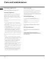
Care and maintenance
Switching the appliance off
Disconnect your appliance from the electricity
supply before carrying out any work on it.
Cleaning the appliance
Do not use abrasive or corrosive detergents (for
example, products in spray cans for cleaning
barbecues and ovens), stain removers, anti-rust
products, powder detergents or sponges with
abrasive surfaces: these may scratch the surface
beyond repair.
Never use steam cleaners or pressure cleaners on
the appliance.
It is usually sufficient simply to wash the hob
using a damp sponge and dry it with absorbent
kitchen towel.
If the hob is particularly dirty, rub it with a special
glass ceramic cleaning product, then rinse well
and dry thoroughly.
To remove more stubborn dirt, use the scraper
provided. Remove spills as soon as possible,
without waiting for the appliance to cool, to
prevent residues from forming crusty deposits.
You can achieve excellent results by using a rust-
proof steel wire sponge - specifically designed for
glass ceramic surfaces - soaked in soapy water.
The scraper provided is sharp: be careful when
using it.
If plastic or sugary substances are accidentally
melted on the hob, remove them immediately with
the scraper, while the surface is still hot.
Once it is clean, the hob may be treated with a
special protective maintenance product: the
invisible film left by this product protects the
surface from drips during cooking. This
maintenance task should be carried out while the
appliance is warm (not hot) or cold.
Always remember to rinse the appliance well with
clean water and dry it thoroughly: residues can
become encrusted during subsequent cooking
processes.
For hobs which light automatically, the terminal
part of the electronic instant lighting devices
should be cleaned frequently and the gas outlet
holes should be checked for blockages.
Stainless steel frame
(only for models with outer frame)
Stainless steel can be marked by hard water which
has been left on the surface for a long time, or by
cleaning products containing phosphorus. After
cleaning, it is advisable to rinse the surface well and
dry it thoroughly. If water is spilt on the surface, dry
it quickly and thoroughly.
Disassembling the hob
If it is necessary to disassemble the hob:
1. Loosen the screws fixing the alignment springs on
each side.
2. Loosen the screws holding the fixing hooks in
each corner.
3. Take the hob out of its installation cavity.
Do not attempt to repair the appliance yourself.
If the appliance breaks down, contact a Service
Centre.
Gas valve maintenance
Over time, the valves may become jammed or
difficult to turn. If this occurs, the valve must be
replaced.
This procedure must be performed by a
qualified technician who has been authorised by
the manufacturer.

25
GB
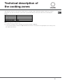
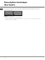
Technical description of
the cooking zones
The induction system is the quickest existing way of cooking. Unlike traditional hotplates where the cooking
zone heats up, with the induction system heat is generated directly inside pans which have ferromagnetic
bases.
Key:
I = single induction cooking zone
B = booster: the power of the cooking zone may be boosted to 3000 W
* = the maximum power is limited to 600 W while the booster is activated for the appropriate rear cooking zone
(see Start-up and use).
HOBS
TEP 649 L
Cooking zone Power
Front right I 1200 W – 600 W if*
Front left I 1800 W – B 3000 W
Maximum total power 3600

26
GB
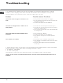
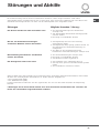
It may happen that the appliance does not function properly or at all. Before calling the service centre for
assistance, check if anything can be done. First make sure that there are no interruptions in the gas and
electrical supplies, and, in particular, that the mains gas supply valves are open.
Troubleshooting
Possible causes / Solutions:
The gas holes on the burner are clogged.
All the movable parts that make up the burner are
assembled correctly.
There are draughts near the appliance.
The knob has not been pressed all the way in.
The knob has not been pressed in long enough to
activate the safety device.
The gas holes are blocked in the area aligned with
the safety device.
The gas holes are blocked.
There are draughts near the appliance.
The minimum setting has not been adjusted
properly.
The bottom of the cookware is perfectly flat.
The cookware is positioned correctly at the centre
of the burner.
The pan support grids have been positioned
incorrectly.
Problem
The burner does not light or the flame is not
even.
The flame is extinguished in models with a
safety device.
T
he burner does not remain lit when set to
minimum.
The cookware is unstable.
If, despite all these checks, the hob does not function properly and the problem persists, contact your nearest
Technical Assistance Centre. Please have the following information to hand:
The appliance model (Mod.).
The serial number (S/N).
This information can be found on the data plate located on the appliance and/or on the packaging.
Nev
er use the services of unauthorised technicians and never accept replacement parts which are not
authentic.
Page is loading ...
Page is loading ...
Page is loading ...
Page is loading ...
Page is loading ...
Page is loading ...
Page is loading ...
Page is loading ...
Page is loading ...
Page is loading ...
Page is loading ...
Page is loading ...
Page is loading ...
Page is loading ...
Page is loading ...
Page is loading ...
Page is loading ...
Page is loading ...
Page is loading ...
Page is loading ...
Page is loading ...
Page is loading ...
Page is loading ...
Page is loading ...
Page is loading ...
Page is loading ...
Page is loading ...
Page is loading ...
Page is loading ...
Page is loading ...
Page is loading ...
Page is loading ...
Page is loading ...
Page is loading ...
Page is loading ...
Page is loading ...
Page is loading ...
Page is loading ...
Page is loading ...
Page is loading ...
Page is loading ...
Page is loading ...
-
 1
1
-
 2
2
-
 3
3
-
 4
4
-
 5
5
-
 6
6
-
 7
7
-
 8
8
-
 9
9
-
 10
10
-
 11
11
-
 12
12
-
 13
13
-
 14
14
-
 15
15
-
 16
16
-
 17
17
-
 18
18
-
 19
19
-
 20
20
-
 21
21
-
 22
22
-
 23
23
-
 24
24
-
 25
25
-
 26
26
-
 27
27
-
 28
28
-
 29
29
-
 30
30
-
 31
31
-
 32
32
-
 33
33
-
 34
34
-
 35
35
-
 36
36
-
 37
37
-
 38
38
-
 39
39
-
 40
40
-
 41
41
-
 42
42
-
 43
43
-
 44
44
-
 45
45
-
 46
46
-
 47
47
-
 48
48
-
 49
49
-
 50
50
-
 51
51
-
 52
52
-
 53
53
-
 54
54
-
 55
55
-
 56
56
-
 57
57
-
 58
58
-
 59
59
-
 60
60
-
 61
61
-
 62
62
-
 63
63
-
 64
64
-
 65
65
-
 66
66
-
 67
67
-
 68
68


Ask a question and I''ll find the answer in the document
Finding information in a document is now easier with AI
in other languages
- italiano: Whirlpool TEP 649 L Guida utente
- français: Whirlpool TEP 649 L Mode d'emploi
Related papers
-
Whirlpool TM 7320 (NR) User guide
-
-
Whirlpool TIL 641 Owner's manual
-
-
-
Whirlpool TG 751 (IX) GH (EU) Owner's manual
-
Whirlpool PH 741 RQO GH/HA Operating instructions
-
-
-
Whirlpool TI 6312 NR User guide
Other documents
-
Indesit TEM 748.1 L User guide
-
-
Scholtes TI 6533 (NR) Owner's manual
-
Indesit PH 730 RT (IX) User guide
-
-
-
-
-
HOTPOINT/ARISTON PKL 752 T/EX/HA User guide
-