Craftsman 358.796270 Owner's manual
- Category
- Grass trimmers
- Type
- Owner's manual
This manual is also suitable for

Operator's Manual
®
CRAFTSMAN
24cc/1.46 cu.in. 2-Cycle
17 Inch Cutting Path
GASOLINE WEEDWAOKER ®
Model No.
358.796270
WARNING:
Read and follow all Safety Rules and Operating
Instructions before first use of this product.
t_ For answers to your questions about this product:
Call 7 am-7 pm, Mon-Sat; Sun, 10 am-7 pm
• 1-800-235-5878
Sears, Roebuck and Co., Hoffman Estates, IL 60179 USA
530088523 3/t 5/00
/
g
0
/
0
g

Warranty Statement 2 Storage 11
Safety Rules 2 Troubleshooting Chart 12
Assembly 4 Emissions Statement 12
Operation 5 Repair Parts List 14
Maintenance 8 Spanish 17
Service & Adjustments 9 Parts and Ordering Back Cover
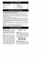
FULL ONE YEAR WARRANTY ON CRAFTSMAN GAS POWERED
WEEDWACKER ® LINE TRIMMER
For one year from the date of purchase, when this Craftsman Gas Powered
WeedwackeKR: Line Trimmer is maintained, lubricated, and tuned up according to
the operating and maintenance instructions in the Operator's Manual, Sears will
repair, free of charge, any defect in materials or workmanship.
This warranty excludes nylon line, spark plug, and air filter, which are expendable
parts and become worn during normal use.
If this WeedwackerrR; Line Trimmer is used for commercial purposes, this warran-
ty applies for only 90 days from the date of purchase. If this WeedwackeK_ Line
Trimmer is used for rental purposes, this warranty applies for only 30 days from
the date of purchase. This warranty applies only while this product is in use in the
United States.
WARRANTY SERVICE IS AVAILABLE BY RETURNING THE WEEDWACKERrR; LINE
TRIMMER TO THE NEAREST SEARS SERVICE CENTER IN THE UNITED STATES.
This warranty gives you specific legal rights, and you may also have other rights
which vary from state to state.
Sears, Roebuck and Co., D/817 WA Hoffman Estates, IL 60179
_WARNING: When using garden-
ing appliances, basic safety precau-
tions must always be followed to re-
duce the risk of fire and serious injury.
Read and follow all instructions.
This power unit can be dangerous!
Operator is responsible for following
instructions and warnings on unit and
in manual. Read entire Operator's
Manual before using unit! Be thor-
oughly familiar with the controls and
the proper use of the unit. Restrict the
use of this unit to persons who have
read, understand, and will follow the
instructions and warnings on the unit
and in the manual. Never allow chil-
dren to operate this unit.
_Y INFORMATION
ON THE UNIT
A
dl_ DANGER: Never use blades or
flailing devices. This unit is designed
for line trimmer use only. Use of any
other accessories or attachments will
increase the risk of injury.
@0©
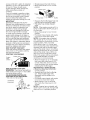
_,WARNING: Trimmer line throws
objects violently. You and others can
be blinded/injured. Wear eye and leg
protection. Keep body parts clear of
rotating line. Keep children, bystand-
ers, and animals 50 feet (15 m) away.
If approached, stop unit immediately.
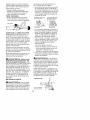
Eye Protection
\

• If situations occur which are not cov-
ered in this manual, use care and
good judgement. If you need assis-
tance, contact your Sears Service
Center or call 1-800-235-5878.
OPERATOR SAFETY
• Always wear safety eye protection.
• Always wear long pants, long
sleeves, boots, and gloves. Wearing
safety leg guards is recommended.
Do not go barefoot or wear sandals.
Stay clear of spinning line.
• Secure hair above shoulder length.
Secure or remove loose clothing or
clothing with loosely hanging ties,
straps, tassels, etc. They can be
caught in moving parts.
• Do not operate when you are tired,
ill, or under the influence of alcohol,
drugs, or medication.
• Wear hearing protection if you use
unit for more than 1-1/2 hours per
day.
• Never start or run inside a closed
room or building. Breathing exhaust
fumes can kill.
• Keep handles free of oil and fuel.
UNIT / MAINTENANCE SAFETY
• Disconnect the spark plug before
performing maintenance except car-
buretor adjustments.
• Look for and replace damaged or
loose parts before each use. Look
for and repair fuel leaks before use.
Keep in good working condition.
• Replace trimmer head parts that are
chipped, cracked, broken, or dam-
aged in any other way before using
the unit.
• Make sure unit is assembled cor-
rectly as shown in this manual.
• Make carburetor adjustments with
lower end supported to prevent line
from contacting any object.
• Keep others away when making car-
buretor adjustments.
• Use only recommended Craftsman
accessories and replacement parts.
FUEL SAFETY
• Mix and pour fuel outdoors.
• Keep away from sparks or flames.
• Use a container approved for fuel.
• Do not smoke or allow smoking near
fuel or the unit.
• Wipe up all fuel spills.
• Move at least 10 feet (3 meters)
away from fueling site before start-
ing engine.
• Stop engine and allow to cool before
removing fuel cap.
CUTTING SAFETY
• Use only for trimming, mowing, edg-
ing, and sweeping. Do not use for
pruning or hedge trimming.
• Inspect the area before each use.
Remove objects (rocks, broken
glass, nails, wire, etc.) which can be
thrown by or become entangled in
line. Hard objects can damage the
trimmer head and be thrown causing
serious injury.
• Keep firm footing and balance. Do
not overreach.
• Keep all parts of your body away
from muffler and spinning line. Keep
engine below waist level. A hot muf-
fler can cause serious burns.
• Cutting on left side of the shield will
throw debris away from the operator.
TRANSPORTING AND STORAGE
• Allow engine to cool; secure unit be-
fore storing or transporting in ve-
hicle.
• Empty the fuel tank before storing or
transporting the unit. Use up fuel left
in the carburetor by starting the en-
gine and letting it run until it stops.
• Store unit and fuel in area where
fuel vapors cannot reach sparks or
open flames from water heaters,
electric motors or switches, fur-
Races, etc.
• Store unit so line limiter cannot acci-
dentally cause injury. The unit can
be hung by the tube.
• Store unit out of reach of children.
• If situations occur which are not cov-
ered in this manual, use care and
good judgment. If you need assis-
tance, call 1-800-235-5878.
SPECIAL NOTICE: This unit is not
equipped with a temperature limiting
muffler and spark arresting screen
which meets the requirements of Cali-
fornia Codes 4442 and 4443. All U.S.
forest land and the states of California,
Idaho, Maine, Minnesota, New Jersey,
Oregon, and Washington require by
law that many internal combustion en-
gines be equipped with a spark arres-

tarscreen.Ifyouoperateinalocale
wheresuchregulationsexist,youare
legallyresponsibleforinstallingand
maintainingtheoperatingconditionof
theseparts.Failuretodosoisaviola-
tionofthelaw.ContactyourSears
ServiceCenterforthecorrectparts.
SPECIALNOTICE:Exposureto
vibrationsthroughprolongeduseof
gasolinepoweredhandtoolscould
causebloodvesselornervedamage
inthefingers,hands,andjointsof
peoplepronetocirculationdisorders
orabnormalswellings.Prolongeduse
incoldweatherhasbeenlinkedto
bloodvesseldamageinotherwise
healthypeople.Ifsymptomsoccur
suchasnumbness,pain,lossof
strength,changeinskincolorortex-
ture,orlossoffeelinginthefingers,
hands,orjoints,discontinuetheuseof
thistoolandseekmedicalattention.
Ananti-vibrationsystemdoesnot
guaranteetheavoidanceofthese
problems.Userswhooperatepower
toolsonacontinualandregularbasis
mustmonitorcloselytheirphysical
conditionandtheconditionofthistool.
CARTONCONTENTS
Checkcartoncontentsagainstthefol-
lowinglist.
Model358.796270
• Trimmer
• Shieldwithwingnut
• AssistHandlewithboltandknob
• Containerofoil
• Replacementspool
Examinepartsfordamage.Donot
usedamagedparts.
NOTE:Ifyouneedassistanceorfind
partsmissingordamaged,call
1-800-235-5878.
Itisnormalforthefuelfiltertorattlein
theempty fuel tank.
Finding fuel or oil residue on muffler is
normal due to carburetor adjustments
and testing done by the manufacturer.
ASSEMBLY
,_WARNING: If received as-
sembled, repeat all steps to ensure
your unit is properly assembled and all
fasteners are secure.
Be sure to assemble the handle to the
unit before you assemble the shield.
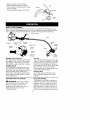
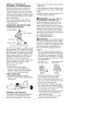
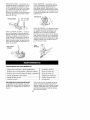
ATTACHING THE HANDLE
(some units are already assembled)
Groove /
• Assemble handle to the unit as
shown; make sure bottom of handle
is seated in the groove in the trigger
housing.
NOTE: Knob must be assembled on
the right hand side of the unit as
shown in the illustration.
• Make sure the bolt is seated into the
hex-shaped hole in the handle.
• Pivot handle to a comfortable posi-
tion.
• Tighten handle securely.
ATTACHING SHIELD
_ WARNING: The shield must be
properly installed. The shield provides
partial protection from the risk of thrown
objects to the operator and others and
is equipped with a line limiter which cuts
excess line to the proper length. The
line limiter (on underside of shield) is
sharp and can cut you. For proper
orientation, see illustration in OPERA-
TION section.

• Removewingnutfromshield.
• Insertbracketintoslotasshown.
• Pivotshielduntilboltpassesthrough
holeinbracket.
• Securelytightenwingnutontobolt.
Slot
Shield "_\/
_ _._F--_"__,)")Bracket
" _) Wing
_ nut
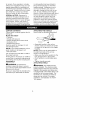
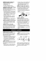
KNOW YOUR TRIMMER
READ THIS OPERATOR'S MANUAL AND SAFETY RULES BEFORE OPERATING YOUR
UNIT. Compare the illustrations with your unit to familiarize yourself with the location
of the various controls and adjustments. Save this manual for future reference.
b_ Assist Handle
Tube
Muffler
Engine Stop \ Throttle Trimmer
Switch Trigger Edge
Spark Plug Guide
Starter
Rope _ Choke
Lever Shield
Primer
Bulb
Fuel Mix
Fill Cap
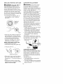
ENGINE STOP SWITCH
Tile engine STOP switch is used to stop
the engine. Push and hold the engine
stop switch in the STOP or OFF posi-
tion until the engine has fully stopped.
PRIMER BULB
The PRIMER BULB removes air from
the carburetor and fuel lines and fills
them with fuel. This allows you to start
the engine with fewer pulls on the
starter rope. Activate the primer bulb
by pressing it and allowing it to return
to its original form.
Line
Limiter
Blade
CHOKE
The CHOKE helps to supply fuel to the
engine to aid in cold starting. Activate
the choke by moving the choke lever
to the FULL CHOKE position. After en-
gine attempts to start, move the choke
lever to the HALF CHOKE position.
Once engine starts, move choke lever
to the OFF CHOKE position.
EDGE GUIDE
The EDGE GUIDE protects the unit
from contacting the ground during
edging.
BEFORE STARTING ENGINE
_WARNING: Be sure to read the
fuel information in the safety rules
before you begin. Ifyou do not
understand the safety rules, do not
attempt to fuel your unit. Call
1-800-235-5878.
FUELING ENGINE
This engine is certified to operate on
unleaded gasoline. Before operation,
gasoline must be mixed with a good
quality 2-cycle air-cooled engine oil.
We recommend Craftsman brand oil.
Mix gasoline and oil at a ratio of 40:1
(A 40:1 ratio is obtained by mixing 3.2
5

ouncesofoilwith1gallonofunleaded
gasoline).DONOTUSEautomotiveoil
orboatoil.Theseoilswillcause
enginedamage.Whenmixingfuel,
followinstructionsprintedon
container.
Onceoilisaddedtogasoline,shake
containermomentarilytoassurethat
thefuelisthoroughlymixed.Always
readandfollowthesafetyrules
relatingtofuelbeforefuelingyourunit.
IMPORTANT
Experienceindicatesthatalcohol
blendedfuels(calledgasoholorusing
ethanolormethanol)canattractmois-
turewhichleadstoseparationand
formationofacidsduringstorage.
Acidicgascandamagethefuelsys-
temofanenginewhileinstorage.
Toavoidengineproblems,emptyfuel
systembeforestoragefor30daysor
longer.Draingastank,startengineand
letitrununtilfuellinesandcarburetor
areempty.Usefreshfuelnextseason.
Neveruseengineorcarburetorcleaner
productsinthefueltankorpermanent
damagemayoccur.SeetheSTORAGE
sectionforadditionalinformation.
HOW TO STOP YOUR UNIT
Push and hold tile engine stop switch
in the STOP or OFF position until the
unit has fully stopped.
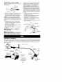
STARTING YOUR ENGINE
Choke Lever
Engine
Stop
Switch _
p,
HOW TO START YOUR UNIT
WARNING: The trimmer head will turn
while starting the engine. A hot muffler
can cause serious burns.
COLD ENGINE STARTING OR
STARTING AFTER REFUELING
• Set unit on a flat surface.
STARTING _
POSITION
• Slowly press primer bulb 6 times.
• Move choke lever to FULL CHOKE-
position.
Choke Lever
Primer Bulb \i_J_''_'l_// Muffler
• Squeeze the throttle trigger fully and
hold through all remaining steps.
• Pull starter rope handle sharply 6
times.
NOTE: If the engine sounds as if it is
trying to start before the 6th pull, go to
the next step.
• Move choke lever to HALF CHOKE
position.
• Pull starter rope sharply until engine
runs, but no more than 6 pulls.
NOTE: If the engine has not started
after 6 pulls (at HALF CHOKE), check
to make sure the choke lever is in the
proper position. Then, move the
choke lever to the FULL CHOKE posi-
tion and press the primer bulb 6 times;
squeeze and hold the throttle trigger
and pull the starter rope 2 more times.
Move the choke lever to HALF CHOKE
and pull the starter rope until the en-
gine runs, but no more than 6 more
pulls. If the engine still has not started,
it is probably flooded. Proceed to
STARTING A FLOODED ENGINE.
• Allow the engine to run 10 seconds,
then move the choke lever to OFF
CHOKE. Allow the unit to run for 30
more seconds at OFF CHOKE before
releasing the throttle trigger.
RESTARTING A WARM ENGINE
• Move the choke lever to the HALF
CHOKE position.
• Squeeze and hold the throttle trig-
ger. Keep throttle trigger fully
squeezed until the engine runs
smoothly.
• Pull starter rope sharply until engine
runs, but no more than 5 pulls.
• Allow engine to run 15 seconds,
then move the choke lever to OFF
CHOKE.
NOTE: If engine has not started, pull
starter rope 5 more pulls. If engine still
does not run, it is probably flooded=
6

DIFFICULT STARTING OR
STARTING A FLOODED ENGINE
Flooded engines can be started by
placing the choke lever in the OFF
CHOKE position; then, pull the rope to
clear the engine of excess fuel. This
could require pulling the starter handle
many times depending on how badly
the unit is flooded.
If the unit still doesn't start, refer to
TROUBLESHO©TING CHART or call
1-800-235-5878.
OPERATING INSTRUCTIONS
OPERATING POSITION
ALWAYS WEAR:
Eye Protection
Lonc
Heav
Cut from your right to your left.
Do not run the engine at a higher speed
than necessary. The cutting line will cut
efficiently when the engine is run at less
than full throttle. At lower speeds, there
is less engine noise and vibration. The
cutting line will last longer and will be
less likely to "weld" onto the spool.
Always release the throttle trigger and
allow the engine to return to idle
speed when not cutting.
To stop engine:
• Release the throttle trigger.
• Push and hold the engine stop
switch in the STOP or OFF position
until the unit has fully stopped.
TWIST AND EDGE
• Pull the tab toward ttle engine.
• Twist the tube to the edging position;
release tab.
TRIMMER LINE ADVANCE
The cutting head advances line auto-
matically. Do not tap head on the
ground to advance line. This may
break parts and cause cutting head to
malfunction.
Upon unit start up, the line will advance
automatically to the correct cutting path
length.
Always keep the shield in place when
the tool is being operated.
411WARNING: Use only .080" (2
mm) diameter round line. Other
sizes and shapes of line will not ad-
vance properly and will result in im-
proper cutting head function or can
cause serious injury. Do not use other
materials such as wire, string, rope,
etc. Wire can break off during cutting
and become a dangerous missile that
can cause serious injury.
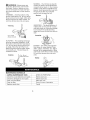
CUTTING METHODS
_kWARNING: Use minimum speed
and do not crowd the line when cutting
around hard objects (rock, gravel, fence
posts, etc.), which can damage the trim-
mer head, become entangled in the
line, or be thrown causing a serious
hazard.
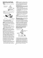
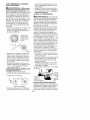
• The tip of the line does the cutting.
You will achieve the best performance
and minimum line wear by not crowd-
ing the line into cutting area. The right
and wrong ways are shown in the fol-
lowing illustration.
Tip of the Line Line Crowded Into
Does The Cutting Work Area
Night Wrong
• The line will easily remove grass
and weeds from around walls,
fences, trees and flower beds, but it
also can cut the tender bark of trees
or shrubs and scar fences.
• For trimming or scalping, use less
than full throttle to increase line life
and decrease head wear, especially:
• During light duty cutting.
• Near objects around which the line
can wrap such as small posts,
trees or fence wire.
• For mowing or sweeping, use full
throttle for a good clean job.
7

A
41 WARNING: Always wear eye
protection. Never lean over the trim-
mer head, Rocks or debris can rico-
chet or be thrown into eyes and face
and cause blindness or other serious
injury.
TRIMMING - Hold the bottom of the
trimmer head about 3 in. (8 cm) above
the ground and at an angle. Allow only
the tip of the line to make contact. Do
not force trimmer line into work area.
Trimming __ 1t
AboveGrJon
SCALPING - The scalping technique
removes unwanted vegetation. Hold
the bottom of the trimmer head about
3 in. (8 cm) above the ground and at
an angle. Allow the tip of the line to
strike the ground around trees, posts,
monuments, etc. This technique in-
creases line wear.
Scalping
MOWING - Your trimmer is ideal for
mowing in places conventional lawn
mowers cannot reach. In the mowing
position, keep the line parallel to the
ground. Avoid pressing the head into
the ground as this can scalp the
ground and damage the tool.
cow,no))
SWEEPING - The fanning action of
rotating line can be used for a quick
and easy clean up. Keep line parallel
to and above the surfaces being
swept and move the tool from side to
side.
Sweeping_ .....
EDGING - The Twist and Edge fea-
ture allows for easy edging of side-
walks, patios, driveways, etc. Adjust
trimmer to the edging position. Allow
only the tip of the line to make contact.
Do not force trimmer line into work
3 in. (8 ore) area.
Above Ground
Edging _,_
_,_;_,:_;_7..-_ _..
MAINTENANCE SCHEDULE
CARE & MAINTENANCE TASK WHEN TO PERFORM
Check for Loose fasteners and parts Before each use
Check for damaged or worn parts Before each use
Clean unit and labels After each use
Clean air filter Every 5 hours of operation
Replace spark plug Yearly

GENERAL RECOMMEN DATIONS
The warranty on this unit does not
cover items that have been subjected
to operator abuse or negligence. To
receive full value from the warranty,
the operator must maintain unit as
instructed in this manual. Various ad-
justments will need to be made peri-
odically to properly maintain your unit.
CHECK FOR LOOSE
FASTENERS AND PARTS
• Spark Plug Boot
• Air Filter
• Housing Screws
• Assist Handle Screws
• Shield Screw
CHECK FOR DAMAGED OR
WORN PARTS
Refer replacement of damaged/worn
parts to your Sears Service Center.
• Engine STOP Switch - Ensure
switch functions properly by press-
ing and holding the switch in the
STOP position. Make sure engine
stops; then restart engine and con-
tinue.
• Fuel Tank - Do not use unit if fuel
tank shows signs of damage or leaks.
• Shield - Discontinue use of unit if
debris shield is damaged.
CLEAN UNIT & LABELS
• Clean the unit using a damp cloth
with a mild detergent.
• Wipe off unit with a clean dry cloth.
CLEAN AIR FILTER
A dirty air filter decreases engine per-
formance and increases fuel con-
sumption and harmful emissions. Al-
ways clean after every 5 hours of
operation.
• Clean the cover and the area
around it to keep dirt and debris
from falling into the carburetor
chamber when the cover is
removed.
• Remove parts as illustrated.
NOTE: Do not clean filter in gasoline
or other flammable solvent to avoid
creating a fire hazard or producing
harmful evaporative emissions.
• Wash the filter in soap and water.
• Allow filter to dry.
• Replace parts.
f_. ,_Filter
_/_ -4_,_ Screws
REPLACE SPARK PLUG
Replace the spark plug each year to
ensure the engine starts easier and
runs better. Set spark plug gap at
0.025 in. Ignition timing is fixed and
nonadjustable.
• Twist, then pull off spark plug boot.
• Remove spark plug from cylinder
and discard.
• Replace with Champion RCJ-8Y
spark plug and tighten with a 3/4 in.
socket wrench (10-12 ft.-Ibs).
• Reinstall the spark plug boot.
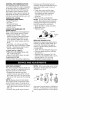
LINE REPLACEMENT
Pre-wound spools offer the most con-
venient method for replacing line and
ensuring optimum performance.
• Replacement spools are color-
coded to ensure use of the correct
spool with your unit. Be sure to use
the same color spool as the existing
spool.
NOTE: Always clear dirt and debris
from cutting head components when
performing any type of maintenance.
• Hold spool and unscrew cap by turn-
ing in the direction shown on top of
the cap.
• Remove line guide ring and spool.
NOTE: When removing and/or instal-
ling spool, ensure dust cup remains
installed over shaft.
Dust Spool Lin_e Cap
Shaft ciP ,.,_'q_,_, r,ng jf
Use a pre-wound spool or refill spool
with line. If using a pre-wound spool,
remove tape strip from line and spool.
9

REFILLING THE SPOOL WITH LINE
_WARNING: Use only .080" (2
mm) diameter round line. Other
sizes and shapes of line will not ad-
vance properly and will result in im-
proper cutting head function or can
cause serious injury. Do not use other
materials such as wire, string, rope,
etc. Wire can break off during cutting
and become a dangerous missile that
can cause serious injury.
• Cut a length of 30 feet of .080" (2
ram) diameter round Craftsman
brand line=
Spool
• Insert one end of line into center cav-
ity of empty spool. Ensure line will
feed into spool in the direction shown
on the spool (counterclockwise).
• Continue feeding line into spool,
leaving 4 - 6 inches (10 - 15 cm)
unwound from center of spool.
INSTALLING SPOOL WITH LINE
• Install replacement spool.
• Thread line through line guide ring.
CARBURETOR ADJUSTMENT
_L WARNING: The trimmer head
will be spinning during most of this
procedure. Wear your protective
equipment and observe all safety pre-
cautions. After making mixture adjust-
ments, recheck idle speed.
Carburetor adjustment is critical and if
done improperly can permanently
damage the engine as well as the car-
buretor. If you require further assis-
tance or are unsure about performing
this procedure, call 1-800-235-5878.
Old fuel, a dirty air filter, a dirty fuel fil-
ter, or flooding may give the impres-
sion of an improperly adjusted carbu-
retor. Check these conditions before
adjusting the carburetor.
The carburetor has been carefully set
at the factory. Adjustments may be
necessary if you notice any of the fol-
lowing conditions:
• Engine will not idle, See IDLE SPEED
under adjusting procedure.
• Engine dies or hesitates instead of
accelerating. See ACCELERATION
CHECK under adjusting procedure.
• Loss of cutting power. See MIXTURE
ADJUSTMENT under adjusting
procedure.
There are two adjustment screws on
the carburetor. They are located in the
area just above the primer bulb.
Mixture Screw (with
Limiter Cap)
Idle
3peed
Screw
Linethrough guide ring
ff
Replacement Spool
• Rest guide ring on spool and place
line in slot. Allow line to extend 4 -
6 inches (10 - 15 cm) from center of
spool.
• Ensure line remains in slot while
screwing cap on to the shaft. Only
tighten cap hand tightt
Air Filter
Cover
CARBURETOR PRESETS
When making carburetor preset adjust-
ments, do not force plastic limiter caps
beyond stops or damage will occur.
If carburetor presets are not needed,
proceed to ADJUSTING PROCEDURE,
IDLE SPEED.
To adiust presets:
• Turn mixture screw counterclock-
wise until it stops.
• Turn the idle speed screw clockwise
until it stops. Now turn counterclock-
wise 4-1/2 turns.
10

• Startengine,cutgrassfor3
minutes,andproceedtothe
adjustmentsection.Ifenginedoes
notstart,
refertoTROUBLESHOOTINGCHART
orcall1-800-235-5878.
• Ifengineperformanceisacceptable
atthepresetpositions,nofurther
adjustmentisnecessary.
ADJUSTING PROCEDURE
Idle Speed
Allow engine to idle. Adjust speed until
engine runs without stalling.
• Turn clockwise to increase engine
speed if engine stalls or dies.
• Turn counterclockwise to decrease
speed.
No further adjustments are necessary
if performance is satisfactory.
Mixture Adjustment "H"
DO NOT operate engine at full throttle
for prolonged periods while making
adjustments. Damage to the engine
can occur. Ensure line is fully ex-
tended.
Based on performance while cutting,
turn the mixture adjustment in
1/16-turn increments as follows:
• Clockwise until the engine has good
power while cutting with no hesita-
tion.
Do not adjust by sound or speed,
but judge by how well the engine
performs while cutting.
• Counterclockwise if the engine has
speed but dies or lacks power while
cutting.
After completing adjustments, check
for acceleration. Reset if necessary.
Acceleration Check
If engine dies or hesitates instead of
accelerating, turn mixture adjustment
counterclockwise until you have
smooth acceleration. Recheck and
adjust as necessary for acceptable
performance.
Prepare unit for storage at end of sea-
son or if it will not be used for 30 days
or more.
_WARNING:
• Allow engine to cool, and secure the
unit before storing or transporting.
• Store unit and fuel in a well venti-
lated area where fuel vapors cannot
reach sparks or open flames from
water heaters, electric motors or
switches, furnaces, etc.
• Store unit with all guards in place.
Position unit so that any sharp ob-
ject cannot accidentally cause injury.
• Store unit and fuel well out of the
reach of children.
EXTERNAL SURFACES
If your unit is to be stored for a period
of time, clean it thoroughly before stor-
age. Store in a clean dry area.
• Lightly oil external metal surfaces.
FUEL SYSTEM
Under FUELING ENGINE in the OPERA-
TION section of this manual, see mes-
sage labeled IMPORTANT regarding
the use of gasohol in your engine.
Fuel stabilizer is an acceptable alter-
native in minimizing the formation of
fuel gum deposits during storage. Add
stabilizer to the gasoline in the fuel
tank or fuel storage container. Follow
the mix instructions found on stabilizer
container. Run engine at least 5 min-
utes after adding stabilizer.
Craftsman 40:1,2-cycle engine oil (air
cooled) is already blended with fuel
stabilizer. If you do not use this Sears
oil, you can add a fuel stabilizer to
your fuel tank.
ENGINE
• Remove spark plug and pour 1 tea-
spoon of 40:1,2-cycle engine oil (air
cooled) through the spark plug
opening. Slowly pull the starter rope
8 to 10 times to distribute oil.
• Replace spark plug with new one of
recommended type and heat range.
• Clean air filter.
• Check entire unit for loose screws,
nuts, and bolts. Replace any dam-
aged, broken, or worn parts.
• At the beginning of the next season,
use only fresh fuel having the proper
gasoline to oil ratio.
OTHER
• Do not store gasoline from one sea-
son to another.
• Replace gasoline can if it starts to
rust.
11

TROUBLESHOOTING CHART
TROUBLE CAUSE
Engine will not • Engine flooded.
start. • Fuel tank empty.
• Spark plug not firing.
• Fuel not reaching
carburetor.
• Compression low.
Engine will not • Idle speed set too low=
idle properly.
Engine will not
accelerate,
lacks power,
or dies under
a load.
Engine smokes
excessively.
Engine runs hot.
• Idle speed set too high.
• Carburetor requires
adjustment.
• Crankshaft seals worn.
• Compression low.
• Air filter dirty.
• Spark plug fouled.
• Carburetor requires
adjustment.
• Carbon build up.
• Compression low.
• Choke partially on.
• Fuel mixture incorrect.
• Air filter dirty.
• Carburetor requires
adjustment.
• Fuel mixture incorrect.
• Spark plug incorrect.
• Carburetor requires
adjustment
• Carbon build up=
REMEDY
• See "Starting Instructions."
• Fill tank with correct fuel mixture.
• Install new spark plug.
• Check for dirty fuel filter; replace.
Check for kinked or split fuel line;
repair or replace.
• Contact Sears Service.
• Adjust idle speed screw
clockwise to increase speed.
• Adjust idle speed screw counter-
clockwise to reduce speed.
• See "Carburetor Adjustments."
• Contact Sears Service.
• Contact Sears Service.
• Clean or replace air filter.
• Clean or replace spark plug
and re-gap.
• See "Carburetor Adjustments."
• Contact Sears Service.
• Contact Sears Service.
• Adjust choke.
• Empty fuel tank and refill with
correct fuel mixture.
• Clean or replace air filter.
• See "Carburetor Adjustments."
• See "Fueling Your Unit."
• Replace with correct spark plug.
• See "Carburetor Adjustments."
• Contact Sears Service.
YOUR WARRANTY RIGHTS AND
OBLIGATIONS: The U.S. Environ-
mental Protection Agency and SEARS
ROEBUCK AND CO. USA are
pleased to explain the emissions con-
trol system warranty on your lawn and
garden equipment engine. All new util-
ity and lawn and garden equipment
engines must be designed, built, and
equipped to meet the stringent anti-
smog standards. SEARS must war-
rant the emission control system on
your lawn and garden equipment en-
gine for the periods of time listed be-
low provided there has been no
abuse, neglect, or improper mainte-
nance of your lawn and garden equip-
ment engine. Your emission control
system includes parts such as the car-
buretor and the ignition system.
Where a warrantable condition exits,
SEARS will repair your lawn and gar-
den equipment engine at no cost to
you. Expenses covered under warran-
ty include diagnosis, parts and labor.
MANUFACTURER'S WARRANTY
COVERAGE: If any emissions related
part on your engine (as listed under
Emissions Control Warranty Parts
List) is defective or a defect in the ma-
terials or workmanship of the engine
causes the failure of such an emission
related part, the part will be repaired or
replaced by SEARS. OWNER'S
12

WARRANTY RESPONSIBILITIES:
As the lawn and garden equipment
engine owner, you are responsible for
the performance of the required main-
tenance listed in your Owner's Manu-
al. SEARS recommends that you re-
tain all receipts covering maintenance
on your lawn and garden equipment
engine, but SEARS cannot deny war-
ranty solely for the lack of receipts or
for your failure to ensure the perfor-
mance of all scheduled maintenance.
As the lawn and garden equipment
engine owner, you should be aware
that SEARS may deny you warranty
coverage if your lawn and garden
equipment engine or a part of it has
failed due to abuse, neglect, improper
maintenance, unapproved modifica-
tions, or the use of parts not made or
approved by the original equipment
manufacturer. You are responsible for
presenting your lawn and garden
equipment engine to a SEARS autho-
rized repair center as soon as a prob-
lem exists. Warranty repairs should be
completed in a reasonable amount of
time, not to exceed 30 days. If you
have any questions regarding your
warranty rights and responsibilities,
you should contact your nearest au-
thorized service center or call SEARS
at 1-800-473-7247 WARRANTY
COMMENCEMENT DATE: The war-
ranty period begins on the date the
lawn and garden equipment engine is
purchased. LENGTH OF COVER-
AGE: This warranty shall be for a peri-
od of two years from the initial date of
purchase. WHAT IS COVERED: RE-
PAIR OR REPLACEMENT OF
PARTS. Repair or replacement of any
warranted part will be performed at no
charge to the owner at an approved
SEARS servicing center. If you have
any questions regarding your warranty
rights and responsibilities, you should
contact your nearest authorized ser-
vice center or call SEARS at
1-800-473-7247. WARRANTY PE-
RIOD: Any warranted part which is not
scheduled for replacement as re-
quired maintenance, or which is
scheduled only for regular inspection
to the effect of "repair or replace as
necessary" shall be warranted for 2
years. Any warranted part which is
scheduled for replacement as re-
quired maintenance shall be war-
ranted for the period of time up to the
first scheduled replacement point for
that part. DIAGNOSIS: The owner
shall not be charged for diagnostic la-
bor which leads to the determination
that a warranted part is defective if the
diagnostic work is performed at an ap-
proved SEARS servicing center. CON-
SEQUENTIAL DAMAGES: SEARS
may be liable for damages to other
engine components caused by the
failure of a warranted part still under
warranty. WHAT IS NOT COVERED:
All failures caused by abuse, neglect,
or improper maintenance are not cov-
ered. ADD-ON OR MODIFIED
PARTS: The use of add-on or modified
parts can be grounds for disallowing a
warranty claim. SEARS is not liable to
cover failures of warranted parts
caused by the use of add-on or modi-
fied parts. ROW TO FILE A CLAIM: If
you have any questions regarding
your warranty rights and responsibili-
ties, you should contact your nearest
authorized service center or call
SEARS at 1-800-473-7247. WHERE
TO GET WARRANTY SERVICE: War-
ranty services or repairs shall be pro-
vided at all SEARS service centers, call:
1-800-473-7247. MAINTENANCE, RE-
PLACEMENT AND REPAIR OF EMIS-
SION RELATED PARTS: Any SEARS
approved replacement part used in
the performance of any warranty
maintenance or repair on emission re-
lated parts will be provided without
charge to the owner if the part is under
warranty. EMISSION CONTROL
WARRANTY PARTS LIST: Carbure-
tor, Ignition System: Spark Plug (cov-
ered up to maintenance schedule),
Ignition Module. MAINTENANCE
STATEMENT: The owner is responsi-
ble for the performance of all required
maintenance as defined in the own-
er's manual.
13
Page is loading ...
Page is loading ...
Page is loading ...
Page is loading ...
Page is loading ...
Page is loading ...
Page is loading ...
Page is loading ...
Page is loading ...
Page is loading ...
Page is loading ...
Page is loading ...
Page is loading ...
Page is loading ...
Page is loading ...
-
 1
1
-
 2
2
-
 3
3
-
 4
4
-
 5
5
-
 6
6
-
 7
7
-
 8
8
-
 9
9
-
 10
10
-
 11
11
-
 12
12
-
 13
13
-
 14
14
-
 15
15
-
 16
16
-
 17
17
-
 18
18
-
 19
19
-
 20
20
-
 21
21
-
 22
22
-
 23
23
-
 24
24
-
 25
25
-
 26
26
-
 27
27
-
 28
28


Craftsman 358.796270 Owner's manual
- Category
- Grass trimmers
- Type
- Owner's manual
- This manual is also suitable for
Ask a question and I''ll find the answer in the document
Finding information in a document is now easier with AI
in other languages
Related papers
-
Craftsman 358.796270 Owner's manual
-
-
-
-
-
-
-
-
-