
Instruction
Manual
Quartz 3-Component
Dynamometer
Type 9255C
9255C_002-615e-02.15

Instruction
Manual
Quartz 3-Component
Dynamometer
Type 9255C
9255C_002-615e-02.15


Foreword
9255C_002-615e-02.15 Page 1
Foreword
Thank you for choosing a Kistler quality product character-
ized by technical innovation, precision and long life.
Information in this document is subject to change without
notice. Kistler reserves the right to change or improve its
products and make changes in the content without obliga-
tion to notify any person or organization of such changes
or improvements.
©2012 … 2015 Kistler Group. All rights reserved. Except as
expressly provided herein, no part of this manual may be
reproduced for any purpose without the express prior writ-
ten consent of Kistler Group.
Kistler Group
Eulachstrasse 22
8408 Winterthur
Switzerland
Tel. +41 52 224 11 11
Fax +41 52 224 14 14
www.kistler.com

Content
Page 2 9255C_002-615e-02.15
Content
1. Introduction ................................................................................................................................... 4
2. Important Information .................................................................................................................... 5
2.1 For Your Safety .................................................................................................................... 5
2.2 How to Treat the Instrument ................................................................................................ 6
2.3 Tips for Using the Instruction Manual .................................................................................. 7
2.4 What Happens After Modifications? .................................................................................... 7
2.5 Disposal Instructions for Electrical and Electronic Equipment ................................................ 7
3. General Description of the Instrument ........................................................................................... 8
3.1 What Does a Multicomponent Dynamometer Do? .............................................................. 8
3.2 Functional Principle .............................................................................................................. 9
3.3 Design of the Dynamometer .............................................................................................. 10
4. Assembly, Installation and Putting into Operation ...................................................................... 11
4.1 Important Remarks ............................................................................................................. 11
4.2 Assembling the Dynamometer ........................................................................................... 11
4.3 Positioning of the Dynamometer ........................................................................................ 12
4.4 Basic Circuitry and Cabling of the Measuring System ......................................................... 13
4.4.1 Force Measuring with 3 Components (F
x
, F
y
, F
z
) ................................................................. 14
4.4.2 3-Component Force Measurement .................................................................................... 15
4.4.3 Force and Moment Measuring with 6 Components (F
x
, F
y
, F
z
, M
x
, M
y
, M
z
) ......................... 16
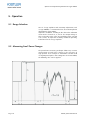
5. Operation ..................................................................................................................................... 18
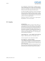
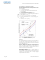
5.1 Range Selection .................................................................................................................. 18
5.2 Measuring Small Force Changes ......................................................................................... 18
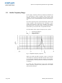
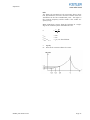
5.3 Usable Frequency Range .................................................................................................... 20
5.4 Temperature Influences ...................................................................................................... 22
5.5 Polarity of the Measuring Signal ......................................................................................... 22
6. Maintenance ................................................................................................................................ 23
6.1 Recalibrating the Instrument .............................................................................................. 23
6.2 Maintenance Tasks ............................................................................................................. 24
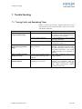
7. Trouble Shooting ......................................................................................................................... 25
7.1 Tracing Faults and Remedying Them .................................................................................. 25
7.2 Defective Dynamometer .................................................................................................... 26
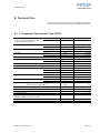
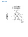
8. Technical Data ............................................................................................................................. 27
8.1 3-Component Dynamometer Type 9255C ......................................................................... 27
8.2 Accessories ......................................................................................................................... 29

Content
9255C_002-615e-02.15 Page 3
9. Annex ........................................................................................................................................... 30
9.1 Glossary .............................................................................................................................. 30
9.2 Measurement Uncertainty .................................................................................................. 34
9.3 Linearity .............................................................................................................................. 35
9.4 Frequency Range ................................................................................................................ 37
9.5 Influence of Temperature .................................................................................................... 38
Total Pages 39

Quartz 3-Component Dynamometer Type 9255C
Page 4 9255C_002-615e-02.15
1. Introduction
Please take the time to thoroughly read this instruction
manual. It will help you with the installation, maintenance,
and use of this product.
To the extent permitted by law Kistler does not accept any
liability if this instruction manual is not followed or prod-
ucts other than those listed under Accessories are used.
Kistler offers a wide range of products for use in measuring
technology:
Piezoelectric sensors for measuring force, torque, strain,
pressure, acceleration, shock, vibration and acoustic-
emission
Strain gage sensor systems for measuring force and
moment
Piezoresistive pressure sensors and transmitters
Signal conditioners, indicators and calibrators
Electronic control and monitoring systems as well as
software for specific measurement applications
Data transmission modules (telemetry)
Kistler also develops and produces measuring solutions for
the application fields engines, vehicles, manufacturing,
plastics and biomechanics sectors.
Our product and application brochures will provide you
with an overview of our product range. Detailed data
sheets are available for almost all products.
If you need additional help beyond what can be found ei-
ther on-line or in this manual, please contact Kistler's ex-
tensive support organization.

Important Information
9255C_002-615e-02.15 Page 5
2. Important Information
2.1 For Your Safety
This instrument has been tested thoroughly and it left
the works in a perfectly safe condition. To maintain
this condition and assure safe operation, the user must
observe the directives and warnings contained in these
instructions
The dynamometer must be installed, operated and
maintained only by persons who are familiar with it
and adequately qualified for their particular tasks
When it must be assumed that safe operation is no
longer possible, the instrument must be taken out of
operation and secured against unintentional use.
It must be assumed that safe operation is no longer
possible if:
the instrument is visibly damaged,
it no longer functions,
it has been in lengthy storage under adverse con-
ditions,
it has received rough treatment during transport
Important!
For measuring cutting forces, fix the dynamometer on the
machine tool according to the instructions. See section
4.2: Assembling the Dynamometer, for details.
Important!
Fix all parts mounted on the top plate of the dynamome-
ter according to the forces expected!

Quartz 3-Component Dynamometer Type 9255C
Page 6 9255C_002-615e-02.15
2.2 How to Treat the Instrument
The dynamometer may be used only under the specified
environmental and operating conditions
The insulation resistance is crucially important with pi-
ezoelectric measurements. It must be around 10
14
Ω
(but at least 10
13
Ω)
To obtain this resistance, all plug and socket connec-
tions must be kept meticulously clean and dry
The insulation resistance can be measured with the
insulation tester Type 5493
Protect the signal output against dirt and do not touch
it with your fingers. When the connection is not being
used, cover it with the cap provided
The connecting cable from dynamometer to charge
amplifier is highly insulating. Use only the proper
cable
Do not remove the connecting cable from the dyna-
mometer
When the dynamometer is not in use, protect it by
keeping it in the packing case supplied
When performing long-time measurements, make sure
that the temperature of the dynamometer remains as
constant as possible

Important Information
9255C_002-615e-02.15 Page 7
2.3 Tips for Using the Instruction Manual
We recommend reading the entire Instruction Manual as a
matter of principle. If you're in a hurry, however, and
you've already gathered experience with Kistler dynamo-
meters, you can confine your reading to the information
that you really need (see section 4).
We have endeavoured to arrange these instructions so that
you can find the information you need without difficulty.
Please keep this Instruction Manual in a safe place where
they can be consulted any time.
If the instructions get lost, just turn to your Kistler customer
service station and they will be replaced without delay.
All information and directives in these instructions may be
modified at any time without prior notification.
2.4 What Happens After Modifications?
Modifications to instruments result in alterations of the
operating instructions as a rule. In such cases, enquire at
your Kistler customer service station about the possibilities
of updating your documentation.
2.5 Disposal Instructions for Electrical and Electronic Equipment
Do not discard old electronic instruments in municipal
trash. For disposal at end of life, please return this prod-
uct to an authorized local electronic waste disposal ser-
vice or contact the nearest Kistler Instrument sales office
for return instructions.

Quartz 3-Component Dynamometer Type 9255C
Page 8 9255C_002-615e-02.15
3. General Description of the Instrument
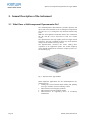
3.1 What Does a Multicomponent Dynamometer Do?
The multicomponent dynamometer provides dynamic and
quasi-static measurement of the 3 orthogonal components
of a force (F
x
, F
y
, F
z
) acting from any direction onto the top
plate.
With the aid of optional evaluation devices the 3 moments
M
x
, M
y
and M
z
can be measured as well (see section
4.4.3).
The dynamometer has high rigidity and hence high natural
frequency. The high resolution enables very small dynamic
changes to be measured in large forces.
The dynamometer measures the active cutting force
regardless of its application point. The usable frequency
range depends mainly on the resonance frequency of the en-
tire measuring rig.
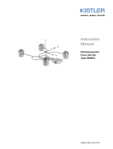
Fig. 1: Dynamometer Type 9255C
Most important applications for the multicomponent dy-
namometer are:
Cutting force measurements while milling and grinding
on larger machines and in machining centers
Measurements on stamping machines
Measurements on wind tunnel models
Measurements of supporting forces at machinery
foundations

General Description of the Instrument
9255C_002-615e-02.15 Page 9
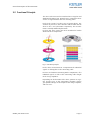
3.2 Functional Principle
The force to be measured is introduced via a top plate and
distributed between four piezoelectric 3-component force
sensors arranged between the base and top plates.
Each of the sensors has three pairs of quartz plates, one
sensitive to pressure in the z direction and the other two to
shear in the x and y directions respectively. The measure
ment is virtually without displacement.
In these four force sensors the force introduced is broken
down into three components.
Fig. 2: Function principle
For the force measurement in 3 components the individual
signals are led together in the connecting cable.
For force and moment measuring with 6 components, all 8
individual signals are led via the connecting cable straight
to the charge amplifiers.
Depending on the direction of the force, positive or nega-
tive charges occur at the connections. Negative charges
give positive voltages at the output of the charge amplifier,
and vice versa.

Quartz 3-Component Dynamometer Type 9255C
Page 10 9255C_002-615e-02.15
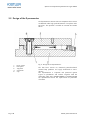
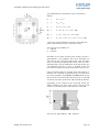
3.3 Design of the Dynamometer
The dynamometer consists of four 3-component force sensors
sandwiched under high preload between a baseplate and a
top plate. This preload is needed to transmit the friction
forces.
Fig. 3: Design of the dynamometer
The four force sensors are mounted ground-insulated.
Ground loop problems are largely eliminated in conse-
quence.
The dynamometer is rustproof and protected against
ingress of splashwater and coolant. Together with the
connecting cable Type 1687B5/1689B5 or 1677A5/1679A5
the dynamometer meets the requirements of protection
class IP67.
1 Force senso
r
2 Base plate
3 Top plate
4 Connector
5 Cap

Assembly, Installation and Putting into Operation
9255C_002-615e-02.15 Page 11
4. Assembly, Installation and Putting into Operation
4.1 Important Remarks
The multicomponent dynamometer Type 9255C is a preci-
sion instrument, but its inherent accuracy can be exploited
and retained only if it is treated with care. The following
rules should therefore be noted:
Never drop the dynamometer or expose it to heavy
impacts! The maximum force of a shock of this kind
could exceed the measuring range of the instrument
and cause permanent deformations
Never use a hammer to position the workpieces, as
such blows might also cause deformation!
On the following pages you will find directions for installing
the dynamometer and basic data for designing the measuring
facility.
4.2 Assembling the Dynamometer
The following directions must be observed if the dyna-
mometer is to be mounted properly:
The dynamometer must be installed only by persons
who are familiar with it and sufficiently qualified for
this work
First the connecting cable has to be mounted. Both
connector sides (dynamometer and cable) have to be
cleaned with Kistler cleansing and insulating spray
Type 1003. To seal the connector the O-Ring is used
(scope of delivery). The mounting surface for the
O-Ring must be clean. The O-Ring is placed properly
and the flange of the cable is mounted onto the
dynamometer by means of two screws (M4x10) and
tightened
Tightening moment = 4,5 N·m
Before mounting the dynamometer on a machine tool
or testing device, make sure that the mounting surface
is flat. Uneven supporting surfaces will cause internal
stresses, which may expose the individual force sensors
to severe additional shear stressing and cause increased
crosstalk
The bottom surface of the dynamometer is ground, i.e.
fine-machined. The instrument should therefore be
mounted on ground or equivalently machined supporting
surfaces
Clean the contact surfaces thoroughly before mounting

Quartz 3-Component Dynamometer Type 9255C
Page 12 9255C_002-615e-02.15
To align the Dynamometer on the machine table one
of the side wall of the flange can be used
Make sure that the dynamometer rests absolutely flat.
Even the smallest air gap will cause undesirable elasticity
and reduce the resonant frequency of the measuring
rig. All mountings must therefore be considered from
the vibration aspect also
Mounting: The dynamometer may be clamped directly
with four M16 bolts (property class 12.9)
Tightening moment for 4 x M16 bolts = 280 N·m
To assure an optimal connection between the dyna-
mometer and the machine, an additional mounting of
the measuring instrument with four M12 screws is rec-
ommended. This is the only way to achieve a high res-
onant frequency and an optimal dynamic behavior
Procedure:
Remove the four lids (position 5 in Fig. 3) on the dy-
namometer top plate
Clamp dynamometer with four M12 (property class
12.9) bolts through the top plate
Tightening moment = 130 N·m
When placing the lids back loosen the vent screw
placed in the center of the lids so that the captured air
can escape. Press lids into their proper position and fix
the vent screws again
Whenever possible, the connecting cable should be left
connected permanently to the dynamometer
4.3 Positioning of the Dynamometer
The dynamometer and the cable are to be positioned
in such a manner that cooling lubricants completely
can drain off. This avoids the formation of aggressive
bacteria in the aged cooling lubricant, damaging the
dynamometer as well as the cable. Accordingly, be-
ware of cavities and corrugations
Lay the connecting cable so that it cannot get cut off
or torn out when working

Assembly, Installation and Putting into Operation
9255C_002-615e-02.15 Page 13
4.4 Basic Circuitry and Cabling of the Measuring System
The electrical charges (in pC) delivered from the measuring
platform are converted by charge amplifiers into propor-
tional voltages, which may be displayed, recorded or
further processed with usual instruments.
The following rules should be observed when cabling the
measuring rig:
The connecting cable from dynamometer to charge
amplifier must have high insulation and low frictional
electricity. Use only the specified cables therefore
Ordinary cables may be used to link the charge ampli-
fiers with the display or evaluation instruments
Make sure that all work with electrical connections is
done carefully and cleanly. Remove the protective caps
from the connections only immediately before connecting
a cable
Cabling instructions for specific configurations are giv-
en in the two sections following

Quartz 3-Component Dynamometer Type 9255C
Page 14 9255C_002-615e-02.15
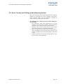
4.4.1 Force Measuring with 3 Components (F
x
, F
y
, F
z
)
The illustration below shows the elements needed to connect
the dynamometer with a multichannel charge amplifier
(e.g. Type 5070Ax01xxx). It is a ground-insulated measur-
ing chain with 3-wire cable.
The connecting cable Type 1687B5/1689B5 and the
extension cable Type 1688B5 are allocated as follows:
Fig. 4: Allocation connecting cable Fig. 5: Allocation extension
Type 1687B5/1689B5 cable Type 1688B5

Assembly, Installation and Putting into Operation
9255C_002-615e-02.15 Page 15
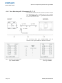
4.4.2 3-Component Force Measurement
The design of a dynamometer ensures that the forces ap-
plied exert no moments on the individual force sensor. The
force sensor can therefore be loaded up to the maximum
defined measuring range (moment-free). With regard to
the zero point of a dynamometer, however, a force vector
whose line of action does not go through this zero point
will produce a moment. Moments cause some of these
sensors to be subjected to an additional load in one or
more directions.
For a 3-component force measurement with a dynamome-
ter consisting of four 3-component sensors, the output sig-
nals (each of Fx, Fy and Fz) of the four sensors are summed.
However, the sum of the four sensors always shows the
correct value irrespective of the force application point.
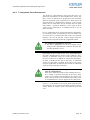
A 3-
c
om
p
onent d
y
namometer measures
the three components of all the resulting forces
acting on the dynamometer and their direction but
not their position in space
Depending on the location of the force application point,
the load is distributed over all four sensors. However, alter-
natively, an individual sensor can receive the main part of
the force. If the force is applied far outside the dynamome-
ter then, according to the law of the lever, an individual
sensor can experience a multiple of the force to be meas-
ured. For applications of this kind, the load on an individual
sensor must be accurately calculated.
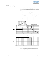
The
f
ollowin
g
rule of thumb a
pp
lies to the measurin
g
range of a dynamometer
If the force application point of the resulting force vec-
tor is within a pyramid consisting of the cover plate
surface and a height corresponding to the shorter side
of the cover plate, then the maximum measuring range
of an individual force sensor applies for the entire plate.
If there is a possibility of the acting loads damaging the
dynamometer, please contact your Kistler Customer Service
Center, where an analysis can be carried out for your load
case.

Quartz 3-Component Dynamometer Type 9255C
Page 16 9255C_002-615e-02.15
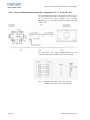
4.4.3 Force and Moment Measuring with 6 Components (F
x
, F
y
, F
z
, M
x
, M
y
, M
z
)
The illustration below shows the elements needed to con-
nect the dynamometer with an multichannel charge ampli-
fier or with several single amplifiers (such as Type
5070Ax1xx). It is a ground-insulated measuring chain with
8-wire cable.
The connecting cable Type 1677A5/1679A5 and the
extension cable Type 1678A5 are allocated as follows:
Fig. 6: Allocation connecting cable Type 1677A5/
1679A5 and extension cable Type 1678A5

Assembly, Installation and Putting into Operation
9255C_002-615e-02.15 Page 17
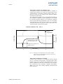
The individual forces and torques can be calculated as
follows:
F
x
= F
x1+2
+ F
x3+4
F
y
= F
y1+4
+ F
y2+3
F
z
= F
z1
+ F
z2
+ F
z3
+ F
z4
M
x
= b ⋅ (F
z1
+ F
z2
– F
z3
– F
z4
) · kM
x
M
y
= a ⋅ (–F
z1
+ F
z2
+ F
z3
– F
z4
) ⋅ kM
y
M
z
= b ⋅ (–F
x1+2
+ F
x3+4
) + a ⋅ (F
y1+4
– F
y2+3
) ⋅ kM
z
a and b are the dynamometer constants in the above for-
mulas, while kM represent the correction factors.
The values for Type 9255C are:
a = 80 mm
b = 80 mm
Deviations occur when measuring the torques because a
dynamometer is not infinitely stiff. These deviations are
corrected by the correction factors kM
x
, kM
y
and kM
z
.
They are normally not provided but must rather be deter-
mined through a special calibration. The design of this spe-
cial calibration must be as close as possible to the real
measurement design to prevent measurement inaccuracies.
If the correction factors are available, then they must be in-
cluded in the calculation. Depending on the characteristics,
the charge amplifiers Type 5070A and 5080A offer the op-
tion to set the correction factors directly. Factor 1 is already
set for the correction factors kM
x
, kM
y
and kM
z
by default.
Depending on the analysis of the measuring results, the
distance between the cover plate surface and the sensor
center is the deciding factor. This distance is called az0.
The value for Type 9255C is: az0 = 48.5 mm
Page is loading ...
Page is loading ...
Page is loading ...
Page is loading ...
Page is loading ...
Page is loading ...
Page is loading ...
Page is loading ...
Page is loading ...
Page is loading ...
Page is loading ...
Page is loading ...
Page is loading ...
Page is loading ...
Page is loading ...
Page is loading ...
Page is loading ...
Page is loading ...
Page is loading ...
Page is loading ...
Page is loading ...
Page is loading ...
-
 1
1
-
 2
2
-
 3
3
-
 4
4
-
 5
5
-
 6
6
-
 7
7
-
 8
8
-
 9
9
-
 10
10
-
 11
11
-
 12
12
-
 13
13
-
 14
14
-
 15
15
-
 16
16
-
 17
17
-
 18
18
-
 19
19
-
 20
20
-
 21
21
-
 22
22
-
 23
23
-
 24
24
-
 25
25
-
 26
26
-
 27
27
-
 28
28
-
 29
29
-
 30
30
-
 31
31
-
 32
32
-
 33
33
-
 34
34
-
 35
35
-
 36
36
-
 37
37
-
 38
38
-
 39
39
-
 40
40
-
 41
41
-
 42
42


Ask a question and I''ll find the answer in the document
Finding information in a document is now easier with AI
Related papers
-
 Kistler 9119AA1 Owner's manual
-
 Kistler 9139AA Owner's manual
-
 Kistler 9257B Owner's manual
-
 Kistler 9253B21 Owner's manual
-
 Kistler 9129AA Owner's manual
-
 Kistler 9272 Owner's manual
-
 Kistler 9236A1 Owner's manual
-
 Kistler 9109AA Owner's manual
-
 Kistler 9129AA Owner's manual
-
 Kistler 9366CDsp Owner's manual


Other documents
-
Ohlins 07430-02 Owner's manual
-
Powerware Horsepower Computer System ST-2400S User manual
-
-
Dynojet 200 Upgrade Manual
-
Vernier Go Direct User manual
-
Lafayette 01165 Lafayette Hand Held Dynamometer Operating instructions
-
NeuLog NUL-237 User guide
-
MAHA MSR 400 Operating instructions
-
 WUNDER RS 300 User manual
-
