Page is loading ...

1
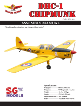
Specications:
Wingspan----------------- 81 in---------------------- 205 cm.
Wing area----------------- 1222.2 sq.in------------- 72.4 sq.dm.
Weight--------------------- 20.9 lbs------------------- 9.5 kg.
Length--------------------- 62.5 in-------------------- 158.8 cm.
Engine size---------------- 40 - 60cc gasoline engine.
Motor 360/ 6000watt/ ESC 160A-200A/ Lipi 12s.
Electric propeller 24x10 - 25x12.
Radio----------------------- 6 channels with 6 digital servos.
ASSEMBLY MANUAL
Code : SEA390

GILMORE RED LION RACER 40-60cc Instruction Manual.
2
1
5
9
8
2 2
ank you for choosing the GILMORE RED LION RACER 40-60cc ARTF by SG MOD-
ELS . e GILMORE RED LION RACER 40-60cc was designed with the intermediate/ad-
vanced sport yer in mind. It is a semi scale airplane which is easy to y and quick to as-
semble. e airframe is conventionally built using balsa, plywood to make it stronger than
the average ARTF, yet the design allows the aeroplane to be kept light. You will nd that
most of the work has been done for you already. e motor mount has been tted and the
hinges are pre-installed. Flying the GILMORE RED LION RACER 40-60cc is simply a joy.
is instruction manual is designed to help you build a great ying aeroplane. Please read
this manual throughly before starting assembly of your GILMORE RED LION RACER
40-60cc Use the parts listing below to indentify all parts.
Please be aware that this aeroplane is not a toy and if assembled or used incorrectly it is ca-
pable of causing injury to people or property. WHEN YOU FLY THIS AEROPLANE YOU
ASSUME ALL RISK & REPONSIBILITY.
If you are inexperienced with basic R/C ight we strongly recommend you contact your R/C
supplier and join your local R/C model Flying Club. R/C Model Flying Clubs oer a variety
of training procedures designed to help the new pilot on his way to successful R/C ight.
ey will also be able to advise on any insurance and safety regulations that may apply.
INTRODUCTION
WARNING
KIT CONTENTS
3
3
6
710
11
4

3
KIT CONTENTS
SEA390 GILMORE RED LION RACER
40-60cc
1. Fuselage
2. Wing set (2)
3. Tail set (2)
4. Canopy
5. Cowling
6. Wing tube
7. Pilot
8. Wheel pants
9. landing gear
10. Fuel tank
11. Tail wheel
ADDITIONAL ITEMS REQUIRED
TOOLS & SUPPLIES NEEDED
in cyanoacrylate glue.
Medium cyanoacrylate glue.
30 minute epoxy.
5 minute epoxy.
Hand or electric drill.
Assorted drill bits.
Modelling knife.
Straight edge ruler.
2mm ball driver.
Phillips head screwdriver.
220 grit sandpaper.
90° square or builder’s triangle.
Wire cutters.
Masking tape & T-pins.
read-lock.
Paper towels.
� 40-60cc gasoline engine.
� Computer radio 6 channel with 6
servos.
� Glow plug to suit engine.
� Propeller to suit engine 24x10 -
25x12.
� Protective foam rubber for radio
system.
INSTALL THE AILERONS
Please see pictures below.
3.
2.
1.
Use a small piece of rough sandpaper to
scu the hinges for better epoxy adhesion.
Do this to all aileron hinges.
Remove the ailerons from the wing and
remove the hinges.
Apply epoxy to each hinge where it will
be inserted into the ailerons. Tip: Apply
some petroleum jelly to the metal pin
hinge area to keep epoxy from interfering
with smooth operation of hinge.
Epoxy

GILMORE RED LION RACER 40-60cc Instruction Manual.
4
1.
INSTALL THE AILERONS
CONTROL HORN
Fiberglass control horn
5.
4.
Insert all four hinges in the ailerons at
this time. Make sure hinges move up and
down in right direction and not side to
side !
Epoxy
6.
Apply epoxy into each of the holes in the
ailerons using a spare piece of pushrod
wire or toothpick.
Make sure to use enough epoxy so it
securely adheres the hinge to the surfaces.
Do not use an excessive amount of epoxy
when gluing the hinges so that it expels
from the hinge area.
7.
8.
Be sure to test the aileron hinges once
you insert them. Ensure that the hinge
pockets line up, and that the hinges move
freely before the epoxy dries.
Check the t of the aileron to the wing.
e top of the ailerons will align to the
top of the wing. Make sure movement is
smooth and bind free.
We prefer 30-minute epoxy to allow
enough working time during the hinge
installation.
Epoxy

5
1.
2.
3.
2.
3.
4.
Fiberglass control horn
INSTALLING THE AILERON SERVOS
Epoxy
Epoxy
Because the size of servos dier, you
may need to adjust the size of the precut
opening in the mount. e notch in the
sides of the mount allow the servo lead to
pass through.
Place the servo between the mounting
blocks and space it from the hatch. Use a
pencil to mark the mounting hole loca-
tions on the blocks.
4.
Use drill bit in a pin vise to drill the
mouting holes in the blocks.
1.5mm
Maximum Servo spec.
Torque : 126.6 oz-in (9.11 kg-cm) @ 6.0V;
178 oz-in (12.82 kg-cm) @ 7.4V; 248 oz-
in (17.86 kg-cm) @ 8.4V

GILMORE RED LION RACER 40-60cc Instruction Manual.
6
8.
9.
10.
11.
5.
6.
7.
Use dental oss or heatshrunk tube to
secure the connection so they cannot be-
come unplugged.
Secure the servo to the aileron hatch
using Phillips screwdriver and the screws
provided with the servo.
Apply 1-2 drops of thin C/A to each
of the mounting tabs. Allow the C/A to
cure without using accelerator.
Apply 2-3 drops of thin C/A to each
of the mounting holes. Allow the C/A to
cure without using accelerator.
C/A glue
Remove the string from the wing at the
servo location and use the tape to attach it
to the servo extension lead. Pull the lead
through the wing and remove the string.
C/A glue

7
1.
2.
3.
12.
13.
14.
Set the aileron hatch in place and use a
Phillips screw driver to install it with four
wood screws.
AILERON PUSHROD INSTALLATION
Please see below pictures.
3x10mm
120mm
80mm
M3 clevis. M3 lock nut.
Secure the servos with the screws pro-
vided with your radio system.
.
INSTALLING THE FUSELAGE SERVOS
.
Because the size of servos dier, you
may need to adjust the size of the precut
opening in the mount. e notch in the
sides of the mount allow the servo lead to
pass through.
Install the rubber grommets and brass
collets into all servos. Test t the servos
into the fuselage servo mounts.

GILMORE RED LION RACER 40-60cc Instruction Manual.
8
3.
1.
2.
1.
2.
1.
2.
INSTALLING LANDING GEAR
Locate items necessary to install Sprin
Landing Gear.
INSTALLING THE RECEIVER SWITCH
Install the switch into the precut hole in
the side, in the fuselage.
3/32” Hole
Elevator servo
Elevator servo
.
Switch.
INSTALLING THE ENGINE SWITCH
Trim and cut
Switch
Trim and cut
Elevator servo arm
Elevator servo arm
rottle servo arm
Rudder servo
rottle servo
Rudder servo arm

9
5.
6.
7.
8.
1.
2.
3.
4.
M4x15mm

GILMORE RED LION RACER 40-60cc Instruction Manual.
10
13.
14.
15.
16.
9.
10.
11.
12.
M3x4mm

11
21.
22.
23.
17.
18.
19.
20.
13
24.

GILMORE RED LION RACER 40-60cc Instruction Manual.
12
29.
30.
31.
25.
26.
27.
28.INSTALLING THE STOPPER
ASSEMBLY
Using a modeling knife, carefully cut
o the rear portion of one of the 3 nylon
tubes leaving 1/2” protruding from the
rear of the stopper. is will be the fuel
pick up tube.
M4x12mm Loctite

13
1.
1.
2.
3.
Using a modeling knife, cut one length
of silicon fuel line. Connect one end of
the line to the weighted fuel pick up and
the other end to the nylon pick up tube.
FUEL TANK INSTALLATION
Carefully bend the second nylon tube up at
a 45º angle. is tube is the vent tube.
Test t the stopper assembly into the tank.
It may be necessary to remove some of the
ashing around the tank opening using a
modeling knife. If ashing is present, make
sure none falls into the tank.
When satised with the alignment of the
stopper assembly tighten the 3x20mm ma-
chine screw until the rubber stopper expands
and seals the tank opening. Do not overtight-
en the assembly as this could cause the tank
to split.
With the stopper assembly in place, the
weighted pick-up should rest away from the
rear of the tank and move freely inside the
tank. e top of the vent tube should rest just
below the top of the tank. It should not touch
the top of the tank.
Vent tube.
Fuel ll tube.
Fuel pick up tube.
You should mark which tube is the vent
and which is the fuel pickup when you attach
fuel tubing to the tubes in the stopper. Once
the tank is installed inside the fuselage, it may
be dicult to determine which is which.
2.
Slide the fuel tank into the fuselage. Guide
the lines from the tank through the hole in
the rewall.

GILMORE RED LION RACER 40-60cc Instruction Manual.
14
1.
5.
6.
7.
3.
4.
Connect the lines from the tank to the en-
gine and muer. e vent line will connect
to the muer and the line from the clunk to
the carburetor.
Blow through one of the lines to en-
sure the fuel lines have not become kinked
inside the fuel tank compartment. Air should
ow through easily.
MOUNTING THE ENGINE
Please see pictures below
M3x15mm
Fuel pick up tube Fuel ll tube
Vent tube

15
6.
Locate the engine mounting in position on
the rewall. Use a 6.1mm drill bit to drill the
holes necessary to mount your particular
motor choice.
7.
8.

GILMORE RED LION RACER 40-60cc Instruction Manual.
16
13.
14.
15.
16.
9.
10.
11.
12.
Position the engine with the drive washer
(172mm) forward of the rewall.
172mm
6.1mm

17
17.21.
18.
22.
19.
23.
20.24.
Attach the muer to the engine using
the hardware included with the muer.
Ignition Module

GILMORE RED LION RACER 40-60cc Instruction Manual.
18
26.
27.
28.
29.
25.
Use medium CA to glue the pushrod
stando to the inside of the fuselage and
the pushrod tube.
Reinstall the servo horn by sliding the
connector over the pushrod wire. Cent-
er the throttle stick and trim and install
the servo horn perpendiular to the servo
center line.
1.
DUMMY ENGINE
Move the throttle stick to the closed po-
sition and move the carburetor to closed.
Use a 2.5mm hex wrench to tighten the
screw that secures the throttle pushrod
wire. Make sure to use threadlock on the
screw so it does not vibrate loose.
Please see below pictures.
Epoxy

19
4.
5.
6.
7.
2.
3.
4mm
8.
9.
Epoxy

GILMORE RED LION RACER 40-60cc Instruction Manual.
20
12.
13.
14.
1.
10.
11.COWLING
2.
3.
/