Page is loading ...

Solenoid Operated Block Valves
A2800 Series
Installation and Parts
Liquid ControLs An IDEX Fluid & Metering Business
Installation: M400-40

2
TABLE OF CONTENTS
The most current English versions of all Liquid Controls publications are available on our web site, www.lcmeter.com. It is the
responsibility of the local distributor to provide the most current version of LC manuals, instructions, and specication sheets in
the required language of the country, or the language of the end user to which the products are shipping. If there are questions
about the language of any LC manuals, instructions, or specication sheets, please contact your local distributor.
Publication Updates and Translations
! WARNING
• Before using this product, read and understand the instructions.
• All work must be performed by qualied personnel trained in the proper application, installation, and
maintenance of equipment and/or systems in accordance with all applicable codes and ordinances.
• When handling electronic components and boards, always use proper Electrostatic Discharge (ESD) equipment
and follow the proper procedures
• Make sure that all necessary safety precautions have been taken.
• Provide for proper ventilation, temperature control, re prevention, evacuation, and re management.
• Provide easy access to the appropriate re extinguishers for your product.
• Consult with your local re department, state, and local codes to ensure adequate preparation.
• Read this manual as well as all the literature provided in your owner’s packet.
• Save these instructions for future reference.
• Failure to follow the instructions set forth in this publication could result in property damage, personal injury, or
death from re and/or explosion, or other hazards that may be associated with this type of equipment.
Be Prepared
INTRODUCTION
Safety Procedures ................................................... 3
A2800 Series Block Valve Overview ........................ 3
Specications ........................................................... 4
INSTALLATION
New Installations ...................................................... 4
Retrot Installations .................................................. 5
A2843 Valve
Single-Stage LPG Application .................................. 6
A2859-11 Valve
Two-Stage LPG Applications .................................... 7
A2847-11 Valve
Single-Stage Rened Fuel Applications ................... 8
A2848-11 Valve
Two-Stage Rened Fuel Applications ...................... 9
Disassembly Kit ....................................................... 10
ILLUSTRATED PARTS BREAKDOWN
A2843 Valve Assembly ............................................ 11
82102 & 82102-24 Solenoid Kit .............................. 12
A2859-11 Two-Stage Valve ..................................... 13
A2847-11 Single Stage Valve .................................. 14
A2848-11 Two-Stage Valve ..................................... 15

3
SAFETY PROCEDURES
A2800 Series Block Valve Overview
The Liquid Controls A2800 Series Solenoid Operated Block Valves are designed for use with LectroCount electronic
registers. Four models are available:
A2843
Single-stage valve with overmolded, soft-seat piston; braided metal solenoid
hoses and a 3-way solenoid (Model 82102 or 82102-24); used in LPG
applications.
A2859-11
Two-stage preset version incorporates a 2-way, “bypass” solenoid added to
the A2843 valve for precise “0” shut-off and to prevent hydraulic shock. The A2859-11 two-stage, solenoid operated block valve is
used for LPG applications.
A2847-11
Single-stage valve with overmolded, soft-seat piston; ared copper solenoid tubing; and a 3-way solenoid. Used for rened fuels
applications where a single stage, solenoid operated block valve function is required.
A2848-11
Two-stage preset version incorporates a 2-way, “bypass” solenoid added to the A2847-11 valve for precise “0” shut-off and hydraulic
shock prevention. The A2848-11 two-stage, solenoid operated block valve is used for rened fuels applications.
Metallurgical and seal material changes may
be needed for other applications (example:
methanol). Consult factory if your application
is not listed in the descriptions of A2800 series
solenoid operated block valves shown here.
! WARNING
Power, input, and output (I/O) wiring must be in accordance with the area classication for which it is used. This may
require using connections or other adaptations in accordance with the requirements of the authority having jurisdiction.
WARNING: Explosion Hazard -
• Substitution of components may impair suitability for Class I, Division 2 applications.
• When in hazardous locations, turn power OFF before replacing or wiring modules.
• Do NOT disconnect equipment unless power has been switched OFF or the area is known to be Non-Hazardous.
Observe National and
Local Codes
Before disassembly of any meter or accessory component:
ALL INTERNAL PRESSURES MUST BE RELIEVED AND ALL LIQUID DRAINED FROM THE
SYSTEM IN ACCORDANCE WITH ALL APPLICABLE PROCEDURES.
-Pressure must be 0 (zero) psi.
-Close all liquid and vapor lines between the meter and liquid source.
Failure to follow this warning could result in property damage, personal injury, or death from re and/or explosion, or other
hazards that may be associated with this type of equipment.
! WARNING
Safely Evacuate
Piping System

4
SPECIFICATIONS
Specications
Temperature Range
•-40 to 160 °F (-40 to 71 °C)
Pressure Rating
LPG
Maximum non-shock working pressure
• 350 PSI (24 BAR)
Maximum differential pressure
• 125 PSI (86 BAR)
Refined Fuels
Maximum non-shock working pressure
• 150 PSI (10 BAR)
Maximum differential pressure
• 100 PSI (69 BAR)
Materials of Construction
Main valve body and bonnet/cap
• A3560 anodized aluminum
Main valve internal trim
• Anodized aluminum, brass, plated steel
Elastomers
Valve diaphragm and 0-ring seals standard
• Buna-N UL approved
Solenoids Output
Voltage
10.2 to 27.2 VDC
Current
1 A maximum
Regulatory
Explosion-proof, UL approved for NEMA 7 requirements
for Class I, Division 2, Group C and D hazardous
locations
New Installations
When ordered with a new meter, the A2800 Series solenoid operated block valves are mounted to the meter at the
factory. The valve solenoids are prewired to the LectroCount electronic register and optical or vapor eliminators (if
included in system) at the factory. Connect the system piping to the 2” NPT ange on the outlet side of the block
valve.
MODEL FLOWRATES AND PRESSURE RATINGS
A2843
• 200 GPM (757 LPM)
• 350 PSI (24 BAR)
A2859-11
• 200 GPM (757 LPM)
• 350 PSI (24 BAR)
A2847-11
• 200 GPM (757 LPM
• 150 PSI (10 BAR)
A2848-11
• 200 GPM (757 LPM)
• 150 PSI (10 BAR)
M-7 Flowmeter with block valve (no solenoids), optical
vapor eliminator, strainer, and LectroCount LCR-II

5
INSTALLATION
Retrot Installations
Depending on the existing conguration, adding a block valve may require modication of the outlet piping. After the
internal pressure is relieved from the system, the outlet line can be disconnected from the mechanical valve being
replaced. The new valve assembly can then be connected to the outlet side of the positive displacement meter. Use
the four bolts and washers to fasten the valve assembly to the meter. The valve has an arrow showing the direction
of ow. Ensure that the valve is properly oriented. Tighten the bolts in a crossing pattern. Once this is complete, the
outlet piping may be reconnected to the outlet side of the differential preset valve. The valve outlet tting is 2” NPT.
Wiring instructions for each of the models is covered on pages 6-9.
LectroCount LCR-II
Gallons
S3
Block Valve
2-stage preset
LectroCount
Electronic Register
Air Eliminator optical
Strainer high capacity
Flowmeter
Before disassembly of any meter or accessory component:
ALL INTERNAL PRESSURES MUST BE RELIEVED AND ALL LIQUID DRAINED FROM THE SYSTEM IN
ACCORDANCE WITH ALL APPLICABLE PROCEDURES.
-Pressure must be 0 (zero) psi.
-Close all liquid and vapor lines between the meter and liquid source.
Failure to follow this warning could result in property damage, personal injury, or death from re and/or
explosion, or other hazards that may be associated with this type of equipment.
! WARNING

6
A2843 VALVE - SINGLE-STAGE LPG APPLICATIONS
ELECTRICAL SEQUENCING
Supply voltage to the LectroCount LCR
or LCR-II must be +24 VDC when using
the 82102-24 Solenoid Kit.
! WARNING
** SOLENOID WARNING: The earth ground to the green screw on the solenoid terminal
block is not essential for the operation of the device. In a truck application the solenoid
is automatically grounded to the truck chassis via the liquid carrying piping. Check any
applicable electrical codes to comply with proper grounding procedures.

7
ELECTRICAL SEQUENCING
! WARNING
** SOLENOID WARNING: The earth ground to the green screw on the solenoid terminal
block is not essential for the operation of the device. In a truck application the solenoid
is automatically grounded to the truck chassis via the liquid carrying piping. Check any
applicable electrical codes to comply with proper grounding procedures.
TWO-STAGE LPG APPLICATIONS - A2859-11 VALVE

8
A2847-11 VALVE - SINGLE-STAGE REFINED FUEL APPLICATIONS
ELECTRICAL SEQUENCING
! WARNING
** SOLENOID WARNING: The earth ground to the green screw on the solenoid terminal
block is not essential for the operation of the device. In a truck application the solenoid
is automatically grounded to the truck chassis via the liquid carrying piping. Check any
applicable electrical codes to comply with proper grounding procedures.

9
ELECTRICAL SEQUENCING
TWO-STAGE REFINED FUEL APPLICATIONS - A2848-11 VALVES
! WARNING
** SOLENOID WARNING: The earth ground to the green screw on the solenoid terminal
block is not essential for the operation of the device. In a truck application the solenoid
is automatically grounded to the truck chassis via the liquid carrying piping. Check any
applicable electrical codes to comply with proper grounding procedures.

10
DISASSEMBLY - DISASSEMBLY KIT
Disassembly Kit
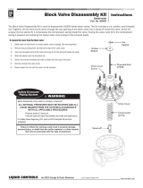
The Block Valve Disassembly Kit is used to disassemble A2800 Series block valves. The kit includes a nut, washer,
and threaded rod. Together, the kit items screw down through the top opening of the block valve into a stand-off inside
the valve. As the kit screws into the stand-off, it compresses the compression spring inside the valve, freeing the valve
cover form the compression spring’s pressure and allowing the twelve valve cover screws to be removed easily.
To remove the cover from the block valve:
1. Safely drain all liquid from the meter system (and all piping). See warning
below.
2. Remove any plumbing from the hole at the top of the valve cover.
2. Insert the threaded rod into the hole and screw it into the stand-off inside the
valve.
3. Slide the washer over the threaded rod.
4. Screw nut onto the threaded rod until it is ush with the top of the cover.
5. Remove screws from valve cover.
6. Slowly loosen the nut until the cover can be removed.
Nut
06055
Washer
06663
Stand-off
Threaded Rod
47098
Compression
Spring
Valve Cover
Valve Cover
Screws
Before disassembly of any meter or accessory component:
ALL INTERNAL PRESSURES MUST BE RELIEVED AND ALL
LIQUID DRAINED FROM THE SYSTEM IN ACCORDANCE
WITH ALL APPLICABLE PROCEDURES.
-Pressure must be 0 (zero) psi.
-Close all liquid and vapor lines between the meter and liquid source.
Failure to follow this warning could result in property damage,
personal injury, or death from re and/or explosion, or other hazards
that may be associated with this type of equipment.
! WARNING
Safely Evacuate
Piping System

11
ILLUSTRATED PARTS BREAKDOWN - A2843 VALVE ASS’Y
*N/S = Not for Sale
A2843 Valve Assembly
Items specic to the 49971 and 501339 assemblies are indicated as
such.
Item # Part # Description
110 47096 Valve Housing Assembly
124 47302 Valve Cover
130 49947 Piston
225 N/S* Piston Guide Shaft
(Part of 47096 Assembly)
235
47305 Compression Spring
[A2843, 501339 only]
49970 Compression Spring
[49971 only]
245 47307 Spring Retainer
255 47308 Back-up Plate (2)
265 47309 Stand-off
275 47098 Rod Assembly
325 502078 Diaphragm
335 06856 Buna-N O-Ring
340 07900 Buna-N O-Ring
345 07838 Buna-N O-Ring
510 06055 Nut
540 N/S Nameplate
565 04759 Pipe Plug (4)
610 04655 Screw (12)
615 06851 Screw (4)
678 00306S Screw (2)
710 09360 Flat Washer (12)
715 04498 Flat Washer (4)
720 06070 Lock Washer
735 06663 Flat Washer
Disassembly Kit

12
ILLUSTRATED PARTS BREAKDOWN - 82102 & 82102-24 SOLENOID KIT
82102 & 82102-24 Solenoid Kit
These two items are used with model A2843 in LPG applications.
Item # Part # Description
181527 3-way Solenoid Valve Assembly +12 VDC for use with 82102
81554 3-way Solenoid Valve Assembly +24 VDC for use with 82102-24
781585 Hose Assembly Not available for NH3 applications

13
*N/S = Not for Sale
A2859-11 TWO-STAGE VALVE - ILLUSTRATED PARTS BREAKDOWN
2 Places
S2
170
125
160
115 715615
345
4 Places
A2859-11 Two-Stage Valve
Item # Part # Description
115 501339 Block Valve Assembly See page 11
for 501339 breakdown
125 501536 2-way Solenoid Valve
160 09413 Pipe Nipple
170 501535 Hose Assembly
215 N/S* Pipe Plug (2)
220 N/S Male Elbow (2)
230 N/S Pipe Nipple
235 09414 Pipe Elbow
240 09412 Male Elbow
245 09411 Expander/Adapter
275 47098 Rod Assembly
345 07838 Buna-N O-Ring
510 06055 Nut
615 06851 Screw (4)
715 04498 Flat Washer (4)
735 06663 Flat Washer
The A2859-11 LPG Two-Stage Valve comes with the following kits:
82584 S1 Solenoid Kit (3-way solenoid with brass bittings and hoses)
3-way Solenoid Valve Assembly can be ordered as a single
part as Part Number 81868
81859 Two-Stage Cable Kit.
A2859-11 LPG Two-Stage Valve Kits

14
A2847-11 Single Stage Valve
Item # Part # Description
115 49971 Block Valve Assembly See page 11
for 49971 breakdown
120 49986 3-way Solenoid Valve Assy.
130 49975 Tubeline Assembly
140 49976 Tubeline Assembly
150 49977 Tubeline Assembly
210 N/S* Pipe Thread Reducer (2)
215 N/S Pipe Plug (2)
220 N/S Male Elbow (2)
230 N/S Male Elbow
345 07838 Buna-N O-Ring
615 06851 Screw (4)
715 04498 Flat Washer (4)
*N/S = Not for Sale
ILLUSTRATED PARTS BREAKDOWN - A2847-11 SINGLE STAGE VALVE

15
A2848-11 Two-Stage Valve
Item # Part # Description
115 49971 Block Valve Assembly See page 11
for 49971 breakdown
120 49980 3-way Solenoid Valve
125 49981 2-way Solenoid Valve
130 49975 Tubeline Assembly
140 49976 Tubeline Assembly
150 49977 Tubeline Assembly
160 49978 Tubeline Assembly
170 49979 Tubeline Assembly
210 N/S* Pipe Thread Reducer (2)
220 N/S Male Elbow (2)
230 N/S Male Elbow
240 N/S Male Elbow (2)
345 07838 Buna-N O-Ring
615 06851 Screw (4)
715 04498 Flat Washer (4)
*N/S = Not for Sale
A2848-11 TWO STAGE VALVE - ILLUSTRATED PARTS BREAKDOWN

© 2008 Liquid Controls
Pub. No. 500056
(6/14)
105 Albrecht Drive
Lake Bluff, IL 60044-2242
1.800.458.5262 • 847.295.1050
Fax: 847.295.1057
/


