Page is loading ...

MagnaPower
®
Installation, Operation, and
Maintenance Manual

Table of Contents
Section Page
1 Safety ........................................................ 1
2 General Information............................................2-3
3 Installation ...................................................4-9
4 Operation..................................................10-11
5 Maintenance ...............................................12-15
6 Service ....................................................16-34
7 Troubleshooting.............................................35-42
8 Generator Testing ...........................................43-46
9 Special Tools ...............................................47-48
10 Preparation for Shipment or Storage .............................. 49
11 Specification and Data........................................50-51
Generator Formulas............................................ 52
Warnings & Cautions ...............................Inside Back Cover

Section 1 Safety
PLEASE REMEMBER SAFETY FIRST. If you are not
sure of the instructions or procedures, seek qualified
help before continuing.
This service manual emphasizes the safety pre-
cautions necessary during the installation, operation
and maintenance of the MAGNAPOWER
®
generator.
Each section has caution and warning messages.
These messages are for your safety and the safety
of the equipment involved. If any of the cautions or
warnings are not readily understood, seek clarification
from qualified personnel before proceeding.
Before any service work is done, disconnect all power
sources and, where appropriate, lock out all controls
to prevent an unexpected start-up of the generator
set. Proper grounding in compliance with local and
national electrical codes must be provided. These
safety precautions are necessary to prevent potential
serious personal injury, or even death.
The hazards associated with lifting or moving the
MAGNAPOWER
®
generator are pointed out in the
installation and service sections; incorrect lifting or
moving can result in personal injury or property
damage.
Whenever the generator is running, always assume
and proceed as if voltage is present. Residual
voltage is present at the generator leads and at the
regulator panel connections, even with the regulator
fuse removed. Caution must be observed. Otherwise,
serious personal injury or death can result.
Whenever solvents, cleaners, or flammable liquids are
present, adequate ventilation must be available to
avoid fire, explosion, and health hazards. Always avoid
breathing vapors and use suitable personal protective
equipment to prevent personal injuries (such as eyes,
face, and hand protection).
This manual is not intended to be a substitute for
properly trained personnel. Repairs should only be
attempted by qualified, trained people. The cautions
and warnings point out known conditions that are
potentially dangerous. Each installation will create its
own set of circumstances. No manual can cover every
possible situation.
When in doubt, ask. Don’t be embarrassed to ask
“dumb questions.” Remember, dumb questions are
much easier to handle than dumb mistakes.
A Few Words About Safety
1
The following statement is only applicable to high voltage generators (above 5000 V). A
grounding strap is supplied from the generator neutral to ground. This grounding strap not only bleeds off
any voltage potential on the main stator after the high potential test, but also bleeds off any static charge that
can build-up on the main stator during shipment and storage. THIS GROUND STRAP IS NOT A PERMANENT
PART OF THE GENERATOR CONSTRUCTION. REMOVE THIS GROUND STRAP ONLY AFTER A PERMANENT
GROUND IS INSTALLED ON THE GENERATOR MAIN STATOR (not supplied by Marathon Electric), OR THE
GENERATOR FINAL INSTALLATION IS COMPLETE.

General Information Section 2
General
All single and two bearing units are manufactured with
cast iron end brackets and adapters and fabricated
steel frames. Flexible drive discs and SAE adapters
are machined to SAE standards. Prelubricated,
regreasable, shielded ball bearings are used on
MAGNAPOWER
®
generators.Standard units are fully
guarded. Dripproof shields are available as an option.
Conduit Box
Assembly is optimized for customer flexibility. Various
access panels and a low voltage control section are
provided. The external load leads can enter the conduit
box from the top, bottom, or side. Furthermore, the
conduit box is designed to accept various auxiliary
devices (potential and current transformers, etc.) while
maintaining a compact generator outline. All models
are equipped with an end-mounted conduit box as
standard. Optional conduit box designs are available
to meet customer requirements.
MAGNAPOWER
®
Uni-rotor Construction
Laminations are 4-pole, one piece laminations which
are shrunk fit and keyed to the shaft. No dovetails,
cross bolts or other pole to shaft connecting devices
are used. An amortisseur winding is standard. The cast
unidirectional aluminum alloy ventilating fan provides
even air distribution to maximize cooling and genera-
tor efficiency.
Adapters and Drive Discs
All single bearing units are available with several
adapter and drive disc arrangements. These can be
shipped to order or can be changed in the field with
standard shop tools. When changing flexible drive
discs, spacers are used between the discs and the cast
iron hub to maintain SAE standard dimensions.
Electrical Design
General
All standard products have 2/3 pitch main windings
to eliminate the third harmonic. This serves to lower
operating temperatures, give lower harmonic content
and better wave form, and extend the overall life of the
generator. The phase sequence is ABC when rotated
counterclockwise viewing exciter end.
Temperature Rise
All ratings and frame sizes are based on NEMA Class
F and Class H temperature rises on both the rotor and
stator windings. Ratings for British, German, French,
IEC, and all popular marine agencies are available.
Standby Generator
Synchronous generators used on emergency backup
power can have temperature rises up to 25°C above
those for continuous operation (NEMA MG1-22.40
and MG 1-22.84).
Premium Insulation System
All MAGNAPOWER
®
generators are built with Class F
or better insulation materials. All standard generators
are suitable for continuous duty at Class F tempera-
ture rise and will give equivalent or better winding life
expectancy to generators supplied with Class A or B
insulation systems operated within their temperature
limits. MAGNAPOWER
®
generators are manufactured
with an epoxy Vacuum Pressure Impregnated (VPI)
insulation system and form-wound coils, which make
the standard winding fungus-resistant and suitable
for high humidity and abrasive environments. The
MAGNAPOWER
®
rotor is wet-wound with thermo-
setting epoxy applied between each layer, plus a final
coating of epoxy for moisture and abrasion resistance.
Power Factor
All standard generators are designed for operation
at rated kVA at 0.8 lagging power factor but can
be operated at rated kVA over the 0.8 to 1.0 power
factor range.
DVR
®
Voltage Regulator
The standard voltage regulator is a fully encapsulated,
static type with a solid state build up circuit. Standard
features include 3 phase RMS sensing, paralleling,
adjustable underfrequency protection, and overexcita-
tion protection. The regulator meets EMI suppression
to Mil Std-461C, part 9. An optional feature is adjustable
armature current limiting. See the regulator manual
for more information.
Mechanical Design
2

It is extremely important to properly identify the
machine when requesting parts or service.
Always have available the generator model number
and serial number when requesting information from
the factory. We cannot help you without this infor-
mation. It is also beneficial to know the mounting
arrangement code.
An Example for MAGNAPOWER
®
Generators
Example: 1020 FSL 5000
Frame Number
F – Form Wound
S – 1 Bearing
D – 2 Bearings
L – Up to 480 volts
S – 600 volts
M – 1000-6600 volts
H – 6900-13,800 volts
Style
Type
¬ Á ® ¯ ° Å
¬
Á
®
¯
°
Å
Section 2 General Information
How to Read a Model Number
3

4
Installation Section 3
Receiving Your MAGNAPOWER
®
Generator
Upon receipt of the generator, it is recommended that
it be carefully examined for possible damage incurred
in shipment. The generator was given to the freight
company in good condition, and they are responsible
for the product from our dock to yours. Any damage
should be noted on the freight bill before accepting
the shipment. Claims for damage must be promptly
filed with the freight company.
Unpacking and Handling
Read all instruction cards carefully. When lifting, attach
an overhead crane to the lifting lugs on the generator
frame. Apply lifting forces in a vertical direction.
The lifting lugs on the generator are
designed to support the generator only. Do not lift
complete generator set by means of lifting lugs on
generator. Personal injury or equipment damage
may result.
Storage
In the event that the generator is not to be installed on
the prime mover immediately, it is recommended that
it be stored in a clean, dry area which is not subject
to rapid changes in temperature and humidity. See
Section 10 for more information.
Preparation for Use
Although the generator is carefully inspected and
tested in operation before it leaves the factory, it is
recommended that the unit be thoroughly inspected.
The insulation on the wire should be inspected and all
bolts should be checked for tightness.
Remove all shipping tapes, bags, blocks, and skids
which are used to prevent vibration and rotor move-
ment during shipment. Dry, low-pressure compressed
air of approximately 30 psi (206 KPA) can be used
to blow out the interior of the generator. In the case
of two bearing machines, it is possible to turn the
rotor by hand to make sure that it rotates smoothly
without binding.
If the machine has been in storage for a year or longer,
it is recommended that it be lubricated according to
the lubrication instructions and chart found in Section 5.
If the machine has been exposed to damp, humid
conditions, the insulation resistance should be
checked. Refer to Section 8.
Generator Mounting – Single Bearing
Single bearing generators are provided with an SAE
flywheel adapter and flexible drive discs. Very close
tolerances are maintained in the manufacture of the
generator so that the alignment procedure is extreme-
ly simple. A coupling hub of nodular iron is shrunk onto
the shaft and special steel drive discs are bolted to the
hub. Holes are provided in the periphery of the coupling
disc which correspond to tapped holes in the flywheel.
The outside diameter of the discs fits in a rabbet in the
flywheel so that concentricity is assured in all cases.
Do not apply any force to genera-
tor fan for lifting or rotating generator rotor.
Disregarding these instructions may cause personal
injury or equipment damage.
Grade 8 capscrews and heavy series
lockwashers or grade 8 placebolts and hardened
washers are recommended to mount the drive discs
to the flywheel.
The SAE adapter and the flywheel housing are
designed to match each other with no further alignment
necessary. Shims may be necessary under the feet of
the generator to insure a solid mounting. See Section
6 for more information.
Generator Mounting – Two Bearing
Two bearing generators are provided with a shaft
extension and keyway. For direct-coupled units,
the assembler furnishes a flexible coupling which is
installed between the driver and the generator shaft.
Important: Aligning the two machines as accurately
as possible will reduce the vibration, increase bearing
life, and insure minimum coupling wear. It may be
necessary to shim the generator feet for proper support
and alignment. Consult the coupling manufacturer’s
instructions for alignment specifications and procedures.
4

Section 3 Installation
Environmental Considerations
Dirt, moisture, heat, and vibration are enemies of
electrical equipment. Excessive exposure to the
elements will shorten the life of the generator.
The ambient temperature should not exceed the
value shown on the generator nameplate. The
MAGNAPOWER
®
is built in a NEMA open type
enclosure. Generators for outdoor application should
be protected from the elements by housings with
proper openings for ventilation. This protection should
be designed to prevent the direct contact of wind
driven rain, snow, or dust with the generator. In moist or
humid areas, such as the tropics and marine service,
additional protection is recommended. Although the
standard windings are humidity and moisture resis-
tant, special insulations and accessories such as space
heaters can increase generator life significantly. In
extremely dirty and dusty environments, a means
of providing filtered cooling air to the generator is
recom
mended. Refer to Marathon Electric for more
information.
Electrical Connections
The generator conduit box construction allows conduit
to enter the top, bottom, or either side of the box. A
hole-saw or any suitable tool can be used to provide
for the conduit entrance. Protect the interior of the
generator from shavings when drilling or sawing. An
approved connector must be used in conjunction with
the conduit.
To minimize the transmission of vibration, it is essen-
tial that flexible conduit be used for all electrical
entrance to the generator.
Refer to the connection diagram supplied with the
generator and/or the proper diagrams shown in this
section. Install all intercomponent and external wiring
in accordance with the regulations of the national
and local electrical codes. Clean all contact surfaces
to assure good electrical bonding with the generator
lugs or bus bars. Use heavy duty terminal lugs or good
quality clamps for making all connections. Insulate
all connections in accordance with national and local
regulations.
Be sure the generator frame is grounded to all the
other components of the system with a ground wire in
accordance with national and local regulations.
Generator Lead Connections
The electrical connections in the conduit box should
be made in accordance with the appropriate “connection
diagram.” Use the diagram appropriate for the number
of leads and voltage range required. Refer to the draw-
ings
supplied with the generator and to drawings in this
section.
The final voltage setting is established within the selected
range by an adjustment of the voltage regulator.
Some generators have multiple, iden-
tically marked cables for each lead. Connect all
identically marked cables together when making
connections.
5
The following statement is only applicable to high voltage generators (above 5000 V). A
grounding strap is supplied from the generator neutral to ground. This grounding strap not only bleeds off
any voltage potential on the main stator after the high potential test, but also bleeds off any static charge that
can build-up on the main stator during shipment and storage. THIS GROUND STRAP IS NOT A PERMANENT
PART OF THE GENERATOR CONSTRUCTION. REMOVE THIS GROUND STRAP ONLY AFTER A PERMANENT
GROUND IS INSTALLED ON THE GENERATOR MAIN STATOR (not supplied by Marathon Electric), OR THE
GENERATOR FINAL INSTALLATION IS COMPLETE.

6
Installation Section 3
6 Lead Wye
6 Lead Delta
Six lead generators have 3 coil groups with 6
or 12 cables coming out of the generator.
Voltage
L-L Connect
L
1
L
2
L
3
60 2400 T
1
T
6
HZ 4160
7200
T
2
T
4
T
1
T
2
T
3
50 1905
HZ 6600
T
3
T
5
Six lead generators have 3 coil groups with 6 or 12
cables or bus bars coming out of the generator.
Voltage
L-L L-N
Connect L
1
L
2
L
3
Neutral
480 277
3300 1905
60
4160 2402
HZ
6600 3811 T
4
T
5
T
6
T
1
T
2
T
3
T
4
7200 4157 T
5
12470 7200 T
6
13200 7621
13800 7967
400 231
50 3300 1905
HZ 6600 3811
11000 6351
11500 6640
Figure 3-1
Figure 3-2

Section 3 Installation
Typical System Diagram
7
Figure 3-3

8
Installation Section 3
MAGNAPOWER
®
generators come standard with
amortisseur windings. This exclusive uni-rotor
construction makes all MAGNAPOWER
®
generators
suitable for paralleling operations when the proper
control equipment is added. Paralleling with other
generator sets and/or with the utility power grid
offers a number of advantages. Multiple unit instal-
lations increase power capacity; they can be added
or removed from the line depending on the load
requirements; they can be better maintained and
repaired (since single source breakdown would mean
total loss of power), and they often provide more
reliable, efficient, and economical operation.
Successful parallel operation means that the
generators deliver power to the external system without
delivering power to each other, or accepting power
from the load bus or power grid. Additional equipment
is necessary to insure safe and successful operation.
Prime Mover
The prime mover provides the speed and torque which
will be necessary to keep the machines in synchro-
nized operation. The governor will directly control the
watt or kW load and frequency of the unit. The prime
mover speed is controlled by a governor. The governor
must have special paralleling provisions to permit
parallel operation with the other machines.
Voltage Regulator
The voltage regulator controls the generator output
voltage and the reactive power supplied by the
generator. When two or more AC generators operate
in parallel, the voltage regulator must have paralleling
provisions (either internally or external to the regulator)
to allow the voltage regulator to control the reactive
or VAR load while it is in parallel operation. A separate
paralleling current transformer is required to sense the
reactive current and signal the voltage regulator. This
additional paralleling circuitry is absolutely necessary
to control the reactive current flowing between the
generator sets.
Switchgear
There are additional relays and breaker controls which
are necessary to insure safe, trouble free operation
of paralleled units. Reverse power relays monitor the
direction of power flow to insure that the generator
is delivering the power, not accepting it. These
power relays control breakers, which are a means of
connecting and disconnecting the generator from the
load. The total system can include over-voltage, over-
current protection, under frequency protection, power
factor correction provision and various associated
control equipment from manual switchgear to
microprocessors. The amount of control gear and
level of sophistication will be determined by the needs
and requirements of the particular application.
Paralleling Basics
The following points are basic criteria which must
be met before two units can be paralleled. THIS IS
NOT MEANT TO BE SPECIFIC INSTRUCTIONS FOR
PARALLELING OPERATION.
1. Additional paralleling circuitry
A. Voltage regulator-paralleling provisions
B. Paralleling current transformer(s)
C. Paralleling provisions on governor controls
D. Switchgear
2. The voltage and frequency must be the same for all
sets with voltages in phase.
3. The voltage regulation characteristics of the individual
generators should be similar.
4.
The generators must have the same phase rotation.
5. The driving engines should have the same speed
regulation characteristics and the governors should
be adjusted to give the same speed regulation.
Before operating generator sets in parallel, each set
should be checked by starting, operating, and adjusting
the sets as individual units before attempting paralleling.
Reactive Load Control
When two identical generators are operating together
in parallel and an unbalance occurs in field excitation,
circulating currents begin to flow between the genera-
tors. This current will appear as a lagging power factor
or inductive load to the highly excited generator,
and as a leading power factor or capacitive load to the
Paralleling Operations

9
Section 3 Installation
generator with the lower field current. This is known
as the reactive circulating current, and there are two
methods of controlling it in parallel operation:
1. Reactive droop compensation (formerly known as
parallel droop compensation) – the bus voltage
droops, or decreases, as the reactive lagging power
factor load is increased.
2. Reactive differential compensation (formerly known
as cross current compensation) – the reactive
differential compensation circuit allows parallel
generators to share reactive loads with no decrease
or droop in generator voltage. The circuit must meet
the following criteria:
A. All paralleling current transformers for all the
generators being paralleled must be included in
the secondary interconnection loop.
B. When different size generators are paralleled,
all paralleling current transformers must have
the same or proportional ratios that give
approximately the same secondary current.
C. Voltage regulator paralleling circuitry must be
the same.
D. Current transformer secondaries and the
generator lines must be isolated electrically.
Because of the preceding criteria, reactive
differential compensation cannot be used when
paralleling with the utility power grid. There is no
limit, however, in the number of generators that
can be included in this type of circuit.
E. It is also desirable to have an auxiliary contact
on the main generator breaker to short the
parallel CT secondary when that breaker is
open (not connected to the load bus).
Paralleling Circuitry
Because of the number of variables involved in
paralleling generator sets, every installation will have
its own circuitry and methods or procedure of bringing
paralleled units on line. There are numerous ways of
connecting paralleled units and an almost unlimited
variety of applications and associated equipment.
When parallel operation is desired, it is important that
the control manufacturer, the generator manufacturer,
and the systems engineer work together to insure the
proper selection of all components. Please refer to
Marathon Electric for application assistance.
Thyristor or SCR Loading
Solid state electronic control devices which utilize
thyristors or SCR firing circuits (such as variable
frequency induction motor controls, precision motor
speed controls, no-break powered battery chargers,
etc.) can introduce high frequency harmonics which
adversely affect or destroy the normal waveform of
the generator. This creates additional heat in the
generator stator and rotor and can cause overheating.
These devices can and do present problems to non-
utility power generating equipment or any limited power
bus system. The problems which can occur are not
limited to the generator itself, but can effect the solid
state control device, the equipment it controls, other
associated loads, monitoring devices, or a number of
combinations over the entire system.
MAGNAPOWER
®
generators can supply power to
thyristor or SCR loads when properly applied. When
SCR loads are more than 25% of the total load,
select the generator based on the 80°C R/R rating. The
standard voltage regulator is PMG powered and
senses 3 phase RMS voltages for maximum sta-
bility against severely distorted wave forms. SCR type
applications such as cranes, shovels, etc., require
special consideration of the generator insulation
system due to greater dielectric stress and severe
environmental conditions. It is important that the
control manufacturer, the generator manufacturer,
and the systems engineer work together to insure the
proper selection of all components. Please refer to
Marathon Electric for application assistance.

10
Operation Section 4
Pre-Start Inspection
Before operating the generator for the first time, the
following checks are recommended:
1. A visual inspection should be made to check for any
loose parts, connections, or foreign materials. Refer
to section 8.
2. Check for clearance in the generator and exciter air
gap. Be sure the generator set turns over freely. Bar
the generator over by hand at least 2 revolutions to
be sure there is no interference.
Do not apply any force to generator
fan when rotating generator rotor. Disregarding
these instructions may cause personal injury or
equipment damage.
3. Check all wiring against the proper connection
diagrams and make sure all connections are
properly insulated. Support and tie leads to keep
them from being damaged by rotating parts or by
chafing on sharp corners.
4. Be sure the equipment is properly grounded.
5. Inspect for any remaining packing materials and
remove any loose debris, building materials, rags,
etc., that could be drawn into the generator.
6. Check fasteners for tightness.
7. Check to be sure no tools or other hardware have
been left inside or near the machine.
8. Install and check to be sure all covers and guards
are in place and secure.
Residual voltage is present at the
generator leads and at the regulator panel con-
nections, even with the regulator fuse removed.
Caution must be observed or serious personal injury
or death can result. Consult qualified personnel with
any questions.
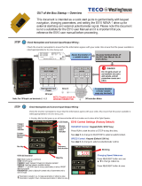
Starting Up the Generator
The following procedure should be followed for starting
up the generator for the first time:
1. The generator output must be disconnected from
the load. Be certain that the main circuit breaker is
open.
2.
Disable the voltage regulator by removing the fuse.
Do not overspeed the generator.
Excessive centrifugal forces could damage the
rotating fields. Be prepared for an emergency
shutdown.
3. Follow the manufacturer’s instructions and start the
prime mover. Check the speed and adjust to the
rpm shown on the generator nameplate.
4. Replace the regulator fuse and adjust the voltage
to the required value (figure 4-2). Check all line to
line and line to neutral voltages to be sure they are
correct and balanced. If the voltages are not
correct, shut down immediately and recheck all
connections. See section 3.
5. Close the main circuit breaker and apply the load.
6. Monitor the generator output current to verify it is at
or below nameplate amps.
7. Adjust engine speed at full load to 1800 rpm for
60 Hz, 1500 rpm for 50 Hz (refer to prime
mover/governor instruction manuals).
8. Before stopping the engine, remove the load by
tripping the main circuit breaker.

11
Section 4 Operation
Voltage Adjustments
The generator output voltage is controlled by the
voltage regulator. There is a cover to access the
control panel on the side of the generator conduit box
(figures 4-1 and 4-2). Refer to the regulator manual for
detailed information. In cases where special or remote
mounted regulators are used, refer to instructions
supplied by the generator set assembler and to the
voltage regulator manual.
Other Adjustments
Depending upon application, adjustments to other
protective and control gear may be required. Refer to
instructions supplied by the generator set manufacturer.
The standard MAGNAPOWER
®
voltage regulator also
has many protective and control circuits built in. Refer
to the regulator manual for further details.
Field Flashing
The standard MAGNAPOWER
®
generator is supplied
with a PMG (permanent magnet generator). It will
never require field flashing.
In rare cases where a special generator may be
furnished without a PMG, refer to the factory for more
detailed information. Include the complete generator
model and serial number (see page 3).
Regulator Access
Standard Marathon Electric Regulator
Figure 4-2
Figure 4-1
See Figure 4-2
for back view
and connections
of this area.

12
Maintenance Section 5
Maintenance – General Information
Dirt, heat, moisture, and vibration are common
enemies of a generator. Keeping the generator clean
and dry, maintaining proper alignment of the generator
and its prime mover, and preventing overloads will
result in efficient operation and long life.
Generators that are outdoors should be protected
from the elements by suitable houses or enclosures.
Dirt and dust will conduct electricity between points of
different electrical potential. Moisture will aggravate
the problem further. Insulation system failure can
result if corrective action is not taken. The condition
of the insulation system can be tested by measuring
insulation resistance (see section 8 - Generator Testing).
Insulation resistance should be checked when putting
the generator into service after it has been in storage
and any time contamination by moisture and dirt
is suspected. Normally, moisture buildup is not a
problem when the generator is running since heat
produced internally will tend to keep it dry. Moisture can
collect in the generator when it is shut down. The
problem will be worse in humid environments or in
areas where extreme temperature changes cause
condensation (dew) to form inside the generator.
Space heaters, air filters, and premium insulation sys-
tems, such as our VPI process, should be considered in
difficult environments.
Accumulations of dust and dirt not only contribute
to insulation breakdown, but they can also increase
temperature by restricting ventilation and by blocking
the dissipation of heat. Some machines are exposed to
accumulations of materials such as talc, lint, rock dust,
or cement dust which may obstruct the ventilation.
The most harmful type of foreign materials include
carbon black, metallic dust and chips, and similar
substances which not only impede the ventilation,
but also form a conductive film over the insulation,
increasing the possibility of insulation failure. Machines
operating in dirty places should be disassembled and
cleaned periodically.
Air Intake and Exhaust
Check the area around the air intake and exhaust
openings to be sure they are clean and unobstructed.
Remove all foreign material and clean all screens
(figure 5-1).
Electrical Connections and Windings
Inspect for loose or contaminated connections. Check
wires for cracked or frayed insulation. Tighten connec-
tions and replace defective or oil-soaked insulation.
If inspection shows that varnish coatings on the
windings have deteriorated, they should be recoated
with insulating varnish. Please refer to Marathon
Electric for insulation system requirements.
Lubrication
All generators are lubricated before leaving the factory
and are ready for operation. As a general rule,
bearings should be relubricated annually or at the
indicated intervals in table 5-3, whichever occurs
first. Unusually severe operating conditions, such as
high ambient or dusty environments, require more
frequent lubrication (every six months or one-half the
table intervals, whichever occurs first).
Use Exxon
®
Polyrex
®
EM or equivalent anti-friction
type, high quality grease with a lubrication temperature
range of -22° to +350°F (-30° to +175°C).
During an overhaul, the grease reservoir should be
thoroughly cleaned and new grease added. The
reservoir should be 1/3 to 1/2 filled with new grease.
Figure 5-1
NOTE: ExxonMobil, Mobil and Polyrex are registered trademarks of Exxon Mobil Corporation or one of its subsidiaries.
Air
Intake
Air
Exhaust

13
Section 5 Maintenance
Be sure to use a grease that is compat-
ible with SRI. Noncompatible lubricants can break
down the grease and cause bearing failure.
Lubrication
To add or renew grease, proceed as follows:
1. Stop unit.
2.
Wipe clean the grease plugs and surrounding parts.
3. Remove fill and drain plugs (figure 5-2).
4. Insert 1/8” N.P.T. grease fitting in fill pipe.
5. Free drain hole of any hard grease, using a piece of
wire if necessary.
6. Using a low pressure grease gun, add grease
according to the amounts in table 5-3.
7. Start unit with drain plug removed – fill pipe may be
open or closed. Allow unit to run 15 minutes to allow
excess grease to drain.
8. Stop unit, wipe off any drained grease, and replace
filler and drain plugs.
Use only clean grease from clean,
closed containers and keep it from being
contaminated while regreasing.
The amount of grease added is very important! Only
enough grease should be added to replace the grease
used by the bearing.
Too much grease can be as harmful as
insufficient grease – use the proper amount.
Frame Bearing Amount of Grease Intervals ¬
Type Size Size Ounces Cubic Inches Teaspoons 60 Hz 50 Hz
Single
1020
326 2.3 4.2 14.0 4000 4800
Bearing
Units
Double
1020
Bearing
1030
326 2.3 4.2 14.0 4000 4800
Units 1040 330 2.3 4.2 14.0 4000 4800
¬ Hours of running time or annually, whichever occurs first.
Figure 5-2
Table 5-3

14
Maintenance Section 5
Electrical components must be dried before placing in
operation if tests indicate that the insulation resistance
is below a safe value (see section 8 – generator testing
for test procedure).
Machines that have been idle for sometime in
unheated and damp locations may have absorbed
moisture. Sudden changes in temperature can cause
condensation or the generator may have become
wet by accident. Windings should be dried out
thoroughly before being put into service. The
following are recommended drying methods.
Space Heaters
Electric space heaters can be installed inside of the
generator. When energized (from a power source
other than the generator), they will heat and dry
the inside of the generator. If an alternate source of
electricity is not available, enclose the generator with a
covering and insert heating units to raise the temperature
15–18°F (8–10°C) above the temperature outside of the
enclosure. Leave a hole at the top of the enclosure to
permit the escape of moisture.
Oven
Place the machine in an oven and bake it at a
temperature not to exceed 194°F (90°C). The voltage
regulator and any electronic component accessories
must be removed from the generator when using
this method.
Forced Air
A portable forced air heater can be used by directing
heat into the air intake (conduit box) and running the
generator with no load and without excitation (this
can be accomplished by removing the regulator fuse).
Heat at point of entry should not exceed 150°F (66°C).
“Short Circuit” Method
The generator can be dried out quickly and thoroughly
by using this method.
Be sure that all of the following
steps are performed and all precautions taken as
personal injury or serious damage to the generator
could result.
1. Disconnect exciter leads F1 and F2 from the
regulator.
2. Connect a battery or other DC power source of
approximately 20–35 volts to the exciter leads F1
and F2. An adjustable voltage source is desirable,
however a rheostat (rated approximately 2 amps)
in series with the DC power source will work.
3. Short circuit the generator output lead wires to each
other (L1 to L2 to L3). If using jumpers, be sure they
are large enough to carry full load amperage.
4. Start the generator and measure the current
through the output leads with a clip-on ammeter.
5. Adjust the voltage source to produce approximately
80% of the rated AC nameplate amps, but in no
case exceed nameplate amps. If an adjustable
source is not available and current is excessive, use
a lower DC source voltage or a larger resistor in
series with the source.
Running time will be determined by the amount
of moisture present in the machine. Insulation
resistance checks should be taken every one to four
hours until a fairly constant value is obtained (see
section 8 – Generator Testing for instructions on
measuring insulation resistance).
6. After the generator is dry and the insulation
resistance is brought up to specifications, remove
the short circuit from the line leads, disconnect the
DC source, and reconnect the F1 and F2 leads at
the regulator. Be sure all connections are tight and
correct before attempting to run the generator.
Drying Electrical Insulation

15
Section 5 Maintenance
When electrical components get dirty, the insulation
must be cleaned. There are a number of acceptable
methods for cleaning the generator, each of which
will necessitate disassembly of the unit. The method
of cleaning will be determined by the kind of dirt and
when the unit must be returned to service. Drying
after cleaning is necessary.
Whenever the generator is disassembled, the windings
should be given a thorough inspection and the insu-
lation cleaned, if necessary. The inspection should
include the connection of the windings, insulation,
and varnish coverage. Check the winding ties and coil
supports. Look for any signs of coil movement or
looseness and repair as required.
An electric motor repair shop in your area can
normally assist with the proper cleaning of the
generator windings. They may also be experienced
in special problems (such as seacoast, marine, oil rig,
mining, etc.) that may be peculiar to a certain area.
Solvents
A solvent is usually required to remove accumulated
soil containing oil or grease.
Only petroleum distillates should be used for cleaning
electrical components.
Petroleum solvents of the safety type with a flash
point greater than 100°F (38°C) are recommended.
Winding varnishes are epoxy or poly-
ester based. A solvent that does not attack these
materials should be used.
Adequate ventilation must be available
to avoid fire, explosion, and health hazards where
solvents are used. Avoid breathing solvent vapors.
Rubber gloves or other suitable protection for the
hands should be used. Wear eye protection.
Apply the solvent with a soft brush or rag. Be careful
not to damage the magnet wire or insulation on
the windings.
Dry components thoroughly with moisture-free, low
pressure compressed air.
Cloth and Compressed Air
Cleaning with a dry cloth may be satisfactory when
components are small, the surfaces are accessible,
and only dry dirt is removed.
Blowing dirt out with compressed air is usually effective
particularly when the dirt has collected in places which
cannot be reached with a cloth. Use clean dry air at
30 psi (206 KPa).
Brushing and Vacuum Cleaning
Dry dust and dirt may be removed by brushing with
bristle brushes followed by vacuum cleaning. Do not
use wire brushes. Vacuum cleaning is an effective and
desirable method of removing dry and loose dirt.
Shell Blasting
Air blasting with ground nut shells may be satisfactory
for removal of hard dirt deposits from insulation. Use
mild abrasives such as 12–20 mesh ground walnut
shells.
Steam Cleaning
If the generator is completely disassembled, including
bearings and electronic components, steam cleaning
of the major parts and windings is very effective.
However, before the generator can be put back into
service, the machine must be thoroughly dried in an
oven to remove all moisture.
Cleaning Methods

16
Service Section 6
Removal from Prime Mover
Be sure all power is off before
servicing. Failure to follow all safety instructions can
result in serious personal injury or death.
Note: Before disconnecting any electrical wiring, be
sure it is marked and can be identified for reinstallation.
Remark as required.
1. Remove conduit box covers (figures 6-1 and 6-2).
2. Disconnect all external wiring from the generator
leads (or bus bars) inside the conduit box.
3.
Remove all conduit or ducting from the conduit
box.
4. Attach a suitable hoist to the generator lifting lugs.
5. a. For single bearing generators, remove the bolts
mounting the screen assembly to the SAE
adapter and remove the screen (figure 6-3).
(Note: Do not remove the dripcover from the
screen assembly if so equipped.) Remove the
capscrews attaching the drive discs to the
flywheel and remove the capscrews attaching
the SAE adapter to the flywheel housing.
b. For two-bearing generators, disconnect the
coupling or sheave and belts between the
generator and prime mover (follow the coupling
manufacturer’s instructions for disconnection).
Do not apply any force to the
generator fan for lifting or rotating the generator
rotor. Disregarding these instructions may cause
personal injury or equipment damage.
6. Remove the mounting bolts which secure the
generator to the base. To make reinstallation easier,
note the position of and save any shims that were
used under the feet for alignment.
7. Raise the generator slightly and move the
generator away from the prime mover. Raise or lower
the generator to take pressure off of the drive discs
so they slide easily out of the flywheel.
8. On single bearing generators, if generator is to be
shipped, see Shipping Instructions (section 10) for
proper rotor support.
Figure 6-1
Figure 6-2
Figure 6-3

Section 6 Service
17
Conduit Box Removal
1. Note the location and markings (remark as
required) and remove connections from voltage
regulator, capacitor, and any other conduit box
mounted control (figures 6-4 and 6-5).
2. On generators equipped with bus bars, mark all
connections and disassemble main stator (power)
leads from the generator side of the bus bars.
3.
Remove bolts holding conduit box in place (figure 6-6).
4. Remove conduit box (figure 6-7).
Figure 6-4
Figure 6-6
Figure 6-7
Figure 6-5

18
Service Section 6
Exciter Stator (Field) Removal
1. Disconnect F1 and F2 leads from the corres-
ponding F1 and F2 terminals on the regulator.
2. Remove all cable ties so the F1 and F2 leads can
be removed with the exciter stator. Remove the four
capscrews and belleville washers holding the
exciter stator in place (figure 6-8). Remove the
exciter stator using a lifting strap or fixture (figure 6-9).
Exciter Armature (Rotor) Removal
1. Note markings and disconnect the main rotor leads
coming out of the aluminum standoff plate lead hole
from the rectifier aluminum angle (figure 6-10).
2. Remove the capscrew and belleville washer which
holds the exciter (rotor) armature to the generator
shaft (figure 6-11).
3. Use a six inch, 7/8-14NF capscrew for a puller (see
section 9). The hole that the mounting bolt goes
through is threaded. Screw the puller bolt into the hole
and it will push against the end of the shaft (figure 6-12).
Carefully feed the main rotor leads through the hole as
the exciter armature is removed (figure 6-13).
Figure 6-8
Figure 6-9
Figure 6-10
Figure 6-11
Figure 6-12
Figure 6-13
/