Page is loading ...

USER MANUAL
EN
No. 50531145 Receiver
Wireless remote control for single- and multi-colored LEDs 12-24 V
LED Strip 4in1 Zone RF Controller
No. 50531140 Set (receiver and remote control)
www.eurolite.de
1
•
EN
Thank you for purchasing this LED control system. The wireless
receiver is especially designed for control of single- and
multi-colored (CW+WW, RGB, RGBW) LED strips requiring an
operating voltage of 12 V and 24 V direct current. The receiver is
operated by wireless control (2.4 GHz) via the remote control. 4
control zones are available. Multiple receivers can be assigned to
the zones as desired and controlled via the same remote control,
either separately or in groups. As the receivers forward the radio
signal, a large range can be covered and all color settings run in
sync. The maximum power consumption of a channel must not
exceed 6 A and of all LEDs connected 24 A. The connection must
be made by skilled personnel only. Please read these operating
instructions carefully before using the product. They contain
important information for the correct use of your product. Please
keep them for future reference.
SAFETY INSTRUCTIONS
•
Only use the product according to the instructions given herein. Damages due to
failure to follow these operating instructions will void the warranty! We do not assume
any liability for any resulting damage.
•
We do not assume any liability for material and personal damage caused by improper
use or non-compliance with the safety instructions. In such cases, the
warranty/guarantee will be null and void.
•
Unauthorized rebuilds or modifications of the product are not permitted for reasons of
safety and render the warranty invalid.
•
This product is not a toy. Keep it out of the reach of children. Do not leave packaging
material lying around carelessly.
•
Keep this device away from rain and moisture. Indoor use only.
•
Protect the product against excessive humidity and heat. The recommended
temperature is -5 to +45°C.
•
Before taking into operation, check upon possible damages. If defective, the product
must not be taken into operation.
•
This product is maintenance-free, except for occasional cleaning. You can use a
slightly dampened cloth for cleaning. Never use alcohol or solvents.
•
Maintenance and service operations are only to be carried out by authorized dealers.

INSTALLATION
2
•
EN
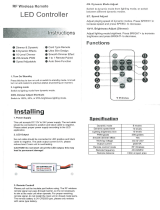
Overview
Setup
•
Install the receiver in a suitable spot and remove the covers from the terminals.
•
Connect the LEDs to the negative and positive OUTPUT terminals (V+ = common positive pole,
V- = see figure on next page). The load by the LEDs must not exceed 6 A per channel. The
overall load must not exceed 24 A to avoid damage to the receiver.
•
For power supply, connect a regulated power supply unit (min. 12 V, max. 24 V) to the negative
and positive INPUT terminals.
•
Use the DIP switches to select the operating mode according to the connected LEDs:
RGB RGBW DIM CCT
•
Screw on the covers with the screws provided.
•
For power supply of the remote control, insert two 1.5 V AAA batteries into the battery
compartment as indicated.
•
For operation the receiver needs to be assigned to the remote control (see chapter “Wireless
Connection” on page 4).
DIP switch to select LED type
Power connection: 12-24V DC
Connectors for LEDs

INSTALLATION
3
•
EN
Application example 1: Single-color LEDs
V+→V+, CH1→V‒, CH2→V‒, CH3→V‒, CH4→V‒
Application example 2: White LEDs (CW+WW) with variable color temperature
V+→V+, CH1→CW, CH2→WW, CH3→CW, CH4→WW
Application example 3: RGB LEDs
V+→V+, CH1→R, CH2→G, CH3→B, CH4→not connected
Application example 4: RGBW LEDs
V+→V+, CH1→R, CH2→G, CH3→B, CH4→W

WIRELESS CONNECTION
4
•
EN
For the remote control to work together with the receiver, the two devices first have to be paired.
There are four separate control zones. Multiple receivers can be assigned to the four zones as
desired and controlled with a mutual remote control. The receivers can be operated in different
modes so it is possible to operate each zone with different LED types. The functions of the
remote control change according to the set operating mode of the respective receiver.
If multiple receivers are used in the same control zone, the receivers exchange signals among
each other. As a result, all dynamic and static color settings run in sync and there is no visible
difference to a wired system.
Please note:
1) The devices are not paired by default. Each remote control has its own code. To avoid
interferences during operation, the devices need to be paired manually during installation.
2) The receiver can be assigned to only one code at a time and needs to be reset to factory
settings before a new code can be assigned.
3) As the receiver has to be switched on for assigning a code, multiple devices can be
configured simultaneously. In this case, we recommend separately switchable sockets for
different areas of the installation so that certain areas can remain switched off during the
configuration process.
remote control (20 meters)
receiver (10 meters)

WIRELESS CONNECTION
5
•
EN
Pairing the remote control with the receiver
When paired, the receiver can be controlled via the remote control.
Step Procedure Remarks
1
Connect the LEDs and switch on the
receiver.
1) If the receiver has been paired before,
it has to be reset to factory settings
before it can be paired again.
2) Provided that they are within the range
of the remote control, multiple
receivers can be configured
simultaneously.
2
Select a control zone.
Select the desired control zone using the
ZONE button on the remote control. The
respective indicator lights.
3
Keep the ON button pressed for 5
seconds to switch to pairing mode. The
RF indicator now flashes rapidly.
The pairing process is automatically
terminated after 60 seconds or by
pressing any button.
4
The connected LEDs flash three times
and then return to their previous state.
The devices have been paired
successfully.
Resetting the receiver
After being reset to factory settings, the receiver can be paired with a new remote control.
Step Procedure Remarks
1
Connect the LEDs and switch on the
receiver.
1) The receiver should be reset within 60
seconds after power on.
2) Provided that they are within the
range of the remote control, multiple
receivers can be configured
simultaneously.
2
Keep the OFF button pressed for 5
seconds to initiate the resetting
process. The RF indicator now flashes
rapidly.
1) It is not necessary to select a certain
control zone.
2) The resetting process is automatically
terminated after 60 seconds or by
pressing any button.
3) Any remote control can be used to
reset the receiver.
3
The connected LEDs flash three times
and then return to their previous state.
The receiver has been reset to factory
settings successfully.

WIRELESS CONNECTION
6
•
EN
Pairing multiple remote controls
Each remote control is delivered with its own code preconfigured. If you use multiple remote
controls, the code of one remote control needs to be copied to the other remote controls for
them to operate in sync successfully.
Step Procedure Remarks
1
Keep the ON button on the master
remote control pressed for 5 seconds to
switch to copying mode. The RF indicator
now flashes rapidly.
The copying process is automatically
terminated after 60 seconds or by
pressing any button.
2
Take the remote control you wish to copy
the code to and keep the M(ODE) button
pressed for 5 seconds. The RF indicator
switches from 100% brightness to 0%
and flashes. The copying mode has been
activated.
The copying process is automatically
terminated after 30 seconds or after the
code has been copied successfully.
3
The RF indicator on the remote control
the code has been copied to flashes
three times.
The code has been successfully copied
to the new remote control. The device
now automatically quits the copying
mode.
Copying the code from receiver to remote control
Codes can also be copied from a receiver to a remote control, e.g. if the previously used remote
control was lost and needs to be replaced.
Step Procedure Remarks
1
Switch off the receiver.
2
Keep the M(ODE) button on the remote
control pressed for 5 seconds. The RF
indicator switches from 100% brightness
to 0% and flashes. The copying mode
has been activated.
The copying process is automatically
terminated after 30 seconds or after the
code has been copied successfully.
3
Switch on the receiver. The RF indicator
on the remote control flashes three times.
The code has been successfully copied
to the new remote control. The device
now automatically quits the copying
mode.
Notes:
1) The distance between receiver and remote control should not exceed 2 meters during this
procedure.
2) During the copying process, all information of the entire system is being transmitted. It is not
necessary to repeat the procedure for different control zones.
Resetting the remote control
The remote control can be reset to factory settings.
Step Procedure Remarks
1
Keep the M(ODE) button pressed for 20
seconds.
The RF indicator is dimmed down and
flashes while the M(ODE) button is
pressed. After releasing the button, the
indicator lights with 100% brightness
again, indicating that the resetting
process has been activated.
2
Confirm with OFF button. The RF
indicator flashes three times.
The remote control has been reset to
factory settings successfully.

OPERATION
7
•
EN
Single-color LEDs
If the DIP switch has been set to the operating mode DIM, the following functions can be
controlled with the remote control. The remote control switches to stand-by mode after 8
seconds of inactivity and can be reactivated by pressing any button.
Button Function
No function
Power on
Power off
Dimmer ring
Adjusting brightness clockwise
Mode selection: flashing, fade
Reduce brightness by 10% (Nightlight function)
Reduce brightness in 5
levels
(10 %, 30 %, 50 %, 70 %, 100 %)
Increase brightness in 5
levels
(10 %, 30 %, 50 %, 70 %, 100 %)
Reduce brightness in 1024
levels
(Keep button pressed to proceed quicker)
Increase brightness in 1024
levels
(Keep button pressed to proceed quicker)
Reduce speed for dynamic programs in 100
levels
(Keep button pressed to proceed quicker)
Increase speed for dynamic programs in 100
levels
(Keep button pressed to proceed quicker)
Select zones 1-
4 (status indicator lights),
keep pressed for 2 seconds to select all zones (all status indicators light)
RF signal indicator
ON
Mode
Brightness + (5 levels)
Brightness + (1024 levels)
Speed +
Zone indicators
SET
OFF
Dimmer ring
Nightlight
Brightness ‒ (5 levels)
Brightness ‒ (1024 levels)
Speed ‒
Zone selection
(keep pressed for 2 seconds
for all zones)

OPERATION
8
•
EN
White LEDs with variable color temperature
If the DIP switch has been set to the operating mode CCT, the following functions can be
controlled with the remote control.
Button Function
No function
Power on
Power off
Color ring
Set color temperature between 100% cold white and 100% warm white
Mode selection: flashing, 2-color flashing, fade, 2-color fade
Reduce brightness by 10% (Nightlight function)
Reduce brightness in 5
levels
(10 %, 30 %, 50 %, 70 %, 100 %)
Increase brightness in 5
levels
(10 %, 30 %, 50 %, 70 %, 100 %)
Reduce brightness in 1024
levels
(Keep button pressed to proceed quicker)
Increase brightness in 1024
levels
(Keep button pressed to proceed quicker)
Reduce speed for dynamic programs in 100
levels
(Keep button pressed to proceed quicker)
Increase speed for dynamic programs in 100
levels
(Keep button pressed to proceed quicker)
Select zones 1-
4 (status indicator lights),
keep pressed for 2 seconds to select all zones (all status indicators light)
RF signal indicator
ON
Mode
Brightness + (5 levels)
Brightness + (1024 levels)
Speed +
Zone indicators
SET
OFF
Color ring
Nightlight
Brightness ‒ (5 levels)
Brightness ‒ (1024 levels)
Speed ‒
Zone selection
(keep pressed for 2 seconds
for all zones)

OPERATION
9
•
EN
RGB LEDs
If the DIP switch has been set to the operating mode RGB, the following functions can be
controlled with the remote control.
Button Function
No function
Power on
Power off
Color ring
Color selection (64 colors available)
Mode selection (8 modes available, see table below)
White light on/off
Select 6 static colors (cyan, purple, yellow, blue, green, red)
Select 6 static colors (red, green, blue, yellow, purple, cyan)
Reduce brightness in 1024 levels (keep button pressed to proceed quicker)
Increase brightness in 1024 levels (keep button pressed to proceed quicker)
Reduce speed for dynamic programs in 100 levels
(Keep button pressed to proceed quicker)
Increase speed for dynamic programs in 100 levels
(Keep button pressed to proceed quicker)
Select zones 1-
4 (status indicator lights),
keep pressed for 2 seconds to select all zones (all status indicators light)
Mode Function Remarks Mode Function Remarks
1 Pulsating white
Speed
adjustable,
brightness not
adjustable
5 7 colors fade
Speed
adjustable,
brightness not
adjustable
2 3 colors change 6 Fade R/G
3 7 colors change 7 Fade R/B
4 3 colors fade 8 Fade G/B
RF signal indicator
ON
Mode
6 basic colors
Brightness + (1024 levels)
Speed +
Zone indicators
SET
OFF
Color ring
White
6 basic colors
Brightness ‒ (1024 levels)
Speed ‒
Zone selection
(keep pressed for 2 seconds
for all zones)

OPERATION
10
•
EN
RGBW LEDs
If the DIP switch has been set to the operating mode RGBW, the following functions can be
controlled with the remote control.
Button Function
No function
Power on
Power off
Color ring
Color selection (64 colors available)
Mode selection (8 modes available, see table below)
White light on/off
Reduce brightness of white light in 1024 levels (keep button pressed to proceed quicker)
Increase brightness of white light in 1024 levels (keep button pressed to proceed quicker)
Reduce brightness of RGB light in 1024 levels (keep button pressed to proceed quicker)
Increase brightness of RGB light in 1024 levels (keep button pressed to proceed quicker)
Reduce speed for dynamic programs in 100 levels
(keep button pressed to proceed quicker)
Increase speed for dynamic programs in 100 levels
(keep button pressed to proceed quicker)
Select zones 1-
4 (status indicator lights),
keep pressed for 2 seconds to select all zones (all status indicators light)
Mode Function Remarks Mode Function Remarks
1 Pulsating white
Speed
adjustable,
brightness not
adjustable
5 7 colors fade
Speed
adjustable,
brightness not
adjustable
2 3 colors change 6 Fade R/G
3 7 colors change 7 Fade R/B
4 3 colors fade 8 Fade G/B
RF signal indicator
RGB on
Mode
White brightness +
RGB brightness +
Speed +
Zone indicators
SET
RGB off
Farbring
White on/off
White brightness ‒
RGB brightness ‒
Speed ‒
Zone selection
(keep pressed for 2 seconds for
all zones

TECHNICAL SPECIFICATIONS
11
•
EN
Remote control
Carrier frequency: 2.4 GHz
Range: ca. 20 m
Battery: 2 x 1,5V AAA LR03 (not included)
Standby current: <18 µA
Operating current: 20 mA
Dimensions (LxWxH): 164 x 45 x 26 mm
Weight: 0.95 g
Receiver
Power supply: 12-24 V DC
Standby current: <1 W
Output power: max. 288 W (12 V), 576 W (24 V)
Load: max. 6 A per channel (24 A overall load)
Protective circuit: Short circuit
PWM frequency: 1000 Hz
Dimensions (LxWxH): 160 x 46 x 25 cm
Weight: 130 g
All information is subject to change without prior notice. © 30.03.2019

PROTECTING THE ENVIRONMENT
Disposal of old equipment
When to be definitively put out of operation, take the product to a local recycling
plant for a disposal which is not harmful to the environment. Devices marked with
this symbol must not be disposed of as household waste. Contact your retailer or
local authorities for more information. Remove any inserted batteries and dispose of
them separately from the product.
You as the end user are required by law (Battery Ordinance) to return all used
batteries/ rechargeable batteries. Disposing of them in the household waste is
prohibited. You may return your used batteries free of charge to collection points in
your municipality and anywhere where batteries/rechargeable batteries are sold. By
disposing of used devices and batteries correctly, you contribute to the protection of
the environment.
Steinigke Showtechnic GmbH • Andreas-Bauer-Str. 5 • 97297 Waldbüttelbrunn, Germany
D00123256 Version 1.0 Publ. 30/03/2019
/