Page is loading ...

WJ200
Series Inverter
Quick Reference Guide
• Single-phase Input 200V class
• Three-phase Input 200V class
• Three-phase Input 400V class
Hitachi Industrial Equipment Systems Co., Ltd.
Manual Number: NT3251AX
March 2012
Refer to the user manual for detail


1
UL® Cautions, Warnings and Instructions xii
Warnings and Cautions for Troubleshooting and Maintenance
(Standard to comply with : UL508C,CSA C22.2 No.14-05)
Warning Markings
GENERAL:
These devices are open type Power Conversion Equipment. They are intended to be used
in an enclosure. Insulated gate bipolar transistor (IGBT) incorporating microprocessor
technology. They are operated from a single or three-phase source of supply, and intended
to control three-phase induction motors by means of a variable frequency output. The units
are intended for general-purpose industrial applications.
MARKING REQUIREMENTS:
Ratings - Industrial control equipment shall be plainly marked with the Listee’s name,
trademark, File number, or other descriptive marking by which the organization responsible
for the product may be identified;
a) “Maximum surrounding air temperature rating of 50 ºC.”
b) “Solid State motor overload protection reacts with max. 150 % of FLA”.
c) “Install device in pollution degree 2 environment.”
d) “Suitable for use on a circuit capable of delivering not more than 100,000 rms
Symmetrical Amperes, 240 or 480 Volts Maximum.”
e) “When Protected by CC, G, J or R Class Fuses.” or “When Protected By A Circuit
Breaker Having An Interrupting Rating Not Less Than 100,000 rms Symmetrical
Amperes, 240 or 480 Volts Maximum.”
f) “Integral solid state short circuit protection does not provide branch circuit protection.
Branch circuit protection must be provided in accordance with the National Electrical
Code and any additional local codes.”

2
Terminal symbols and Screw size
Inverter Model Screw Size
Required
Torque (N-m)
Wire range
WJ200-001S
WJ200-002S
WJ200-004S
M3.5 1.0 AWG16 (1.3mm
2
)
WJ200-007S M4 1.4 AWG12 (3.3mm
2
)
WJ200-015S
WJ200-022S
M4 1.4 AWG10 (5.3mm
2
)
WJ200-001L
WJ200-002L
WJ200-004L
WJ200-007L
M3.5 1.0 AWG16 (1.3mm
2
)
WJ200-015L M4 1.4 AWG14 (2.1mm
2
)
WJ200-022L M4 1.4 AWG12 (3.3mm
2
)
WJ200-037L M4 1.4 AWG10 (5.3mm
2
)
WJ200-055L
WJ200-075L
M5 3.0 AWG6 (13mm
2
)
WJ200-110L M6 3.9 to 5.1 AWG4 (21mm
2
)
WJ200-150L M8 5.9 to 8.8 AWG2 (34mm
2
)
WJ200-004H
WJ200-007H
WJ200-015H
M4 1.4 AWG16 (1.3mm
2
)
WJ200-022H
WJ200-030H
M4 1.4 AWG14 (2.1mm
2
)
WJ200-040H M4 1.4 AWG12 (3.3mm
2
)
WJ200-055H
WJ200-075H
M5 3.0 AWG10 (5.3mm
2
)
WJ200-110H
WJ200-150H
M6 3.9 to 5.1 AWG6 (13mm
2
)

3
Fuse Sizes
Distribution fuse size marking is included in the manual to indicate that the unit shall be
connected with a Listed Cartridge Nonrenewable fuse, rated 600 Vac with the current ratings as
shown in the table below or Type E Combination Motor Controller marking is included in the
manual to indicate that the unit shall be connected with,LS Industrial System Co.,Ltd,Type E
Combination Motor Controller MMS Series with the ratings as shown in the table below:
Inverter Model Type Fuse Rating Type E CMC
WJ200-001S
WJ200-002S
WJ200-004S
10A, AIC 200kA
WJ200-007S 20A, AIC 200kA
WJ200-015S
WJ200-022S
30A, AIC 200kA
MMS-32H,240V,40A
WJ200-001L
WJ200-002L
WJ200-004L
10A, AIC 200kA
WJ200-007L
WJ200-015L
15A, AIC 200kA
WJ200-022L 20A, AIC 200kA
WJ200-037L 30A, AIC 200kA
MMS-32H,240V,40A
WJ200-055L
WJ200-075L
60A, AIC 200kA
WJ200-110L
WJ200-150L
80A, AIC 200kA
MMS-100H,240V,80A
WJ200-004H
WJ200-007H
WJ200-015H
WJ200-022H
10A, AIC 200kA
WJ200-030H
WJ200-040H
15A, AIC 200kA
WJ200-055H
WJ200-075H
30A, AIC 200kA
WJ200-110H
WJ200-150H
Class J
50A, AIC 200kA
MMS-32H,480V,40A
or
MMS-63H,480V,52A

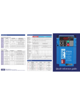
4
Inverter Specification Label
The Hitachi WJ200 inverters have product labels located on the right side of the housing,
as pictured below. Be sure to verify that the specifications on the labels match your power
source, and application safety requirements.
Inverter Specification Label
The model number for a specific inverter contains useful information about its operating
characteristics. Refer to the model number legend below:
WJ200
001 S F
Series name
Configuration type
F=with keypad
Input voltage:
S=Single-phase 200V class
L=Three-phase 200V class
H=Three-phase 400V class
A
pplicable motor capacity in kW
001=0.1kW 037=3.7kW
002=0.2kW 040=4.0kW
004=0.4kW 055=5.5kW
007=0.75kW 075=7.5kW
015=1.5kW 110=11kW
022=2.2kW 150=15kW
030=3.0kW
200-240
200-240
2.0/1.3
1.2
/
1. 0
1005
05A
_
T12345
_
A
_
-001
-001SF
Model name
Input ratings
Output ratings
MFG number
Ver:2.0

5
WJ200 Inverter Specifications
Model-specific tables for 200V and 400V class inverters
The following tables are specific to WJ200 inverters for the 200V and 400V class model
groups. Note that “General Specifications” on page in this chapter
apply to both voltage
class groups. Footnotes for all specification tables follow the table below.
Item Single-phase 200V class Specifications
WJ200 inverters, 200V models 001SF 002SF 004SF 007SF 015SF 022SF
VT 0.2 0.4 0.55 1.1 2.2 3.0 kW
CT 0.1 0.2 0.4 0.75 1.5 2.2
VT
1/4 1/2 3/4 1.5 3 4
Applicable motor size
HP
CT
1/8 1/4 1/2 1 2 3
VT 0.4 0.6 1.2 2.0 3.3 4.1 200V
CT 0.2 0.5 1.0 1.7 2.7 3.8
VT 0.4 0.7 1.4 2.4 3.9 4.9
Rated capacity (kVA)
240V
CT 0.3 0.6 1.2 2.0 3.3 4.5
Rated input voltage
Single-phase: 200V-15% to 240V +10%, 50/60Hz ±5%
Rated output voltage Three-phase: 200 to 240V (proportional to input voltage)
VT 1.2 1.9 3.5 6.0 9.6 12.0 Rated output current (A)
CT 1.0 1.6 3.0 5.0 8.0 11.0
Starting torque 200% at 0.5Hz
Without resistor
100%:
≤
50Hz
50%:
≤
60Hz
70%:
≤
50Hz
50%:
≤
60Hz
20%:
≤
50Hz
20%:
≤
60Hz
Braking
With resistor 150% 100%
DC braking Variable operating frequency, time, and braking force
kg 1.0 1.0 1.1 1.6 1.8 1.8 Weight
lb 2.2 2.2 2.4 3.5 4.0 4.0

6
WJ200 Inverter Specifications, continued…
Item Three-phase 200V class Specifications
WJ200 inverters, 200V models
001LF 002LF 004LF 007LF 015LF 022LF
VT 0.2 0.4 0.75 1.1 2.2 3.0 kW
CT 0.1 0.2 0.4 0.75 1.5 2.2
VT
1/4 1/2 1 1.5 3 4
Applicable motor size
HP
CT
1/8 1/4 1/2 1 2 3
VT 0.4 0.6 1.2 2.0 3.3 4.1 200V
CT 0.2 0.5 1.0 1.7 2.7 3.8
VT 0.4 0.7 1.4 2.4 3.9 4.9
Rated capacity (kVA)
240V
CT 0.3 0.6 1.2 2.0 3.3 4.5
Rated input voltage
Three-phase: 200V-15% to 240V +10%, 50/60Hz ±5%
Rated output voltage Three-phase: 200 to 240V (proportional to input voltage)
VT 1.2 1.9 3.5 6.0 9.6 12.0 Rated output current (A)
CT 1.0 1.6 3.0 5.0 8.0 11.0
Starting torque 200% at 0.5Hz
Without resistor
100%:
≤
50Hz
50%:
≤
60Hz
70%:
≤
50Hz
50%:
≤
60Hz
20%:
≤
50Hz
20%:
≤
60Hz
Braking
With resistor 150% 100%
DC braking Variable operating frequency, time, and braking force
kg 1.0 1.0 1.1 1.2 1.6 1.8 Weight
lb 2.2 2.2 2.4 2.6 3.5 4.0
Item Three-phase 200V class Specifications
WJ200 inverters, 200V models
037LF 055LF 075LF 110LF 150LF
VT 5.5 7.5 11 15 18.5 kW
CT 3.7 5.5 7.5 11 15
VT
7.5 10 15 20 25
Applicable motor size
HP
CT
5 7.5 10 15 20
VT 6.7 10.3 13.8 19.3 20.7 200V
CT 6.0 8.6 11.4 16.2 20.7
VT 8.1 12.4 16.6 23.2 24.9
Rated capacity (kVA)
240V
CT 7.2 10.3 13.7 19.5 24.9
Rated input voltage
Three-phase: 200V-15% to 240V +10%, 50/60Hz ±5%
Rated output voltage Three-phase: 200 to 240V (proportional to input voltage)
VT 19.6 30.0 40.0 56.0 69.0 Rated output current (A)
CT 17.5 25.0 33.0 47.0 60.0
Starting torque 200% at 0.5Hz
Without resistor
20%:
≤
50Hz
20%:
≤
60Hz
Braking
With resistor 100% 80%
DC braking Variable operating frequency, time, and braking force
Kg 2.0 3.3 3.4 5.1 7.4 Weight
lb 4.4 7.3 7.5 11.2 16.3

7
WJ200 Inverter Specifications, continued…
Item Three-phase 400V class Specifications
WJ200 inverters, 400V models
004HF 007HF 015HF 022HF 030HF 040HF
VT 0.75 1.5 2.2 3.0 4.0 5.5 kW
CT 0.4 0.75 1.5 2.2 3.0 4.0
VT 1 2 3 4 5 7.5
Applicable motor size
HP
CT 1/2 1 2 3 4 5
VT 1.3 2.6 3.5 4.5 5.7 7.3 380V
CT 1.1 2.2 3.1 3.6 4.7 6.0
VT 1.7 3.4 4.4 5.7 7.3 9.2
Rated capacity (kVA)
480V
CT 1.4 2.8 3.9 4.5 5.9 7.6
Rated input voltage
Three-phase: 400V-15% to 480V +10%, 50/60Hz ±5%
Rated output voltage Three-phase: 400 to 480V (proportional to input voltage)
VT 2.1 4.1 5.4 6.9 8.8 11.1 Rated output current (A)
CT 1.8 3.4 4.8 5.5 7.2 9.2
Starting torque 200% at 0.5Hz
Without resistor
100%:
≤
50Hz
50%:
≤
60Hz
70%:
≤
50Hz
50%:
≤
60Hz
20%:
≤
50Hz
20%:
≤
60Hz
Braking
With resistor 150%
DC braking Variable operating frequency, time, and braking force
kg 1.5 1.6 1.8 1.9 1.9 2.1 Weight
lb 3.3 3.5 4.0 4.2 4.2 4.6
Item Three-phase 400V class Specifications
WJ200 inverters, 400V models
055HF 075HF 110HF 150HF
VT 7.5 11 15 18.5 kW
CT 5.5 7.5 11 15
VT 10 15 20 25
Applicable motor size
HP
CT 7.5 10 15 20
VT 11.5 15.1 20.4 25.0 380V
CT 9.7 11.8 15.7 20.4
VT 14.5 19.1 25.7 31.5
Rated capacity (kVA)
480V
CT 12.3 14.9 19.9 25.7
Rated input voltage
Three-phase: 400V-15% to 480V +10%, 50/60Hz ±5%
Rated output voltage Three -phase: 400 to 480V (proportional to input voltage)
VT 17.5 23.0 31.0 38.0 Rated output current (A)
CT 14.8 18.0 24.0 31.0
Starting torque 200% at 0.5Hz
Without resistor
20%:
≤
50Hz
20%:
≤
60Hz
Braking
With resistor 150%
DC braking Variable operating frequency, time, and braking force
kg 3.5 3.5 4.7 5.2 Weight
lb 7.7 7.7 10.4 11.5

8
The following table shows which models need derating.
1-ph 200V class Need
derating
3-ph 200V class Need
derating
3-ph 400V class Need
derating
WJ200-001S
-
WJ200-001L
-
WJ200-004H
WJ200-002S
-
WJ200-002L
WJ200-007H
WJ200-004S
WJ200-004L
WJ200-015H
-
WJ200-007S
WJ200-007L
-
WJ200-022H
-
WJ200-015S
-
WJ200-015L
-
WJ200-030H
-
WJ200-022S
-
WJ200-022L
-
WJ200-040H
- -
WJ200-037L
WJ200-055H
-
- -
WJ200-055L
-
WJ200-075H
- -
WJ200-075L
WJ200-110H
- -
WJ200-110L
WJ200-150H
- -
WJ200-150L
- -
:need derating
-:need no derating
Use the following derating curves to help determine the optimal carrier frequency setting
for your inverter and find the output current derating. Be sure to use the proper curve for
your particular WJ200 inverter model number.

9
Basic System Description
A motor control system will obviously include a motor and inverter, as well as a circuit
breaker or fuses for safety. If you are connecting a motor to the inverter on a test bench
just to get started, that’s all you may need for now. But a system can also have a variety of
additional components. Some can be for noise suppression, while others may enhance the
inverter’s braking performance. The figure and table below show a system with all the
optional components you might need in your finished application.
Name Function
Breaker /
disconnect
A molded-case circuit breaker (MCCB), ground fault
interrupter (GFI), or a fused disconnect device. NOTE: The
installer must refer to the NEC and local codes to ensure
safety and compliance.
Input-side
AC Reactor
This is useful in suppressing harmonics induced on the
power supply lines and for improving the power factor.
WARNING: Some applications must use an input-side AC
Reactor to prevent inverter damage. See Warning on next
page.
Radio noise filter
Electrical noise interference may occur on nearby
equipment such as a radio receiver. This magnetic choke
filter helps reduce radiated noise (can also be used on
output).
EMC filter (for
CE applications,
see Appendix D)
Reduces the conducted noise on the power supply wiring
between the inverter and the power distribution system.
Connect to the inverter primary (input) side.
Radio noise filter
(use in non-CE
applications)
This capacitive filter reduces radiated noise from the main
power wires in the inverter input side.
DC link choke
Suppress harmonics generated by the inverter. However, it
will not protect the input diode bridge rectifier.
Radio noise filter
Electrical noise interference may occur on nearby
equipment such as a radio receiver. This magnetic choke
filter helps reduce radiated noise (can also be used on
input).
Output-side
AC Reactor
This reactor reduces the vibration in the motor caused by
the inverter’s switching waveforms, by smoothing the
waveform to approximate commercial power quality. It is
also useful to reduce harmonics when wiring from the
inverter to the motor is more than 10m in length.
LCR filter
Sine wave shaping filter for output side.
Breaker,
MCCB or
GFI
From power supply
M
Thermal
switch
L1 L2 L3
T1 T2 T3
Inverter
+1
+
GND

10
Determining Wire and Fuse Sizes
The maximum motor currents in your application determines the recommended wore size.
The following table gives the wire size in AWG. The “Power Lines” column applies to the
inverter input power, output wires to the motor, the earth ground connection, and any other
components shown in the “Basic System Description” on page 9. The “Signal Lines”
column applies to any wire connecting to the two green connectors just inside the front
cover panel.
Motor Output Wiring
Applicable
equipment
kW HP
VT CT VT CT
Inverter Model
Power Lines Signal Lines
Fuse (UL-rated,
class J, 600V ,
Maximum
allowable current)
0.2 0.1 ¼ 1/8
WJ200-001SF
0.4 0.2 ½ ¼
WJ200-002SF
0.55
0.4 ¾ ½
WJ200-004SF
AWG16 / 1.3mm
2
(75°C only)
10A
1.1
0.75
1.5 1
WJ200-007SF
AWG12 / 3.3mm
2
(75°C only)
20A
2.2 1.5 3 2
WJ200-015SF
3.0 2.2 4 3
WJ200-022SF
AWG10 / 5.3mm
2
30A
0.2 0.1 ¼ 1/8
WJ200-001LF
0.4 0.2 ½ ¼
WJ200-002LF
0.75
0.4 1 ½
WJ200-004LF
10A
1.1
0.75
1.5 1
WJ200-007LF
AWG16 / 1.3mm
2
2.2 1.5 3 2
WJ200-015LF
AWG14 / 2.1mm
2
(75°C only)
15A
3.0 2.2 4 3
WJ200-022LF
AWG12 / 3.3mm
2
(75°C only)
20A
5.5 3.7 7.5 5
WJ200-037LF
AWG10 / 5.3mm
2
(75°C only)
30A
7.5 5.5 10 7.5
WJ200-055LF
11 7.5 15 10
WJ200-075LF
AWG6 / 13mm
2
(75°C only)
60A
15 11 20 15
WJ200-110LF
AWG4 / 21mm
2
(75°C only)
80A
18.5
15 25 20
WJ200-150LF
AWG2 / 34mm
2
(75°C only)
80A
0.75
0.4 1 ½
WJ200-004HF
1.5
0.75
2 1
WJ200-007HF
2.2 1.5 3 2
WJ200-015HF
AWG16 / 1.3mm
2
3.0 2.2 4 3
WJ200-022HF
10A
4.0 3.0 5 4
WJ200-030HF
AWG14 / 2.1mm
2
5.5 4.0 7.5 5
WJ200-040HF
AWG12 / 3.3mm
2
(75°C only)
15A
7.5 5.5 10 7.5
WJ200-055HF
11 7.5 15 10
WJ200-075HF
AWG10/ 5.3mm
2
(75°C only)
30A
15 11 20 15
WJ200-110HF
AWG6 / 13mm
2
(75°C only)
50A
18.5
15 25 20
WJ200-150HF
AWG6 / 13mm
2
(75°C only)
18 to 28
AWG / 0.14
to 0.75 mm
2
shielded wire
(see Note 4)
50A
Note 1: Field wiring must be made by a UL-Listed and CSA-certified closed-loop terminal
connector sized for the wire gauge involved. Connector must be fixed by using
the crimping tool specified by the connector manufacturer.
Note 2: Be sure to consider the capacity of the circuit breaker to be used.
Note 3: Be sure to use a larger wire gauge if power line length exceeds 66ft. (20m).
Note 4: Use 18 AWG / 0.75mm
2
wire for the alarm signal wire ([AL0], [AL1], [AL2]
terminals).

11
Wire the Inverter Input to a Supply
In this step, you will connect wiring to the input of the inverter. First, you must determine
whether the inverter model you have required three-phase power only, or single-phase
power only. All models have the same power connection terminals [R/L1], [S/L2], and
[T/L3]. So you must refer to the specifications label (on the side of the inverter) for
the acceptable power source types! For inverters that can accept single-phase
power and are connected that way, terminal [S/L2] will remain unconnected.
Note the use of ring lug connectors for a secure connection.
Single-phase 200V 0.1 to 0.4kW
Three-phase 200V 0.1 to 0.75kW
Single-phase 200V 0.75 to 2.2kW
Three-phase 200V 1.5, 2.2kW
Three-phase 400V 0.4 to 3.0kW
Chassis Ground (M4)
L1
Power input Output to Motor
N
U/T1
V/T2
W/T3
RB
+1
+
-
Single-phase Three-phase
R/L1
Power input Output to Motor
S/L2
T/L3 U/T1 V/T2 W/T3
RB
PD/+1
P/+ N/
-
Chassis Ground (M4)
L1
Power input Output to Motor
N
U/T1
V/T2
W/T3
RB
+1
+
-
Single-phase Three-phase
R/L1
Power input Output to Motor
S/L2
T/L3 U/T1 V/T2 W/T3
RB
PD/+1
P/+ N/
-

12
Three-phase 200V 3.7kW
Three-phase 400V 4.0kW
Three-phase 200V 5.5, 7.5kW
Three-phase 400V 5.5, 7.5kW
W/T3 V/T2 U/T1
T/L3
S/L2
R/L1
N/
-
P/+
PD/+1
RB
Power input Output to Motor
Chassis Ground (M4)
G G RB
N/
-
P/+
PD/+1
W/T3 V/T2 U/T1
T/L3
S/L2
R/L1
Power input Output to Motor

13
Three-phase 200V 11kW
Three-phase 400V 11, 15kW
Three-phase 200V 15kW
NOTE: An inverter powered by a portable power generator may receive a distorted power
waveform, overheating the generator. In general, the generator capacity should be five
times that of the inverter (kVA).
G G RB
N/
-
P/+
PD/+1
W/T3 V/T2 U/T1
T/L3
S/L2
R/L1
Power input Output to Motor
G G RB
N/
-
P/+
PD/+1
W/T3 V/T2 U/T1
T/L3
S/L2
R/L1
Power input Output to Motor

14
Using the Front Panel Keypad
Please take a moment to familiarize yourself with the keypad layout shown in the figure
below. The display is used in programming the inverter’s parameters, as well as monitoring
specific parameter values during operation.
Key and Indicator Legend
Items Contents
(1) POWER LED Turns ON (Green) while the inverter is powered up.
(2) ALARM LED Turns ON (Red) when the inverter trips.
(3) Program LED
Turns ON (Green) when the display shows changeable parameter.
Blinks when there is a mismatch in setting.
(4) RUN LED Turns ON (Green) when the inverter is driving the motor.
(5) Monitor LED [Hz] Turns ON (Green) when the displayed data is frequency related.
(6) Monitor LED [A] Turns ON (Green) when the displayed data is current related.
(7) Run command LED Turns ON (Green) when a Run command is set to the operator. (Run key is effective.)
(8) 7-seg LED Shows each parameter, monitors etc.
(9) RUN key Makes inverter run.
(10) STOP/RESET key
Makes inverter decelerates to a stop.
Reset the inverter when it is in trip situation
(11) ESC key
Go to the top of next function group, when a function mode is shown
Cancel the setting and return to the function code, when a data is shown
Moves the cursor to a digit left, when it is in digit-to-digit setting mode
Pressing for 1 second leads to display data of d001, regardless of current display.
(12) Up key
(13) Down key
Increase or decrease the data.
Pressing the both keys at the same time gives you the digit-to-digit edit.
(14) SET key
Go to the data display mode when a function code is shown
Stores the data and go back to show the function code, when data is shown.
Moves the cursor to a digit right, when it is in digit-to-digit display mode
(15) USB connector Connect USB connector (mini-B) for using PC communication
(16) RJ45 connector Connect RJ45 jack for remote operator
1
2
RUN
ESC
STOP
RESET
SET
8888
RUN
Hz
A
PWR
ALM
PRG
(1) POWER LED
(2) ALARM LED
(8) 7-seg LED
(4) RUN LED
(10) STOP/RESET key
(15) USB connector
(3) Program LED
(16) RJ45 connector
(14) SET key
(13) Down key (12) Up key
(11) ESC key
(9) RUN key
(7) Run command LED
(5) Monitor LED [Hz]
(6) Monitor LED [A]

15
Keys, Modes, and Parameters
The purpose of the keypad is to provide a way to
change modes and parameters. The term function
applies to both monitoring modes and parameters.
These are all accessible through function codes that are
primary 4-character codes. The various functions are
separated into related groups identifiable by the
left-most character, as the table shows.
Function
Group
Type (Category) of Function Mode to Access
PRG LED
Indicator
“d” Monitoring functions Monitor
“F” Main profile parameters
Program
“A” Standard functions
Program
“b” Fine tuning functions
Program
“C” Intelligent terminal functions
Program
“H” Motor constant related functions
Program
“P” Pulse train input, torque, EzSQ, and
communication related functions
Program
“U” User selected parameters
Program
“E” Error codes
− −
You can see from the following page how to monitor and/or program the parameters.
Keypad Navigation Map
The WJ200 Series inverter drives have many programmable functions and parameters.
Chapter 3 will cover these in detail, but you need to access just a few items to perform the
powerup test. The menu structure makes use of function codes and parameter codes to
allow programming and monitoring with only a 4-digit display and keys and LEDs. So, it is
important to become familiar with the basic navigation map of parameters and functions in
the diagram below. You may later use this map as a reference.
8888
RUN
RUN
ESC
SET
STOP
RESET
1
2
PWR
Hz
ALM
PGM
A

16
NOTE: Pressing the [ESC] key will make the display go to the top of next function group,
regardless the display contents. (e.g. A021 [ESC] b001)
U
V
Press the both up and down key at the same
time in func. code or data display, then
single-digit edit mode will be enabled.
Refer to 2-34 for further information.
d001
V U
ESC
SET
Group "d"
Func. code display
0.00
d002
d104
F001
V U
Group "F"
Func. code display
F002
F004
50.00
50.01
SET
SET
ESC
SET
ESC
Save
A001
V U
Group "A"
Func. code display
A002
A165
00
01
SET
SET
ESC
SET
ESC
Data display
When data is changed, the display
starts blinking, which means that
new data has not been activated yet.
: Saves the data in EEPROM and
returns to func. code display.
: Cancels the data change and
returns to func. code display.
SET
ESC
Group "b"
b001
ESC
Func. code display
: Jumps to the next group
ESC
Func. code display
: Moves to data display
SET
ESC
ESC
Data display (F001 to F003)
Data does not blink because of real time synchronizing
: Saves the data in EEPROM
and returns to func. code display.
: Returns to func. code display without saving data.
SET
ESC

17
[Setting example]
After power ON, changing from 0.00 display to change the A002 (Run command source)
data.
Function code dxxx are for monitor and not possible to change.
Function codes Fxxx other than F004 are reflected on the performance just after changing the data
(before pressing SET key), and there will be no blinking.
A001
A002 02
Display is solid lighting.
01
F001
d001
0.00
Data of d001 will be shown on the
display after the first power ON
Press [ESC] key to show
the function code
Press [ESC] key to move
on to the function group F001
Press [ESC] key Once to move
on to the function group A001.
Press Up key to change increase
function code (A001
A002)
Press SET key to display the data of A002
Press SET key to set
and save the data
When data is changed, the display
starts blinking, which means that new
data has not been activated yet.
ESC
U
V
SET
ESC
ESC
SET
ESC
U
V
:Fix and stores the data and moves back to the function code
:Cancels the change and moves back to the function code
SET
ESC
SET
Press up key to increase the
data (02 01)

18
When a function code is shown… When a data is shown…
ESC key Move on to the next function group
Cancels the change and moves back to the
function code
SET key Move on to the data display
Fix and stores the data and moves back to
the function code
U key
Increase function code Increase data value
V key
Decrease function code Decrease data value
Note
Keep pressing for more than 1 second leads to d001 display, regardless the display situation. But note that
the display will circulates while keep pressing the [ESC] key because of the original function of the key.
(e.g. F001 A001 b001 C001 … displays 50.00 after 1 second)
/