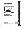
HHB comm HHB MDP500 User manual
- Category
- CD players
- Type
- User manual

OPERATING
INSTRUCTIONS
La versión en español del manual de operaciones la encontrará en la web de HHB – www.hhb.co.uk
La version Française de ce manuel d’utilisation est disponible sur le site web de HHB à www.hhb.co.uk
Eine deutsche Version dieser Bedienungsanleitung ist im Internet unter der Adresse www.hhb.co.uk erhältlich.
HHB MDP500 PORTABLE MINIDISC RECORDER
PDISC_OP.QXD 6/11/00 12:43 pm Page 2
interstage
Phistersvej 31, 2900 Hellerup, Danmark
Telefon 3946 0000, fax 3946 0040
www.interstage.dk
- pro audio with a smile

2
PDISC_OP.QXD 6/11/00 12:43 pm Page 3

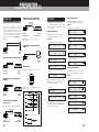
INTRODUCTION . . . . . . . . . . . . . . . . . . . . . . . . . . . 4
Main Features . . . . . . . . . . . . . . . . . . . . . . . . . . . . . 4
PRECAUTIONS . . . . . . . . . . . . . . . . . . . . . . . . . . . 5
SERVICE . . . . . . . . . . . . . . . . . . . . . . . . . . . . . . . . 5
TOP PANEL . . . . . . . . . . . . . . . . . . . . . . . . . . . . . . 6
FRONT PANEL . . . . . . . . . . . . . . . . . . . . . . . . . . . . 7
SIDE PANELS . . . . . . . . . . . . . . . . . . . . . . . . . . . . 8
LCD DISPLAY . . . . . . . . . . . . . . . . . . . . . . . . . . . . 9
NOTATION GUIDE . . . . . . . . . . . . . . . . . . . . . . . . . 9
PREPARATION . . . . . . . . . . . . . . . . . . . . . . . . 10-14
Power Supply . . . . . . . . . . . . . . . . . . . . . . . . . . . . 10
AC Adaptor
Nickel Metal Hydride Rechargeable Batteries
Alkaline Batteries
Power Management
Battery Life Indicator
Date & Time . . . . . . . . . . . . . . . . . . . . . . . . . . 10-11
Date and Time Setting
Date and Time Confirmation
Time Stamp Data Confirmation
Initialising . . . . . . . . . . . . . . . . . . . . . . . . . . . . . . . 11
Initialising Procedure
Factory Default Settings
Connections . . . . . . . . . . . . . . . . . . . . . . . . . . . . . 12
Connecting Microphones to the XLR Input
Analog Source Recording via the XLR Input
Sending Analog Audio to External Analog Equipment
Connecting to Digital Equipment via Coaxial or Optical
Sending Digital Audio to External Digital Equipment via
Coaxial or Optical Outputs
Connecting With a Computer via the USB Interface
Remote Control
LCD Display . . . . . . . . . . . . . . . . . . . . . . . . . . . 13-14
Display During Stop Mode
Display During Play Mode
Display During Record Mode
Display Back Light
Display Contrast
RECORDING . . . . . . . . . . . . . . . . . . . . . . . . . . 15-19
Recording From a Microphone . . . . . . . . . . . . . . . . 15
Mic Attenuation Mode
Basscut Mode
Limiter Mode
Phantom Mode
Recording From Line Sources . . . . . . . . . . . . . . . . . 16
Recording From Digital Sources . . . . . . . . . . . . . . . . 16
Recording From Mono Internal Mic . . . . . . . . . . . . . 16
Basic Recording . . . . . . . . . . . . . . . . . . . . . . . . 16-17
Mono Recording
Setup Menu . . . . . . . . . . . . . . . . . . . . . . . . . . . . . 17
One Touch Setup
How To Save
How To Open
Useful Recording Functions . . . . . . . . . . . . . . . . 17-18
6 Seconds Pre-Recording
Input Monitor Function
Peak Hold Meter
Overwrite Mode
Threshold Level Functions . . . . . . . . . . . . . . . . . 18-19
Record Threshold Level Setting
Auto Increment Function
Auto-Start/Cut Recording Function
Silence Trim
PLAYBACK . . . . . . . . . . . . . . . . . . . . . . . . . . . . . 20
Normal Playback . . . . . . . . . . . . . . . . . . . . . . . . . . 20
Fast Search Function
Direct Track Select Function
Repeat Functions . . . . . . . . . . . . . . . . . . . . . . . . . . 20
Repeat One or Repeat All Function
Repeat A-B
Auto Pause Mode . . . . . . . . . . . . . . . . . . . . . . . . . 20
EDITING . . . . . . . . . . . . . . . . . . . . . . . . . . . . . 21-23
Erase Function . . . . . . . . . . . . . . . . . . . . . . . . . . . 21
Erase Only One Track
Erase All the Tracks At Once
Erase Part of a Track
Divide Function . . . . . . . . . . . . . . . . . . . . . . . . . 21-22
Combine Function . . . . . . . . . . . . . . . . . . . . . . . . . 22
Move Function . . . . . . . . . . . . . . . . . . . . . . . . . 22-23
Disc & Track Naming . . . . . . . . . . . . . . . . . . . . . . . 23
OTHER FUNCTIONS . . . . . . . . . . . . . . . . . . . . . . . 24
Headphone Monitor . . . . . . . . . . . . . . . . . . . . . . . . 24
Digital Output . . . . . . . . . . . . . . . . . . . . . . . . . . . . 24
Key Hold . . . . . . . . . . . . . . . . . . . . . . . . . . . . . . . 24
Copy Protection . . . . . . . . . . . . . . . . . . . . . . . . . . . 24
USB INSTALLATION . . . . . . . . . . . . . . . . . . . . . . . 25
Windows 98 / Windows 2000 Users . . . . . . . . . . . 25
Mac Users (OS 9) . . . . . . . . . . . . . . . . . . . . . . . . . 25
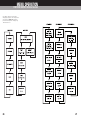
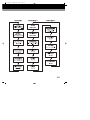
MENU OPERATION . . . . . . . . . . . . . . . . . . . . . 26-27
DISPLAY MESSAGES . . . . . . . . . . . . . . . . . . . . . . 28
TROUBLESHOOTING . . . . . . . . . . . . . . . . . . . . . . 28
MD SYSTEM INFORMATION . . . . . . . . . . . . . . . . 29
TECHNICAL DATA . . . . . . . . . . . . . . . . . . . . . . . . 31
3
CONTENTS
PORTADISC MDP500 MiniDisc Recorder
PDISC_OP.QXD 6/11/00 12:43 pm Page 4

• Versatile analog and digital in/out:
Analog XLR balanced mic/line input,
2 channels
RCA phono unbalanced line
output, 2 channels
Digital in (SPDIF) Coaxial
Optical
Digital out (SPDIF) Coaxial (ON or OFF switchable)
Optical (ON or OFF switchable)
• Imports and exports audio data with a Macintosh or
Windows PC via a Universal Serial Bus (USB)
interface.
• The PORTADISC caters for professional
microphones and is also equipped with a back-up
internal mono microphone. Features include
phantom power (+48V), attenuator, limiter, ganged
limiter, AGC and high-pass filter (bass cut).
• Conforms to the MD standard (Adaptive TRansform
Acoustic Coding – ATRAC version 4.5) in addition to
having a wide variety of MD recording functions:
auto start/cut, auto pause, time stamp and
6-second pre record buffer.
• Five user set-up menus are available for storing
input and system settings.
• Headphone monitor functions include Stereo, Mono
L, Mono R and Mono Both.
• The PORTADISC has a built-in sample rate converter
that automatically converts sample frequencies
from 32kHz to 48kHz into the MD standard
44.1kHz.
• The editing facility offers editing options such as
Divide, Combine, Move and Erase in addition to
naming program titles and discs.
• The PORTADISC features 3-way power source
and power management, with external 12-14V DC,
8 x AA alkaline batteries or 8 x Nickel Metal
Hydride (NiMH) rechargeable batteries (supplied).
The supplied batteries are high capacity 1550mAh
NiMH cells, for optimum performance.
• Switchable auto power down function.
• You may recharge the supplied NiMH batteries in
the PORTADISC with the AC adaptor provided.
• Two recording modes: 80 minutes in stereo mode
or 160 minutes in mono mode.
• Automatic disc loading mechanism.
• Level margin display and peak hold level display.
• Date and time display.
• Parallel remote function.
• LCD display with back light.
• Internal monitor speaker.
• Internal mono microphone suitable for use when
identing tracks, etc.
Thank you for purchasing the HHB PORTADISC MDP500. This manual explains in detail how to use the MD
recorder and also contains important advice on how to use it efficiently and safely. We recommend that you
read this manual first before you start using the PORTADISC. We also recommend that you keep this manual
in a safe place for easy access in the future.
4
INTRODUCTION
PORTADISC MDP500 MiniDisc Recorder
MAIN FEATURES
PDISC_OP.QXD 6/11/00 12:43 pm Page 5

Should the HHB PORTADISC require service, it must be
taken or sent to an HHB authorised dealer. Please
retain the original packing for possible future use, and
ensure the unit is suitably protected during transit. The
manufacturer cannot accept responsibility for damage
caused during transportation. In order to register
ownership it is essential that you complete and return
the user registration card supplied with this product.
All components used in the HHB PORTADISC are
guaranteed against faulty materials or workmanship for a
period of one year from the date of purchase. This
warranty will become void if the product has been
misused, modified or tampered with in any way. HHB
shall not be liable for any consequential or incidental
damages due to the failure of this product. In the unlikely
event of a product failure please contact your local dealer.
Please record the following details:
Serial number: . . . . . . . . . . . . . . . . . . . . . . . . . . . . . . . . . . . . . . . . . . . . . . . . . . . . . . . . . . . . . . . . . . . .
Date purchased: . . . . . . . . . . . . . . . . . . . . . . . . . . . . . . . . . . . . . . . . . . . . . . . . . . . . . . . . . . . . . . . . . .
Dealer: . . . . . . . . . . . . . . . . . . . . . . . . . . . . . . . . . . . . . . . . . . . . . . . . . . . . . . . . . . . . . . . . . . . . . . . . .
The HHB PORTADISC is simple to use but, like all
electrical equipment, care must be taken to ensure
reliable, safe operation. The following points should
always be observed in order to reduce the risk of fire
or electric shocks:
• Do not expose the recorder to extreme conditions of
smoke, water, moisture or excessive vibration.
• Do not insert objects (other than MD discs or
batteries) or liquids into the recorder.
• Do not remove the PORTADISC’s covers (except the
battery compartment). This recorder employs a laser
and there are no user-serviceable parts inside.
• Do not apply pressure or mount heavy objects on the
recorder.
• Do not drop or apply extreme physical shock to the
recorder.
• Disconnect the AC adaptor and remove the batteries
when cleaning.
• Use only specified batteries, the AC adaptor and
connection cables.
• Turn off the power before connecting the AC adaptor
or replacing the batteries.
Please seek qualified service personnel advice if the
PORTADISC appears to be operating abnormally. Power
down the PORTADISC, disconnect the AC adaptor and
remove the batteries if you notice any of the following:
• Unusual mechanical noises from the recorder.
• Liquid has been spilled into the recorder.
• The recorder has been dropped or the casing
damaged in any way.
5
PRECAUTIONS
PORTADISC MDP500 MiniDisc Recorder
SERVICE
PORTADISC MDP500 MiniDisc Recorder
PDISC_OP.QXD 6/11/00 12:43 pm Page 6

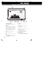
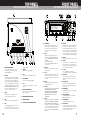
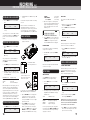
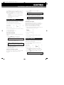
1 BATTERY COMPARTMENT
This cover slides off (from right to left in this
view) and underneath is the battery caddy,
holding 8 x AA batteries.
2 KEYHOLD
Use this button to avoid any accidental operation
during recording. Each time you press the button
for more than two seconds, the hold function
changes from ‘Key Hold ON’ to ‘Key Hold OFF’ and
vice versa. The following buttons can still operate
even when the keyhold function is on: KEY HOLD,
LIGHT, MARK, DISPLAY and POWER. The remote
control connection will not be affected by this
function; i.e., it is always enabled.
3 OPEN
Press this button to eject the MD disc. This
function is disabled during recording.
4 EDIT
Use this button to enter the different edit modes.
5 AMS
Use the button to move back one or more
tracks and the button to move forward one
or more tracks. These buttons are also used in
editing and naming.
6 REWIND
Rewinds the track during playback.
7 PLAY
Use this button to start playing back the track.
8 FAST FORWARD
Fast forwards the track during playback.
9 STOP
Use this button to stop the playback or recording
operation.
10 RECORD VOLUME CONTROL
Dual concentric control for independent left and
right level adjustment.
11 INTERNAL MONO MICROPHONE
12 MONITOR SPEAKER
13 SHOULDER STRAP ATTACHMENT POINTS
6
TOP PANEL
PORTADISC MDP500 MiniDisc Recorder
▲
▲
❙
▲
▲
❙
PDISC_OP.QXD 6/11/00 12:43 pm Page 7

1 BATTERY COMPARTMENT
This cover slides off (from right to left in this
view) and underneath is the battery caddy,
holding 8 x AA batteries.
2 KEYHOLD
Use this button to avoid any accidental operation
during recording. Each time you press the button
for more than two seconds, the hold function
changes from ‘Key Hold ON’ to ‘Key Hold OFF’ and
vice versa. The following buttons can still operate
even when the keyhold function is on: KEY HOLD,
LIGHT, MARK, DISPLAY and POWER. The remote
control connection will not be affected by this
function; i.e., it is always enabled.
3 OPEN
Press this button to eject the MD disc. This
function is disabled during recording.
4 EDIT
Use this button to enter the different edit modes.
5 AMS
Use the button to move back one or more
tracks and the button to move forward one
or more tracks. These buttons are also used in
editing and naming.
6 REWIND
Rewinds the track during playback.
7 PLAY
Use this button to start playing back the track.
8 FAST FORWARD
Fast forwards the track during playback.
9 STOP
Use this button to stop the playback or recording
operation.
10 RECORD VOLUME CONTROL
Dual concentric control for independent left and
right level adjustment.
11 INTERNAL MONO MICROPHONE
12 MONITOR SPEAKER
13 SHOULDER STRAP ATTACHMENT POINTS
7
6
TOP PANEL
PORTADISC MDP500 MiniDisc Recorder
FRONT PANEL
PORTADISC MDP500 MiniDisc Recorder
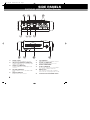
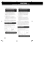
14 PHONE LEVEL
Adjusts the volume level for the headphones and
monitor speaker. The control will pop out if you
press it. The monitor speaker will not function
during recording or when the headphones are
connected.
15 INPUT
Changes the following input related settings:
• Input source: MIC, LINE, DIGITAL, INT MIC, OFF
• Options for MIC: MIC-Att, BASSCUT, LIMITER,
PHANTOM
• Options for LINE: LIMITER
• Options for DIGITAL: COAXIAL, OPTICAL, USB
input connections
16 DISPLAY
Changes the display menu through disc time, level
margin, time & date.
17 LIGHT
Illuminates the display back light for a few seconds.
Hold it down for more than two seconds in order
for it to be continuously lit. Press it again to switch
off the light.
18 MARK
Marks the track number manually during record
mode and play/pause mode.
19 SYSTEM
Changes the following system settings: REC MODE,
TRACK-INCREMENT, THRESHOLD LEVEL,
AUTO-START/CUT, AUTO-PAUSE, PRE-RECORD,
HEADPHONE MONITOR, OVERWRITE MODE,
REPEAT MODE, DIGITAL OUTPUT and AUTO
POWER DOWN.
20 SETUP
Changes the following setup options: OPEN SETUP,
SAVE SETUP, CLOCK/DATE SETUP, DATE FORMAT,
PEAK HOLD METER and DISPLAY CONTRAST. Use
this button to save and recall set-ups. OPEN SETUP
consists of five user set-ups, which can be used to
store all the menu settings on the recorder, and
three recording presets – MIC REC, LINE REC and
DIGI REC.
21 REC LEVEL
Adjusts the analog recording level manually for mic
and line inputs. This control does not affect the
signal level when the AGC function is set to ‘ON’.
The outer control adjusts the left hand channel and
the inner control adjusts the right hand channel. A
friction lock between the two controls allows them
to move together but also be adjusted individually.
22 RECORD
Slide this button to the right to enter record mode.
23 POWER
Press this button for one second to power ON and
press for more than one second then release to
power OFF. This button does not turn the power off
during recording and TOC operations.
24 F1, F2, F3
Selects the parameters according to the
corresponding set-up functions on the display above.
25 LCD DISPLAY
Shows level metering, disc information, timing
information and all the menu select and control
displays.
26 REC LEVEL LOCK
Mechanically locks the REC LEVEL knob position in
order to avoid accidental adjustment. Slide this
button up to lock.
27 REC INDICATOR
This LED will light up red in record mode and blink
in record pause mode.
28 BAT CHG INDICATOR
This LED will light up green when charging the
NiMH rechargeable batteries.
29 PAUSE INDICATOR
This LED will light up yellow in pause mode.
30 PAUSE BUTTON
Use this button to pause the record or playback
operation. Pressing this button before pressing the
record button will put the recorder into record
pause mode, ready for recording.
s
s
y
s
s
y

8
SIDE PANELS
PORTADISC MDP500 MiniDisc Recorder
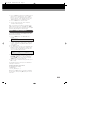
31 PHONES SOCKET
1/4" jack socket for headphone connection.
32 LINE OUT LEFT AND RIGHT CONNECTORS
(Unbalanced RCA phono.) To send analog output
signals to other equipment.
33 COAXIAL I/O CONNECTORS
(Unbalanced RCA phono.) SPDIF digital coaxial
connectors.
34 MIC/LINE CONNECTORS
(Balanced XLR.) To connect either MIC or LINE
inputs.
35 REMOTE CONNECTOR
Parallel remote control connector.
36 USB CONNECTOR
USB interface port for a compatible computer.
37 OPTICAL I/O CONNECTORS
(TOSlink.) SPDIF digital optical connectors.
38 BATTERY COMPARTMENT
39 DC INPUT CONNECTOR
To connect the standard accessory AC adaptor,
or an optional car adaptor. DC12-14V.
40 MINIDISC SLOT
A disc must be inserted into this slot with the
arrow on the disc casing facing into the recorder.
41 SHOULDER STRAP ATTACHMENT POINTS
PDISC_OP.QXD 6/11/00 12:43 pm Page 9

9
LCD DISPLAY
PORTADISC MDP500 MiniDisc Recorder
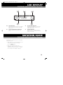
42-3 LEVEL INDICATOR
The bar meter shows the audio level in playback
and record. (42) left hand channel (43) right
hand channel.
44 RECORD/PLAYBACK MODE INDICATOR
The icons indicate pause, play and record
modes.
45 DISPLAY MODE INDICATOR
Displays the track number, record/play time,
remaining time, total recorded time, level
margin, date and time.
46 BATTERY INDICATOR
Indicates the battery capacity remaining or
whether the unit is connected to an external
power source (DC IN).
Throughout these operating instructions, the following
notation will be used.
• When a button press is being illustrated in the text,
it will be written in bold type, for example:
Press the
RECORD button.
• When a word that will be shown on the
PORTADISC’s display is being illustrated in the text,
it will be written in inverted commas, for example:
Press this button until ‘SOURCE’ is displayed.
NOTATION GUIDE
PORTADISC MDP500 MiniDisc Recorder
PDISC_OP.QXD 6/11/00 12:43 pm Page 10

AC ADAPTOR
Use the AC mains power supply to operate the
PORTADISC by connecting the standard accessory AC
adaptor (universal voltage 100-240 VAC) to the DC input
connector. You can also use the AC adaptor to charge
the rechargeable batteries within the recorder. If the
rechargeable batteries are loaded and the charge switch,
which is located on the back of unit underneath the
battery caddy, is set to ON, the green charge LED on the
front panel will light. The light will reduce in intensity once
the batteries are charged. The batteries will fully charge
in the PORTADISC overnight (at least 8 hours)
NICKEL METAL HYDRIDE RECHARGEABLE BATTERIES
Remove the battery cover and load the 8 supplied AA
type NiMH batteries into the battery caddy in the
battery compartment as shown below.
Make sure the charging switch (located under the
caddy) is set to ON. When charging the batteries, the
green charge LED on the front panel will light. Other
types of rechargeable batteries can be used but may
not achieve the same high levels of performance.
CAUTION – Do not mix charged and discharged
batteries or batteries of a different type (alkaline and
NiMH). Ensure you install the batteries with the
correct polarity.
ALKALINE BATTERIES
Remove the battery cover and load 8 standard AA type
alkaline batteries into the battery caddy in the battery
compartment. Switch OFF the charge switch.
CAUTION – Before installing alkaline batteries, ensure
the charge switch is set to
OFF
. Do not mix new and
used batteries or batteries of a different type
(alkaline and NiMH). Ensure you install the batteries
with the correct polarity. Do not attempt to recharge
alkaline batteries as damage to the batteries or the
PORTADISC may occur.
POWER MANAGEMENT
The PORTADISC can be set to automatically power
down if it is left in STOP mode and none of the buttons
have been touched for more than 10 minutes. This
function can be enabled by recalling ‘AUTO POWER
DOWN ?’ from the SYSTEM menu button.
BATTERY LIFE INDICATOR
When the PORTADISC is operated with batteries, the
battery icon will be shown in the bottom right hand
corner of the display. The PORTADISC will automatically
power down if there is insufficient battery life remaining.
Display Operation
DCIN Operating with external power source
99% Battery fully charged
40% Battery life low
CAUTION – Be aware that different batteries have
different discharge rates and, in some cases, the
battery level indication may reduce very rapidly.
Battery life Recording Playback
Alkaline 2.5 hours 3 hours
NiMH battery >3 hours >3.5 hours
NOTE – Times given are approximate. The recording
and playback time will be substantially shorter if
manganese or low capacity Nickel Metal Cadmium
(Ni-Cad) batteries are used.
Optimum performance will be achieved using the high
capacity 1550mAh NiMH batteries supplied. If you
choose to use alkaline batteries, we suggest you obtain
the best quality, highest capacity AA cells available.
Before using the PORTADISC for the first time, please
set the time and date, as this will enable the disc time
stamp function facility to work correctly. The date
format of your country may be set according to the
following procedure:
1. Recall date format by pressing the SETUP button
until ‘DATE FORMAT’ is displayed.
2. The current format will be displayed in the bottom
left hand corner. Press the F1 button until the date
format which you want is displayed:
DD/MM/YY
MM/DD/YY
YY/MM/DD
3. Press F2 (‘SET’) to select the required format and
exit this page – should you wish to exit without
making any changes, press F3 (‘EXIT’) to return to
the display page.
10
PREPARATION
PORTADISC MDP500 MiniDisc Recorder
11
POWER SUPPLY
DATE & TIME
DATE AND TIME SETTING
1. Press the SETUP button until ‘CLOCK/DATE
SETUP?’ appears.
2. If you press F2, the current set-up date and time
will be displayed. For instance, in the DD/MM/YY
format, 02/01/00 10:24:00 means 2nd January,
2000, 10 hours 24 minutes and 00 seconds AM.
3. The digit on the left will be flashing. Press F1 or
AMS or repeatedly until the number you
want appears.
4. Once the correct number is flashing, press
F3 or FF
to move the flashing digit to the right.
5. Repeat steps 3 and 4 to enter the required date
and time.
6. Press F2 to finish the setup.
DATE AND TIME CONFIRMATION
1. Press the DISPLAY button repeatedly until the time
is displayed:
2. Pressing DISPLAY again shows the date:
TIME STAMP DATA CONFIRMATION
When the PORTADISC plays back a disc that has a time
stamp, the time stamp data will be displayed as follows:
1. Press DISPLAY three times during playback to
recall the time of the recording.
2. The stamped time is displayed on the clock display
page, showing minutes and seconds. The 2-digit
number after the ‘/’ symbol indicates the MD
recorder manufacturer – this is 30 for the
PORTADISC.
The stamped date is displayed in the DATE menu
when DISPLAY is pressed once more:
NOTE – Recorded clock and date information is not
available until the Table of Contents (TOC) has been
updated. This update only occurs when a disc is
ejected, or if the powered down with the disc still in the
PORTADISC.
If functions on the PORTADISC behave abnormally at any
time, it is a good idea to initialise the unit.
INITIALISING PROCEDURE
Power down the unit using the POWER button. Then,
press POWER to turn the power on while
simultaneously holding down the F1 and F2 buttons.
FACTORY DEFAULT SETTINGS
When the PORTADISC has been initialised or is newly
purchased, its settings will be as follows:
INPUT menu L R
INPUT SOURCE MIC MIC
MIC-ATT 0dB 0dB
BASSCUT OFF OFF
LIMITER ON ON
PHANTOM OFF OFF
SYSTEM menu
REC MODE? STEREO
TRACK-INCREMENT? AUTO
THRESHOLD LEVEL -30dB
AUTO-START/CUT? NO
AUTO-PAUSE? NO
PRE-RECORD? NO
HEADPHONE MONITOR STEREO
OVERWRITE MODE? OFF
REPEAT MODE OFF
DIGITAL OUTPUT? OFF
AUTO POWER DOWN? NO
SETUP menu
DISPLAY CONTRAST +3
DATE FORMAT DD/MM/YY
PEAK HOLD METER? OFF
NOTE – Initialising the system will not change the
USER1-5 memory settings.
CLOCK 10:24:00
D AT E 02/01/00
CLOCK 10:24/30
D AT E 02/01/00
INITIALISING
s
s
y
s
s
y

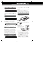
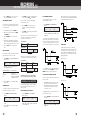
CONNECTING MICROPHONES TO THE XLR INPUT
If you use a stereo microphone, connect it to the XLR
mic inputs. If you use a single microphone, connect it to
either the left or right XLR mic input. (See page 15 for
further information about recording from a microphone
and page 17 for information about mono recording.) If
you use a microphone that requires phantom power, set
phantom mode to ‘ON’ by accessing the
INPUT menu
(see page 15).
ANALOG SOURCE RECORDING VIA THE XLR INPUT
SENDING ANALOG AUDIO TO EXTERNAL ANALOG
EQUIPMENT
CONNECTING TO DIGITAL EQUIPMENT VIA
COAXIAL OR OPTICAL
Digital source recording via COAXIAL or OPTICAL inputs.
SENDING DIGITAL AUDIO TO EXTERNAL DIGITAL
EQUIPMENT VIA COAXIAL OR OPTICAL OUTPUTS
NOTE – Ensure the digital output is turned ‘ON’ – see
page 24 for details.
CONNECTING WITH A COMPUTER VIA THE USB
INTERFACE
REMOTE CONTROL
The pin layout for the parallel remote connector is as
follows:
Parallel remote connector – pin configuration of Mini
DIN remote control:
MIC/LINE IN (L) MIC (L)
MIC/LINE IN (R) MIC (R)
MIC/LINE IN (L) LINE OUT (L)
MIC/LINE IN (R) LINE OUT (R)
LINE OUT (L) LINE IN (L)
LINE OUT (R) LINE IN (R)
DIGITAL IN DIGITAL OUT
(COAXIAL OR OPTICAL) (COAXIAL OR OPTICAL)
ONE COAXIAL OR
OPTICAL CABLE
(Both inputs indicated
with arrows)
PREPARATION cont.
PORTADISC MDP500 MiniDisc Recorder
DIGITAL OUT DIGITAL IN
(COAXIAL OR OPTICAL) (COAXIAL OR OPTICAL)
USB COMPUTER
USB PORT
USB CABLE
ONE COAXIAL OR
OPTICAL CABLE
(Both outputs
indicated with arrows)
12
CONNECTIONS
PDISC_OP.QXD 6/11/00 12:43 pm Page 13

CONNECTING MICROPHONES TO THE XLR INPUT
If you use a stereo microphone, connect it to the XLR
mic inputs. If you use a single microphone, connect it to
either the left or right XLR mic input. (See page 15 for
further information about recording from a microphone
and page 17 for information about mono recording.) If
you use a microphone that requires phantom power, set
phantom mode to ‘ON’ by accessing the INPUT menu
(see page 15).
ANALOG SOURCE RECORDING VIA THE XLR INPUT
SENDING ANALOG AUDIO TO EXTERNAL ANALOG
EQUIPMENT
CONNECTING TO DIGITAL EQUIPMENT VIA
COAXIAL OR OPTICAL
Digital source recording via COAXIAL or OPTICAL inputs.
SENDING DIGITAL AUDIO TO EXTERNAL DIGITAL
EQUIPMENT VIA COAXIAL OR OPTICAL OUTPUTS
NOTE – Ensure the digital output is turned ‘ON’ – see
page 24 for details.
CONNECTING WITH A COMPUTER VIA THE USB
INTERFACE
REMOTE CONTROL
The pin layout for the parallel remote connector is as
follows:
Parallel remote connector – pin configuration of Mini
DIN remote control:
MIC/LINE IN (L) MIC (L)
MIC/LINE IN (R) MIC (R)
MIC/LINE IN (L) LINE OUT (L)
MIC/LINE IN (R) LINE OUT (R)
LINE OUT (L) LINE IN (L)
LINE OUT (R) LINE IN (R)
DIGITAL IN DIGITAL OUT
(COAXIAL OR OPTICAL) (COAXIAL OR OPTICAL)
ONE COAXIAL OR
OPTICAL CABLE
(Both inputs indicated
with arrows)
PREPARATION cont.
PORTADISC MDP500 MiniDisc Recorder
DIGITAL OUT DIGITAL IN
(COAXIAL OR OPTICAL) (COAXIAL OR OPTICAL)
USB COMPUTER
USB PORT
USB CABLE
ONE COAXIAL OR
OPTICAL CABLE
(Both outputs
indicated with arrows)
12 13
CONNECTIONS
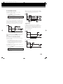
The PORTADISC can display information about the
track, record/playback time, total recorded tracks plus
time, disc space remaining, level margin, date and time
in the display window.
DISPLAY DURING STOP MODE
With the PORTADISC in stop mode, the following
information will be displayed each time you press the
DISPLAY button:
Total number of tracks and total playback time:
MD time remaining:
Level margin:
The current time of day:
The current date (the format will depend on your
setting):
When you load an MD disc, the disc name, total track
number and total playback time will be displayed
automatically. Here is an example:
Disc name:
Total track number and total playback time:
Pressing F1 will display the disc name (if available)
during stop and playback and pressing F2 will display
the current track name (if available).
DISPLAY DURING PLAY MODE
With the PORTADISC in play mode, the following
information will be displayed each time you press the
DISPLAY button:
Playback track number and playback time:
Playback track number and track time remaining:
Level margin:
Time stamped (current time of the day if there is no
time stamp recorded on the disc):
Date stamped (the current date if there is no time
stamp recorded on the disc):
DISPLAY DURING RECORD MODE
With the PORTADISC in record mode, the following
information will be displayed each time you press the
DISPLAY button:
Recording track number and recording time:
Recording track number and remaining MD time:
Level margin:
The current time of the day:
The current date:
TRK012 1:10:16 TO T DCIN
DISC 0:03:44 R E M DCIN
MARGIN L-60:R-60 DCIN
CLOCK 15:18:24 DCIN
D AT E 13/10/00 DCIN
TRK001 0:01:02 R E M DCIN
MARGIN L-09:R-11 DCIN
CLOCK 16:58/30 DCIN
D AT E 21/09/00 DCIN
REC
TRK004 0:04:05 DCIN
REC
TRK004 0:11:25 R E M DCIN
REC
MARGIN L-21:R-18 DCIN
REC
CLOCK 17:20:12 DCIN
MONDAY’S NEWS
TRK012 1:10:16 TO T DCIN
TRK001 0:02:05 DCIN
REC
D AT E 01/12/00 DCIN
LCD DISPLAY

PREPARATION cont.
PORTADISC MDP500 MiniDisc Recorder
DISPLAY BACK LIGHT
Press LIGHT to turn on the display back light for 5
seconds or, if you press and hold the
LIGHT button, the
light will stay on permanently.
NOTE – We recommend minimal use of the display light
when the PORTADISC is powered by batteries. This will
maximise battery life.
DISPLAY CONTRAST
1. Press SETUP until ‘DISPLAY CONTRAST’ is
displayed.
2. Press
F1 to choose the setting you want from ‘+1’,
‘+2’, ‘+3’, ‘+4’ and ‘+5’ (5 is the darkest).
3. Press the F2 button to confirm and then press F3
to exit this page.
14
DISPLAY CONTRAST
+3 SET EXIT
PDISC_OP.QXD 6/11/00 12:43 pm Page 15

15
RECORDING
PORTADISC MDP500 MiniDisc Recorder
1. Press the INPUT button once to recall ‘SOURCE’
mode in order to select the correct input source
settings.
2. Press
F1 and F3 to choose ‘MIC’. Then press F2 to
confirm.
You can select the input source for both left and right
channels individually:
SOURCE mode Input source setting for left & right
OFF Input source off
MIC External microphone
LINE Line input
DIGITAL Digital input
INTMIC Internal microphone
Once your input source is selected as ‘MIC’, the
following settings will also be available by scrolling
through the
INPUT menu pages (by pressing INPUT):
MIC ATTENUATION MODE
In ‘MIC-Att’ mode, you can select the attenuation to be
applied to the external microphones. Use this mode
when using high output microphones.
1. Press the
INPUT button once again to recall
‘MIC-Att’ mode:
2. Press
F1 and F3 to choose the attenuation from
‘0’, ‘-15dB’, and ‘-30dB’. Then press
F2 to confirm.
MIC-Att mode Attenuation setting
0dB No attenuation
-15dB 15dB attenuation
-30dB 30dB attenuation
BASSCUT MODE
With this mode you can select the bass roll-off
frequency. Use this mode to minimise rumble, wind
noise or humming induced by a power source.
1. Press the
INPUT button once again to recall
‘BASSCUT’ mode:
2. Press
F1 and F3 to choose the bass cut frequency
from ‘OFF’, ‘75Hz’, and ‘150Hz’. Then press
F2 to
confirm.
BASSCUT mode Bass cut setting
OFF Off
75Hz Attenuate below 75Hz
150Hz Attenuate below 150Hz
LIMITER MODE
This mode selects the limiter function and automatic
gain control. In ‘GANGED’ mode, limiting on either
channel will affect the other channel by the same
amount, thereby maintaining the stereo image.
1. Press the
INPUT button once again to recall
‘LIMITER’ mode:
2. Press
F1 and F3 to choose the limiter setting from
‘ON’, ‘OFF’, ‘GANGED’, and ‘AGC’. Then press
F2 to
confirm.
LIMITER mode Limiter setting
ON On
OFF Off
GANGED Ganged limiter applied
AGC Automatic gain control (
REC
LEVEL
control is bypassed)
The Automatic Gain Control function automatically sets
the record level of an analog input in order to achieve
an optimum signal level. In this mode, the record level
control is bypassed.
NOTE – If one channel is set to GANGED or AGC, then
the other channel is automatically set to the same. If
you subsequently decide to set either channel to limiter
‘ON’ or ‘OFF’, you will need to select ‘ON’ or ‘OFF’ for
both channels using
F1 and F3 before setting this with
the
F2 button.
PHANTOM MODE
The PORTADISC can supply +48V phantom power to
the external microphones.
1.Press the
INPUT button once again to recall
‘PHANTOM’ mode:
2. Press
F1and F3to choose the phantom power
setting from ‘ON’ or ‘OFF’. Then press
F2 to
confirm.
PHANTOM mode Phantom power setting
ON On
OFF Off
RECORDING FROM A MICROPHONE
INPUT-L SOURCE INPUT-R
MIC SET MIC
INPUT-L MIC-Att INPUT-R
0dB SET 0dB
INPUT-L BASSCUT INPUT-R
OFF SET OFF
INPUT-L LIMITER INPUT-R
ON SET ON
INPUT-L PHANTOM INPUT-R
ON SET ON
PDISC_OP.QXD 6/11/00 12:44 pm Page 16

16
1. Press the INPUT button once to recall ‘SOURCE’
mode.
2. Press
F1 and F3 to choose ‘LINE’. Then press F2
to set-up.
Once your input source is selected as ‘LINE’, the limiter
setting will also be available by pressing
INPUT. See the
previous section for further details about the limiter
function.
1. Press the
INPUT button once to recall ‘SOURCE’
mode.
2. Press
F1 and F3 to choose ‘DIGITAL’. Then press
F2 to set-up.
Once your input source is selected as ‘DIGITAL’, the
digital input mode setting will also be available by
pressing
INPUT:
1. Press
INPUT again to recall DIGITAL INPUT? mode.
2. Press
F1 to select the correct digital input source
from ‘COAXIAL’, ‘OPTICAL’ or ‘USB’. Then press
F2
to confirm and F3 to exit..
DIGITAL INPUT mode Digital input setting
COAXIAL Coaxial input
OPTICAL Optical input
USB Universal Serial Bus input
NOTE – If the digital source is interrupted (e.g., due to an
intermittent connection), recording will automatically
enter a record suspend mode and ‘Din Unlock!’ will be
displayed. Recording will resume as soon as the signal is
restored. If one channel is set to ‘DIGITAL’, the other
channel will automatically be set to the same. If you
subsequently decide to change this setting, you must first
select the required source for both the left and right
channels using
F1 and F3 before pressing F2 to confirm.
1. Press INPUT button once to recall SOURCE mode.
2. Press
F1 or F3 to choose ‘INTMIC’. Then press F2
to set-up.
The internal mono microphone is suitable for use identing
tracks, etc.
NOTE – If one channel is set to ‘INTMIC’, the other
channel will automatically be set to the same. If you
subsequently decide to change this setting, you must first
select the required source for both the left and right
channels using
F1 and F3 before pressing F2 to confirm.
1. Load the MD disc to be used for recording into the
opening as shown below:
For best results, we recommend HHB MD74 or HHB
MD80 (74 and 80 minute) professional MD media.
2. Adjust the
REC LEVEL control for the appropriate
recording level. This control is not active if the
‘LIMITER’ mode is set to ‘AGC’ (Automatic Gain
Control), internal ‘INTMIC’ is selected, or if a digital
signal is being recorded.
3. Slide the
RECORD button to the right to start
recording if you want to record immediately.
However, if you first want to enter record pause
mode, press the
PAUSE button first, then slide the
RECORD button. When you press the PAUSE
button again, the PORTADISC will start recording:
RECORDING FROM LINE SOURCES
RECORDING FROM DIGITAL SOURCES
INPUT-L SOURCE INPUT-R
LINE SET LINE
INPUT-L SOURCE INPUT-R
DIGITAL SET DIGITAL
DIGITAL INPUT?
COAXIAL SET EXIT
INPUT-L SOURCE INPUT-R
INTMIC SET INTMIC
BASIC RECORDING
Load the MD disc with the
arrows facing towards the slot.
To allow recording, the record
protection tag on the disc must
be in the correct position.
RECORDING cont.
PORTADISC MDP500 MiniDisc Recorder
RECORDING FROM MONO INTERNAL MIC
PDISC_OP.QXD 6/11/00 12:44 pm Page 17

1716
• RECORD Start recording
• PAUSE, RECORD Record pause
followed by PAUSE Start recording
4. Adjust the recording levels so that the peak level
meters do not go beyond 0dB (marked ‘OVR’ in the
top right of the diagram below). If the recording
level goes above 0dB, distortion to the recorded
material may occur.
5. Press the STOP button to stop recording. Or press
the PAUSE button to pause recording. If you press
the PAUSE button once again in record pause
mode, the PORTADISC will start recording again.
MONO RECORDING
You can double the recording time on an MD disc by
using the mono recording mode.
1. Recall ‘REC MODE ?’ by pressing the SYSTEM
button once.
2. Press F1 to choose ‘MONO’. Then press F2 to
confirm and F3 to exit.
NOTE – The left and right channels will be added and
recorded as a mono signal.
ONE-TOUCH SETUP
Use the SETUP button to quickly configure the
PORTADISC for mic, line or digital recordings.
1. Press the SETUP button once to recall ‘OPEN
SETUP’ mode.
2. The following setup options are available by scrolling
through F1 from the ‘OPEN SETUP?’ menu page.
Press F2 to select.
SETUP PORTADISC settings
USER1 - USER5 5 user-defined settings
MIC REC Microphone recording setup
LINE REC Line recording setup
DIGI REC Digital recording setup
You can save your input and system settings (which
were made by using the INPUT and SYSTEM buttons)
into 5 user memories and then easily recall them by
opening the user memories.
HOW TO SAVE
5 user memories are available, named ‘USER 1’ to
‘USER 5’.
1. Make your record mode setting using the INPUT
button and the SYSTEM button.
2. Press the SETUP button until ‘SAVE SETUP’ is
displayed.
3. Press F1 to choose the user memory from USER
1-5. Then press F2 to save.
HOW TO OPEN
You can open your pre-set record mode, which you
saved in the user memories from USER 1-5.
1. Press the SETUP button until ‘OPEN SETUP’ is
recalled.
2. Press F1 to choose the user memory from USER
1-5. Then press F2 to open.
6 SECONDS PRE-RECORDING
This function enables you to record 6 seconds of audio
from the internal memory buffer prior to pressing
RECORD. This is a useful function for minimising the
chance of missing the beginning of a take.
1. Press the SYSTEM button until ‘PRE-RECORD?’
mode is recalled.
2. Press F1 until ‘YES’ is displayed. Then press F2 to
set-up.
3. Enter record pause mode by pressing PAUSE
before sliding the RECORD button.
CAUTION – For the pre-record mode to work, you need to
wait at least 6 seconds after preparing the record pause
mode in order to pre-load the buffer. The PORTADISC will
not record the full 6 seconds of audio otherwise.
4. Press PAUSE to start recording. The PORTADISC
will record the audio, including 6 seconds of audio
prior to the start of the recording.
RECMODE
M O N O SET EXIT
1. Press the INPUT button once to recall ‘SOURCE’
mode.
2. Press F1 and F3 to choose ‘LINE’. Then press F2
to set-up.
Once your input source is selected as ‘LINE’, the limiter
setting will also be available by pressing INPUT. See the
previous section for further details about the limiter
function.
1. Press the INPUT button once to recall ‘SOURCE’
mode.
2. Press F1 and F3 to choose ‘DIGITAL’. Then press
F2 to set-up.
Once your input source is selected as ‘DIGITAL’, the
digital input mode setting will also be available by
pressing INPUT:
1. Press INPUT again to recall DIGITAL INPUT? mode.
2. Press F1 to select the correct digital input source
from ‘COAXIAL’, ‘OPTICAL’ or ‘USB’. Then press F2
to confirm and F3 to exit..
DIGITAL INPUT mode Digital input setting
COAXIAL Coaxial input
OPTICAL Optical input
USB Universal Serial Bus input
NOTE – If the digital source is interrupted (e.g., due to an
intermittent connection), recording will automatically
enter a record suspend mode and ‘Din Unlock!’ will be
displayed. Recording will resume as soon as the signal is
restored. If one channel is set to ‘DIGITAL’, the other
channel will automatically be set to the same. If you
subsequently decide to change this setting, you must first
select the required source for both the left and right
channels using F1 and F3 before pressing F2 to confirm.
1. Press INPUT button once to recall SOURCE mode.
2. Press F1 or F3 to choose ‘INTMIC’. Then press F2
to set-up.
The internal mono microphone is suitable for use identing
tracks, etc.
NOTE – If one channel is set to ‘INTMIC’, the other
channel will automatically be set to the same. If you
subsequently decide to change this setting, you must first
select the required source for both the left and right
channels using F1 and F3 before pressing F2 to confirm.
1. Load the MD disc to be used for recording into the
opening as shown below:
For best results, we recommend HHB MD74 or HHB
MD80 (74 and 80 minute) professional MD media.
2. Adjust the REC LEVEL control for the appropriate
recording level. This control is not active if the
‘LIMITER’ mode is set to ‘AGC’ (Automatic Gain
Control), internal ‘INTMIC’ is selected, or if a digital
signal is being recorded.
3. Slide the RECORD button to the right to start
recording if you want to record immediately.
However, if you first want to enter record pause
mode, press the PAUSE button first, then slide the
RECORD button. When you press the PAUSE
button again, the PORTADISC will start recording:
RECORDING FROM LINE SOURCES
RECORDING FROM DIGITAL SOURCES
INPUT-L SOURCE INPUT-R
LINE SET LINE
INPUT-L SOURCE INPUT-R
DIGITAL SET DIGITAL
DIGITAL INPUT?
COAXIAL SET EXIT
INPUT-L SOURCE INPUT-R
INTMIC SET INTMIC
BASIC RECORDING
Load the MD disc with the
arrows facing towards the slot.
To allow recording, the record
protection tag on the disc must
be in the correct position.
RECORDING cont.
PORTADISC MDP500 MiniDisc Recorder
SAVE SETUP
USER1 SAVE EXIT
OPENSETUP
USER1 OPEN EXIT
OPENSETUP
MICREC OPEN EXIT
TIME = 0 SECONDS TIME +6 SECONDS
ACTUAL RECORDING
BEGINS HERE
RECORD BUTTON
IS PRESSED
SETUP MENU
USEFUL RECORDING FUNCTIONS
PRE-RECORD?
YE S SET EXIT
RECORDING FROM MONO INTERNAL MIC

1918
RECORDING cont.
PORTADISC MDP500 MiniDisc Recorder
AUTO INCREMENT FUNCTION
The function enables new tracks to be created
automatically during recording.
1. Press SYSTEM until ‘TRACK-INCREMENT?’ is
displayed.
2. Press F1 to choose the auto increment setting
from ‘AUTO’ or ‘MANUAL’. Then press F2 to set-up
and F3 to exit.
If set to ‘AUTO’, a new track will be created if the input
signal level drops below and then rises above the level
set in the threshold level menu page (see previous page
for details). The signal level must drop for more than
two seconds before rising again to create a new track:
If set to ‘MANUAL’, this feature will be disabled and new
tracks are only created when MARK is pressed. The
MARK button will also function in ‘AUTO’ mode.
AUTO-START/CUT RECORDING FUNCTION
This function, ideal for environmental noise monitoring,
operates as follows:
• The PORTADISC will automatically start recording
when the threshold level setting is exceeded.
• Recording will automatically pause when the audio
level drops below the threshold level setting for
more than 30 seconds.
The PORTADISC must be in record pause mode for the
auto-start function to operate.
1.
Press the SYSTEM button until ‘AUTO-START/CUT?’
is displayed.
2. Press F1 to choose ‘YES’. Then press F2 to set-up
and F3 to exit.
When using the auto-start/cut function with a digital
input, the threshold level setting will default to -80dBFS,
as illustrated below (with auto-start/cut on):
SILENCE TRIM
In addition, with auto-start/cut set to ‘ON’ during
recording, if the audio level drops below the threshold
level setting for more than 5 seconds and then rises
above the threshold, the PORTADISC will ‘silence trim’
the silent region to 5 seconds in length. ‘Silence Trim’
will be briefly displayed.
Before silence trim:
After silence trim:
5. Press the PAUSE button to enter record pause
mode. Or press STOP to stop recording.
INPUT MONITOR FUNCTION
You can monitor the incoming audio signal even when
you are not recording (the input is always monitored in
record pause mode).
1. Eject the MD disc by pressing the OPEN button.
2. Make your record mode setting using the INPUT
and SYSTEM buttons.
3. Slide the RECORD button to enter the monitor
mode.
4. The input audio signal will appear on the display
meter and on both the analog and digital outputs,
whichever analog or digital input source you choose.
5. Press the STOP button to cancel the monitor
mode.
PEAK HOLD METER
The level bar meter display shows the audio level with
peak hold functions. It can be set as follows:
1. Press SETUP until the ‘PEAK HOLD METER’ setup
mode is recalled:
2. Press F1 to choose the setting you want from
‘OFF’, ‘2SECOND’, and ‘ON’.
PEAK HOLD METER mode Peak hold setting
OFF Peaks not held
2SECOND Peaks held for 2 seconds
ON Peaks held until the STOP
or
F3
button is pressed
3. Press the F2 button to set-up. Then press F3 to
exit the mode.
OVERWRITE MODE
It is possible to record directly over previously recorded
tracks without needing to erase them first.
1. Press SYSTEM until ‘OVERWRITE MODE ?’ is
displayed.
2. Press F1 to select the overwrite setting from ‘ON’
or ‘OFF’.
3. Press the F2 button to set-up. Then press F3 to
exit the mode.
4.
Press PAUSE, then select the track that you want to
record over using the AMS and buttons.
NOTE – If no track is selected, recording will begin
automatically over track 1.
5. Slide the RECORD switch to the right to enter
record pause mode. ‘Overwrite!’ will be briefly
displayed.
6. Press PAUSE to begin recording. ‘Overwrite!’ will be
briefly shown again.
If the new track is shorter than the track which is being
overwritten, the remaining part of the old track will
become the next track on the disc:
If the new track is longer than the track which is being
overwritten, the next track will also be recorded over:
CAUTION – Please be aware that using overwrite
mode can permanently remove existing recordings.
The threshold level setting sets the levels from which
both the auto increment and the auto start/cut
functions operate.
RECORD THRESHOLD LEVEL SETTING
1. Press the SYSTEM button until ‘THRESHOLD
LEVEL’ is displayed.
2. Press F1 to choose the threshold level from
‘-30dB’, ‘-40dB’, ‘-50dB’ or ‘-60dB’. Then press F2
to set-up and F3 to exit.
PEAK HOLDMETER ?
OFF SET EXIT
OVERWRITE MODE ?
OFF SET EXIT
s
s
y
s
s
y
TRACK 1
BEFORE OVERWRITING:
TRACK 2
TRACK 1
AFTER OVERWRITING:
TRACK 2
NEW TRACK 2
TRACK 3
(OLD TRACK 2)
TRACK 1
BEFORE OVERWRITING:
TRACK 2
TRACK 3
TRACK 1
AFTER OVERWRITING:
TRACK 2
NEW TRACK 2
END OF
TRACK 3
THRESHOLD LEVEL FUNCTIONS
THRESHOLD LEVEL
-30dB SET EXIT
TRACK-INCREMENT?
AU TO SET EXIT
AUTO-STA RT/CUT?
YE S SET EXIT

19
AUTO INCREMENT FUNCTION
The function enables new tracks to be created
automatically during recording.
1. Press
SYSTEM until ‘TRACK-INCREMENT?’ is
displayed.
2. Press
F1 to choose the auto increment setting
from ‘AUTO’ or ‘MANUAL’. Then press
F2 to set-up
and
F3 to exit.
If set to ‘AUTO’, a new track will be created if the input
signal level drops below and then rises above the level
set in the threshold level menu page (see previous page
for details). The signal level must drop for more than
two seconds before rising again to create a new track:
If set to ‘MANUAL’, this feature will be disabled and new
tracks are only created when
MARK is pressed. The
MARK button will also function in ‘AUTO’ mode.
AUTO-START/CUT RECORDING FUNCTION
This function, ideal for environmental noise monitoring,
operates as follows:
• The PORTADISC will automatically start recording
when the threshold level setting is exceeded.
• Recording will automatically pause when the audio
level drops below the threshold level setting for
more than 30 seconds.
The PORTADISC must be in record pause mode for the
auto-start function to operate.
1.
Press the SYSTEM button until ‘AUTO-START/CUT?’
is displayed.
2. Press
F1 to choose ‘YES’. Then press F2 to set-up
and
F3 to exit.
When using the auto-start/cut function with a digital
input, the threshold level setting will default to -80dBFS,
as illustrated below (with auto-start/cut on):
SILENCE TRIM
In addition, with auto-start/cut set to ‘ON’ during
recording, if the audio level drops below the threshold
level setting for more than 5 seconds and then rises
above the threshold, the PORTADISC will ‘silence trim’
the silent region to 5 seconds in length. ‘Silence Trim’
will be briefly displayed.
Before silence trim:
After silence trim:
TRACK-INCREMENT?
AUTO SET EXIT
AUTO-START/CUT?
YES SET EXIT
PDISC_OP.QXD 6/11/00 12:44 pm Page 20

1. Load the MD disc to be used for playback into the
disc opening.
2. Press the PLAY button to start playback.
3. Press the
PAUSE or STOP buttons to pause or
stop playback.
4. During playback, press the AMS button once
to locate the beginning of the next track. Press the
AMS button once to locate the beginning of
the current track. If you repeatedly press either of
the AMS buttons, the track will continuously jump in
the direction indicated. If the
AMS button is
pressed repeatedly from Track 1, the PORTADISC
will ‘wrap round’ to the last track.
FAST SEARCH FUNCTION
You can playback a track in fast search mode by holding
down either the
REW or FF buttons. If you hold the
buttons for more than 5 seconds, playback will enter an
extra-fast search mode.
DIRECT TRACK SELECT FUNCTION
You can locate a track you want by its number in order
to play it back.
1. During stop mode, press
AMS or AMS
repeatedly to choose the track number.
2. Press
PLAY to start playback of the required track.
REPEAT ONE OR REPEAT ALL FUNCTION
You can repeatedly play back a particular track or all
the tracks from the MD disc.
1. Press
SYSTEM button until ‘REPEAT MODE ?’ is
displayed.
2. Press
F1 to choose the repeat mode from ‘ALL’ or
‘ONE’. Then press
F2 to set-up.
3. Press the
PLAY button to begin playback.
4. The PORTADISC will repeatedly play back a
particular track or all tracks accordingly. Whilst in
the repeat mode, either ‘ONE’ or ‘ALL’ will be shown
in the top right hand corner of the display.
5. If you want to cancel the repeat mode, choose ‘OFF’
for the repeat mode as described above.
REPEAT A-B
You can repeatedly play back a certain portion within a
track.
1. Press the
SYSTEM button until ‘REPEAT MODE ?’
is displayed.
2. Press
F1 to choose ‘A-B’. Then press F2 to set-up.
3. Play back the track you want to repeat. While
playing back the track, ‘A-B’ will be shown in the top
right hand corner of the display.
4. During playback, press the F2 button at the time
that you want the repeat function to start. As this
point has now been registered as A, ‘Repeat A-’ will
be shown momentarily on the display.
5. Continue playback or press the
FF button to reach
the place where you want the repeat function to
end. Then press the
F2 button to set-up the repeat
end point – point B. The PORTADISC will now repeat
the portion between point A and point B.
‘Repeat A-B’ will be shown on the display
momentarily while rewinding from B to A.
6. You can also change points A and B during replay. If
you press
F2 again during replay, the point you had
previously set as B will now become a new point A
and you will be able to register a new point B by
following the procedure mentioned in point 5 above.
7. If you want to reset the repeat A-B setting, press
the
STOP button, or change the playback track
using the
AMS or AMS buttons.
With this mode, the PORTADISC will pause between
tracks. This mode is useful if you want to playback
particular tracks one at a time rather than continuously;
ideal for broadcast or theatre productions.
1. Press the SYSTEM button until ‘AUTO-PAUSE?’ is
recalled.
2. Press
F1 to choose ‘YES’. Then press F2 to set-up.
3. With auto-pause on, the PORTADISC will
automatically pause at the end of the current track.
If you wish to replay the same track, press
AMS
once, then press the PLAY button. If you want to
start playing back the next track, simply press the
PLAY button. The PORTADISC will stay in pause
mode after playing back the next track.
4. To cancel the auto-pause mode, set this mode to
‘NO’ in the system menu.
PLAYBACK
PORTADISC MDP500 MiniDisc Recorder
20
▲
▲
❙
▲
▲
❙
▲
▲
❙
▲
▲
❙
▲
▲
❙
REPEAT MODE ?
ALL SET EXIT
REPEAT MODE ?
A-B SET EXIT
AUTO-PAUSE?
YES SET EXIT
▲
▲
❙
▲
▲
❙
▲
▲
❙
NORMAL PLAYBACK
REPEAT FUNCTIONS
AUTO PAUSE MODE
PDISC_OP.QXD 6/11/00 12:44 pm Page 21
Page is loading ...
Page is loading ...
Page is loading ...
Page is loading ...
Page is loading ...
Page is loading ...
Page is loading ...
Page is loading ...
Page is loading ...
Page is loading ...
Page is loading ...
Page is loading ...
-
 1
1
-
 2
2
-
 3
3
-
 4
4
-
 5
5
-
 6
6
-
 7
7
-
 8
8
-
 9
9
-
 10
10
-
 11
11
-
 12
12
-
 13
13
-
 14
14
-
 15
15
-
 16
16
-
 17
17
-
 18
18
-
 19
19
-
 20
20
-
 21
21
-
 22
22
-
 23
23
-
 24
24
-
 25
25
-
 26
26
-
 27
27
-
 28
28
-
 29
29
-
 30
30
-
 31
31
-
 32
32


HHB comm HHB MDP500 User manual
- Category
- CD players
- Type
- User manual
Ask a question and I''ll find the answer in the document
Finding information in a document is now easier with AI
Related papers


Other documents
-
 HHB Portadisc MDP500 Operating Instructions Manual
-
Kenwood MD-MT877W User manual
-
Sharp MD-MT877 User manual
-
 HHB CDR830 PLUS Technical Bulletin
-
Marantz PMD680 User manual
-
Sony Walkman PCM-M1 User manual
-
Lenco CD-214 Owner's manual
-
 Fischer Amps In Ear Body Pack XL Owner's manual
-
Fostex CR500 User manual
-


