Page is loading ...

1F87-361
Programmable Electronic Digital Thermostat
INSTALLATION AND
OPERATION INSTRUCTIONS
FAILURE TO READ AND FOLLOW ALL INSTRUCTIONS CAREFULLY
BEFORE INSTALLING OR OPERATING THIS CONTROL COULD CAUSE
PERSONAL INJURY AND/OR PROPERTY DAMAGE.
DESCRIPTION
• Temperatureoverrideuntilnextprogramperiod
• Manualprogramoverride(HOLDtemperature)
• TemporaryHOLD
• °F/°Cconvertibility
• Temperaturerange45°to90°F
• RC,RH,C,W,Y,G,OandBterminals
• OptionalCterminal(DualPoweroption)
• BandOterminalsforsinglestageheatpumps(noauxiliary
heat)ordamperoperation
• Programstorageincaseofpowerloss
• 2“AA”Energizer
®
alkalinebatteriesincluded
Operator: Save these instructions for future use!
Your new White-Rodgers 7-Day DigitalThermostat uses the
technology ofa solid-state microcomputer to provideprecise
time/temperaturecontrol.Thisthermostatoffersyoutheexibility
todesignheatingandcoolingprogramsthattyourneeds.
Features:
• Separateprogramforeachdayoftheweekwithfourseparate
time/temperatureperiodsperday
• Simultaneousheatandcoolprogramstorage
• Preprogrammedtemperaturecontrol
• Backlitdisplay
• LCDcontinuouslydisplayssetpoint,andalternatelydisplays
timeandroomtemperature
PRECAUTIONS
Thisthermostatisintendedforusewithalowvoltagesystem;
donotusethisthermostatwithalinevoltagesystem.Ifindoubt
aboutwhetheryourwiringismillivolt,line,orlowvoltage,haveit
inspectedbyaqualiedheatingandairconditioningcontractor
orelectrician.
Donotexceedthespecicationratings.
Allwiringmustconformtolocalandnationalelectricalcodes
andordinances.
Thiscontrolisaprecisioninstrument,andshouldbehandled
carefully.Roughhandlingordistortingcomponentscouldcause
thecontroltomalfunction.
▲
!
CAUTION
To prevent electrical shock and/or equipment damage,
disconnect electric power to system at main fuse or
circuit breaker box until installation is complete.
▲
!
WARNING
Do not use on circuits exceeding specified voltage.
Higher voltage will damage control and could cause
shock or fire hazard.
Do not short out terminals on gas valve or primary
control to test. Short or incorrect wiring will damage
thermostat and could cause personal injury and/or
property damage.
Thermostat installation and all components of the system
shall conform to Class II circuits per the NEC code.
SPECIFICATIONS
ELECTRICAL DATA
Electrical Rating:
8to30VAC50/60Hz.orD.C.
0.05to1.0Amps(Loadperterminal)
1.5 Amps Maximum Total Load(Allterminalscombined)
THERMAL DATA
Setpoint Temperature Range:
45°Fto90°F(7°Cto32°C)
Operating Ambient Temperature Range:
32°Fto105°F
Operating Humidity Range:
0to90%RH(non-condensing)
Shipping Temperature Range:
-4°Fto149°F
APPLICATIONS
Forusewith:
• Standardheat/coolorheatonlysystems
• Electricheatsystems
• Gasoroilredsystems
• Gassystemswithintermittentignitiondevices(I.I.D.)
and/orventdampers
• Hydronic(hotwaterorsteam)systems
• Single-stageheatpumpsystems(noauxiliaryheat)
• Millivoltsystems
DO NOT USE WITH:
• Multi-stagesystems
• Systemsexceeding30VACand1.5amps
• 3-wirezonedhydronicheatingsystems
PART NO. 37-6763B
Replaces37-6763A
1006
www.white-rodgers.com

2
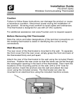
Mounting
holes
Mounting
holes
Electric/Gas
switch
Screw anchors
INSTALLATION
REMOVE OLD THERMOSTAT
1. Shutoffelectricityatthemainfuseboxuntilinstallationis
complete.Ensurethatelectricalpowerisdisconnected.
2. Removethefrontcoveroftheoldthermostat.With wires
still attached, removewallplate fromthe wall. If the old
thermostathasawallmountingplate,removethethermostat
andthewallmountingplateasanassembly.
3. Identify each wire attached to the old thermostat using
the labels enclosed with the new thermostat.
4. Disconnectthewiresfromoldthermostatoneatatime.DO
NOT LET WIRES FALL BACK INTO THE WALL.
5. Installnewthermostatusingthefollowingprocedures.
ATTENTION!
Thisproductdoesnotcontainmercury.However,thisproduct
mayreplaceaunitwhichcontainsmercury.
Donotopenmercurycells.Ifacellbecomesdamaged,donot
touchanyspilledmercury.Wearingnonabsorbentgloves,take
upthespilledmercurywithsandorotherabsorbentmaterialand
placeintoacontainerwhichcanbesealed.Ifacellbecomes
damaged,theunitshouldbediscarded.
Mercurymustnotbediscardedinhouseholdtrash.Whenthe
unitthisproductisreplacingistobediscarded,placeinasuit-
ablecontainer.Refertowww.white-rodgers.comforlocationto
sendproductcontainingmercury.
ELECTRIC HEAT OR SINGLE-STAGE
HEAT PUMP SYSTEMS
Thisthermostatisconguredfromthefactorytooperateaheat/
cool,fossilfuel(gas,oil,etc.),forcedairsystem.Itiscongured
correctlyforanysystemthatDOESNOTrequirethethermostat
toenergizethefanonacallforheat.Ifyoursystemisanelectric
heatorheat-pumpsystemthatREQUIRESthethermostatto
turnonthefanonacallforheat,locatetheELECTRIC/GAS
switch onthebackof the thermostat(seeg.1)andswitch
it to the ELECTRIC position. This will allow the thermostat
toenergizethe fanimmediately on a callforheat.Ifyouare
unsureiftheheating/coolingsystemrequiresthethermostatto
controlthefan,contactaqualiedheatingandairconditioning
serviceperson.
ATTACH THERMOSTAT BASE TO WALL
1. Removethepackingmaterialfromthethermostat.Gently
pullthecoverstraightoffthebase.Forcingorpryingonthe
thermostatwillcausedamagetotheunit.Ifnecessary,move
theelectricheatswitch(seeELECTRIC HEAT SYSTEMS,
above).
2. Connectwiresbeneathterminalscrewsonbaseusingap-
propriatewiringschematic(seegs.2through7).
3. Placebaseoverholeinwallandmarkmountingholeloca-
tionsonwallusingbaseasatemplate.
4. Movebaseoutoftheway.Drillmountingholes.
5. Fastenbaselooselytowall,asshowning.1,usingtwo
mounting screws. Place a level against bottom of base,
adjustuntillevel,andthentightenscrews.(Levelingisfor
appearanceonlyandwillnotaffectthermostatoperation.)
Ifyouareusingexistingmountingholes,orifholesdrilled
aretoolargeanddonotallowyoutotightenbasesnugly,
useplasticscrewanchorstosecuresubbase.
6. Pushexcesswireintowallandplugholewithare-resistant
material(suchasberglassinsulation)topreventdraftsfrom
affectingthermostatoperation.
BATTERY LOCATION
2“AA”alkalinebatteriesareincludedinthethermostatatthe
factorywithabatterytagtopreventpowerdrainage.You must
remove the battery tag to engage the batteries.
If“BATT”or“CHANGE ”isdisplayed,thebatteriesare
lowandshouldbereplacedwithfresh“AA”Energizer
®
alkaline
batteries.Toreplacebatteries,installthebatteriesalongthetop
ofthebase(seeFig.1).Thebatteriesmustbeinstalledwiththe
positive(+)endtotheleft.
HYDRONIC (HOT WATER OR STEAM)
HEATING SYSTEMS
Thisthermostatissettooperateproperlywithaforced-airheat-
ingsystem.Ifyouhaveahydronicheatingsystem(asystem
thatheatswithhotwaterorsteam),youmustsetthethermostat
tooperateproperlywithyoursystem.Changethesecondop-
tioninthecongurationmenutoSL(seeCONFIGURATION
MENU,page4).
CHECK THERMOSTAT OPERATION
If at any time during testing your system does not operate
properly,contactaqualiedserviceperson.
Turnonpowertothesystem.
Fan Operation
Ifyoursystemdoes nothaveaGterminalconnection,skipto
Heating System.
1. MoveFANswitchtoON position.Theblowershouldbegin
tooperate.
2. Move FAN switch to AUTO position. The blower should
stopimmediately.
Figure 1. Thermostat Base

3
RH
Y
24 VAC
120 VAC
Hot
Neutral
TRANSFORMER
THERMOSTAT
SYSTEM
G W
Figure 3. Typical wiring diagram for
cool only, 3-wire, single transformer systems
Cooling
System
Fan
Relay
RCOB
C
‡
JUMPER
WIRE
Figure 2. Typical wiring diagram for
heat only, 3-wire, single transformer systems
RH
Y
24 VAC
120 VAC
Hot
Neutral
THERMOSTAT
SYSTEM
G W
TRANSFORMER
Heating
System
Fan
Relay
RC
JUMPER
WIRE
OC
‡
B
For 2-wire Heat only,
attach to RH and W
NOTE
RH
Y
24 VAC
120 VAC
Hot
Neutral
THERMOSTAT
SYSTEM
G W
Figure 5. Typical wiring diagram for
heat/cool, 5-wire, two-transformer systems
HEATING
TRANSFORMER
Heating
System
Fan
Relay
Cooling
System
RC
24 VAC
120 VAC
Hot
Neutral
COOLING TRANSFORMER
OBC
‡
RH
Y
24 VAC
120 VAC
Hot
Neutral
THERMOSTAT
SYSTEM
G W
Figure 7. Typical wiring diagram for heat pump
with reversing valve energized in HEAT
TRANSFORMER
Reversing
Valve*
RCO
B
C
‡
JUMPER
WIRE
Compressor
Contactor
JUMPER
WIRE
* Reversing valve is energized when the
system switch is in the HEAT position
Fan
Relay
‡
The24VoltneutralconnectiontoterminalConthethermostatisnotrequiredifthebatteriesarereplacedoncea
yearwithfresh“AA”Energizer
®
alkalinebatteries.
Heating System
1. MoveSYSTEMswitchtoHEATposition.Iftheheatingsystem
hasastandingpilot,besuretolightit.
2. Press
toadjustthermostatsettingaboveroomtempera-
ture.Theheatingsystemshouldbegintooperate.
3. Press
toadjustthermostatsettingbelowroomtempera-
ture.Theheatingsystemshouldstopoperating.
To prevent compressor and/or property damage, if the
outdoor temperature is below 50°F, DO NOT operate
the cooling system.
1. MoveSYSTEMswitchtoCOOLposition.
2. Press
toadjustthermostatsettingbelowroomtempera-
ture.Theblowershouldcomeonimmediatelyonhighspeed,
followedbycoldaircirculation
3. Press
toadjustthermostatsettingaboveroomtempera-
ture.Thecoolingsystemshouldstopoperating.
Cooling System
▲
!
CAUTION
INSTALLATION
RH
Y
24 VAC
120 VAC
Hot
Neutral
THERMOSTAT
SYSTEM
G W
Figure 4. Typical wiring diagram for
heat/cool, 4-wire, single transformer systems
TRANSFORMER
Heating
System
Fan
Relay
Cooling
System
RC
JUMPER
WIRE
OC
‡
B
RED jumper wire (provided with thermostat) must be
connected between thermostat RH and RC terminals
for proper thermostat operation with this system.
NOTE
RH
Y
24 VAC
120 VAC
Hot
Neutral
THERMOSTAT
SYSTEM
G W
Figure 6. Typical wiring diagram for heat pump
with reversing valve energized in COOL
TRANSFORMER
Reversing
Valve*
RCOBC
‡
JUMPER
WIRE
Compressor
Contactor
JUMPER
WIRE
* Reversing valve is energized when the
system switch is in the COOL position
Fan
Relay

4
Before you begin programming your thermostat, you should
befamiliarwithitsfeaturesandwiththedisplayandtheloca-
tionandoperationofthethermostatbuttons.Yourthermostat
consistsoftwoparts:thethermostat coverandthebase.To
removethecover,pullitstraightoutfromthebase.Toreplace
thecover,lineupthecoverwiththebaseandpressuntilthe
coversnapsontothebase.
The Thermostat Buttons and Switches
1
Raisestemperaturesetting.
2
Lowerstemperaturesetting.
3
TIMEbutton.
4
PRGM(program)button.
5
RUN(runprogram)button.
6
HOLDtemperaturebutton.
7
FANswitch(ON,AUTO).
8
SYSTEMswitch(COOL,OFF,HEAT).
The Display
9
Indicatesdayoftheweek.
10
Flame icon( ) is displayed when the SYSTEM switch
isintheHEATposition.Snowflake icon(
)isdisplayed
(non-ashing)whentheSYSTEMswitchisintheCOOL
position.Snowflakeisdisplayed(ashing)ifthethermostat
isinlockoutmodetopreventthecompressorfromcycling
tooquickly.
11
Displays “BATT” or “CHANGE ” when the 2 “AA”
batteriesarelowandshouldbereplaced.Only“BATT” or
“CHANGE
”and“LO”intheminuteseldaredisplayed
whenbatteriesarelowwithnosystempower.
12
Alternatelydisplayscurrenttimeandtemperature.Displays
“LO”intheminuteseldwhenbatteriesarelow.
13
Theword“HOLD”isdisplayedwhenthethermostatisin
theHOLDmode.“HOLD”isdisplayedashingwhenthe
thermostatisinatemporaryHOLDMode.
14
Displays currently programmed set temperature (this is
blankwhenSYSTEMswitchisintheOFFposition).
15
Displays “FLTR” when the system has run for the pro-
grammedltertimeperiodasaremindertochangeorclean
yourairlter.
CONFIGURATION MENU
Thecongurationmenuallowsyouto set certainthermostat
operatingcharacteristicstoyoursystem or personalrequire-
ments.
PressRUNtomakesurethethermostatisintherunprogram
mode,thenpressPRGMandRUNatthesametimetoenter
thecongurationmenu.Thedisplaywillshowtherstitemin
thecongurationmenu.
The conguration menu table summarizes the conguration
options.Anexplanationofeachoptionfollows.
OPERATION
PressHOLDtochangetothenextmenuitemorpressTIME
togobackwardstothepreviousiteminthemenu.Toexitthe
menuandreturntotheprogramoperation,pressRUN.Ifnokeys
arepressedwithinfteenminutes,thethermostatwillrevertto
normaloperation.
1) Select Temporary Hold Time -Thethermostatcanholdany
temperatureyousetittofortheamountoftimeyouselecton
thisoption.Yourchoicesare0:00to8:00hoursin15minute
increments.0:00disablesthefunction
Example:
1. Youhaveselected3:00hoursfortheTemporaryHold
timeperiod.
2. WiththethermostatsettoHeatorCool,pressHOLD
for approximately five secondsuntilHOLDtime(3:00
indicating3hours)appearsasasettingreminder.
3. Afterreleasingthebutton,“HOLD”onthedisplaywill
blink.
4. Use
or tosetthetemperaturetoyourprefer-
ence. The thermostat will maintain this temperature
settingfor3hourswith“HOLD”blinkingtoremindyou
itisinTemporaryHold.After3hoursthethermostatwill
gobacktotheprogramtemperatureand“HOLD”will
nolongerblinkordisplay.
2) Select FA or SL (Fast or Slow) Heating Cycle Rate-The
FAsettingisfrequentlyusedforgas,oilorelectricheat.The
SLsettingproducesalongerheatingcyclewhichisnormally
for hot water or steam (hydronic) systems. Both settings
produceveryaccuratetemperaturecontrolandcanbeset
toyourpersonalpreference.FAcyclesthesystemjustunder
1°FandtheSLsettingcyclesatapproximately1.5°F.
3) Select backlit display - The display backlight improves
displaycontrastinlowlightingconditions.Selectingbacklight
ONwillkeepthelightonforashortperiodoftimeafterany
keyispressed.SelectingOFFwillkeepthelightoff.
CHANGE

5
4) Select Energy Management Recovery OFF or ON –
EnergyManagementRecovery(EMR)causesthethermostat
tostartheatingorcoolingearlytomakethebuildingtem-
peraturereachtheprogramsetpointatthetimeyouspecify.
Heatingwillstart5minutesearlyforevery1°oftemperature
required to reach setpoint. Cooling allows more time per
degreebecauseittakeslongertoreachtemperature.
Example:YouselectEMRandhaveyourheatingprogrammed
to65°atnightand70°at7AM.Ifthebuildingtemperature
is65°thedifferencebetween65°and70°is5°.Allowing5
minutesperdegreethethermostatsetpointwillchangeto
70°at6:35AM.
5) Select filter replacement run time -Thethermostatwill
display“FLTR” afterasettimeofoperation.Thisisareminder
tochangeorcleanyourairlter.Thistimecanbesetfrom
0to1950hoursin50hourincrements.A selection of 000
will cancel this feature.When“FLTR”isdisplayed,you
canclearitbypressingHOLDandRUNatthesametime.
Thisresetsthetimerandstartscountingthehoursuntilthe
nextlterchange.Changingthetimeinthemenualsoresets
thetimer.
6) Select Compressor Lockout LOC OFF or ON-Selecting
LOCONwillcausethethermostattowait5minutesbefore
turningonthecompressoriftheheatingandcoolingsystem
losespower.Itwillalsowait5minutesminimumbetween
coolingcycles.Thisisintendedtohelpprotectthecompres-
sorfromshortcycling.Somenewercompressorsalready
have a time delaybuiltinanddonotrequirethisfeature.
Yourcompressormanufacturercantellyouifthefeatureis
alreadypresentintheirsystem.Whenthecompressortime
delayoccursitwillashthe(snowakeicon)foraboutve
minutesthenturnonthecompressor.
7) Select Temperature Display Adjustment 4 LO to 4 HI-Al-
lowsyoutoadjusttheroomtemperaturedisplay4°higheror
lower.Yourthermostatwasaccuratelycalibratedatthefactory
butyouhavetheoptiontochangethedisplaytemperature
tomatchyourpreviousthermostat.
8) Select F° or C° Readout-Changesthedisplayreadoutto
CentigradeorFahrenheitasrequired.
OPERATING FEATURES
Nowthatyouarefamiliarwiththethermostatbuttonsanddisplay,
readthefollowinginformationtolearnaboutthemanyfeatures
ofthethermostat.
• SIMULTANEOUS HEATING/COOLING PROGRAM STOR-
AGE — When programming, you can enter both your
heatingandcoolingprogramsatthesametime.Thereis
noneedtoreprogramthethermostatatthebeginningof
eachseason.
• TEMPERATURE OVERRIDE—Press
or untilthe
displayshowsthetemperatureyouwant.Thethermostat
willoverridecurrentprogrammingandkeeptheroomtem-
peratureattheselectedtemperatureuntilthenextprogram
periodbegins.Thenthethermostatwillautomaticallyrevert
totheprogram.
• HOLD TEMPERATURE—Thethermostatcanholdany
temperaturewithinitsrangeforanindeniteperiodwithout
revertingtotheprogrammedtemperature.Momentarilypress
HOLDbutton.“HOLD”willbedisplayed.Thenchoosethe
desiredtemperaturebypressing
or .Thethermostat
willholdtheroomtemperatureattheselectedsettinguntil
youpressRUNbuttontostartprogramoperationagain.
• CONFIGURATION MENU — Allows you to customize
certainthermostatoptions.
PROGRAMMING YOUR THERMOSTAT
This section will help you plan your thermostat’s program to
meetyourneeds.Formaximumcomfortandefciency,keepthe
followingguidelinesinmindwhenplanningyourprogram.
• When heating (cooling) your building, program the
temperaturestobecooler(warmer)whenthebuildingis
vacantorduringperiodsoflowactivity.
• During early morning hours, the need for cooling is
usuallyminimal.
1
Step Press Button(s) Displayed (Factory Default) Press or to select: COMMENTS
HOLD
(0:00)
0 to 8 hrs (in
15 minute increments)
2
(FA)
SL
Select temporary Hold time
4
5
E
(ON)
OFF
6
7
LOC
(OFF)
ON
0 HI
(0)
4 LO to
4 HI
(F) C
Returns to normal operation
8
9
Select Energy Management Recovery OFF or ON
Select compressor lockout OFF or ON
Select temperature display adjustment higher or lower
Select temperature display to F or C
RUN
PRGM
and RUN
HOLD
*
HOLD
*
3
d-L
(ON)
OFF
Select display backlight OFF or ON
HOLD
*
HOLD
*
Filter
(000)
0 to 1950 hours
(in 50 hour increments)
Select filter replacement run time
HOLD
*
HOLD
*
HOLD
*
Select FA or SL (Fast or Slow) heating cycle rate
Configuration Menu
* Press
HOLD to advance to next item or TIME to move backwards to previous item
OPERATION

6
Enter Heating Program
1. MovetheSYSTEMswitchtoHEAT.
2. Press PRGM once. “MO” (indicating Monday program)
willappearinthedisplay.Alsodisplayedarethecurrently
programmedstarttimeforthe1st heatingperiodandthe
currentlyprogrammedtemperature(ashing).
EXAMPLE:
AM
MO
Thisdisplaywindow showsthat forMonday’s 1st heating
period,thestarttimeis6:00AM,and70°istheprogrammed
temperature (this example reects factory preprogram-
ming).
3. Press
or tochangethedisplayedtemperatureto
yourselectedtemperatureforMonday’s1stheatingprogram
period.
4. PressTIMEonce(theprogrammedtimewillash).Press
or
untilyourselectedstarttimeforMonday’s1stheating
programperiodappears.Thetimewillchangein15minute
increments. When your selected time is displayed, press
TIMEagaintoreturntothechangetemperaturemode.
5. Press PRGM once.The currently programmed start time
and setpoint temperature for the Monday’s 2nd heating
programperiodwillappear.
6. Repeatsteps3and4toselectthestarttimeandheating
temperatureforMonday’s2ndheatingprogramperiod.
7. Repeatsteps3through5forthe3rdand4thheatingprogram
periods.Mondayheatingprogramsarenowcomplete.
Planning Your Program
Look at the factory preprogrammed times and temperatures
shown in the sample schedule. If this program will suit your
needs,simplypresstheRUNbuttontobeginrunningthefac-
torypresetprogram.
Ifyouwanttochangethepreprogrammedtimesandtempera-
tures,followthesesteps.
Determine the time periods and temperatures for your daily
programs.Youmustprogramfourperiodsforboththeweekday
andweekendprogram.However,youmayusethesameheat-
ing and cooling temperatures for consecutive time periods.
Youcanchoosestarttimes,heatingtemperatures,andcool-
ing temperatures independently for each day programs (for
example,youmayselect5:00AMand70°astheMonday1st
period heatingstarttimeandtemperature,andalsochoose
7:00AMand76°astheMonday1st period coolingstarttime
andtemperature).
Usethefollowingtabletoplanyourprogramtimeperiodsandthe
temperaturesyouwantduringeachperiod.Fillinthecomplete
tabletohavearecordofyourprograms.
Entering Your Program
Followthesestepstoentertheheatingandcoolingprograms
youhaveselected.
Set Current Time and Day
1. Press TIME button once.The display will show the hour
only.
EXAMPLE:
PM
PERIOD 1
Time Temp Time Temp
Heating/Cooling Schedule Plan
Mon
Tues
Wed
Thur
Fri
Sat
Sun
HEAT COOL
PERIOD 2
Time Temp Time Temp
HEAT COOL
PERIOD 3
Time Temp Time Temp
HEAT COOL
PERIOD 4
Time Temp Time Temp
HEAT COOL
1ST
2ND
3RD
4TH
1ST
2ND
3RD
4TH
SAMPLE
Heating/Cooling Schedule Plan (Factory Program)
6:00AM
8:00AM
5:00PM
10:00PM
6:00AM
8:00AM
5:00PM
10:00PM
70F
62F
70F
62F
78F
85F
78F
82F
ALL DAYS OF THE WEEK
StartTime Temperature
Period
COOL HEAT
2. Pressandholdeither or untilyoureachthecorrect
hourandAM/PMdesignation(AMbeginsatmidnight;PM
beginsatnoon).
3. PressTIMEonce.Thedisplaywindowwillshowtheminutes
only.
EXAMPLE:
4. Pressandholdeither or untilyoureachthecorrect
minutes.
5. Press TIME once. The display will show the day of the
week.
6. Press
or until you reach the current day of the
week.
7. PressRUNonce.Thedisplaywillshowthecorrecttimeand
roomtemperaturealternately.
OPERATION

7
NOTE
Ifyouareprogrammingyourthermostatforthersttimeand
youwantprogrammingforalldaysoftheweektobethesame
asMonday’sprogram,pressRUNorHOLDatthispoint,and
proceedtoEnter Cooling Program.(ThissimpliedCOPYDAY
featureonlyworksthersttimeyouprogramyourthermostat.
Ifyouwanttocopyoneday’sprogrammingtoaspecicday
programming,refertoCOPY DAY FUNCTIONinOPERATING
FEATURES.Ifyouarechangingyourthermostat’sprogramming,
youmustprogrameachdayseparately.)
8. PressHOLDonce.“TU”(indicatingTuesdayprogram)willap-
pearinthedisplay,alongwiththestarttimeforthe1stheating
periodandthecurrentlyprogrammedtemperature.
9. Repeat steps 3 through 7 to completeTuesday’s heating
programming.
10.Continueenteringeachday’sprogramminguntilallheating
periodstimeandtemperatureshavebeenentered.
11.Whenyouhavecompletedenteringyourheatingprogram,
pressRUN.
Enter Cooling Program
If the outside temperature is below 50°F, disconnect power
to the cooling system before programming. Energizing
the air conditioner compressor during cold weather may
cause personal injury or property damage.
▲
!
CAUTION
Reset Operation
Ifavoltagespikeorstaticdischargeblanksoutthedisplayor
causeserraticthermostatoperationyoucanresetthethermo-
stat by pressing
, andTIME at the same time.This
alsoresetsthefactorydefaultstothecongurationmenuand
TROUBLESHOOTING
program.Ifthethermostathaspower,hasbeenresetandstill
doesnotfunctioncorrectlycontactyourheating/coolingservice
personorplaceofpurchase.
Batteries
Foroptimumperformance,werecommendreplacingbatteries
onceayearwithfresh“AA”Energizer
®
alkalinebatteries.
1. MoveSYSTEMswitchtoCOOLposition.
2. Follow the procedure for entering your cooling program,
usingyourselectedcoolingtimesandtemperatures.
CHECK YOUR PROGRAMMING
Followthesestepstocheckyourthermostatprogrammingone
naltimebeforebeginningthermostatoperation.
1. MoveSYSTEMswitchtoHEATposition.
2. PressPRGMtoviewthe1stMondayheatingperiodtimeand
temperature.EachtimeyoupressPRGM,thenextheating
periodtimeandtemperaturewillbedisplayedinsequence
forMonday.PressHOLDtodisplayTuesday’s1stheating
period, and press PRGM to view each of the remaining
Tuesday’s heating period timeand temperatures.To view
eachday’sheatingprogram,pressHOLDtochangedayand
thempressPRGMtolookateachprogrammingperiodfor
theday.(Youmaychangeanytimeortemperatureduring
thisprocedure.)
3. PressRUN.
4. MoveSYSTEMswitchtoCOOLposition.
5. Repeatstep2tocheckcoolingprogram.
6. MoveSYSTEMswitchtoHEATorCOOLandpressRUNto
beginprogramoperation.
YOUR THERMOSTAT IS NOW COMPLETELY PROGRAMMED AND
READY TO PROVIDE MAXIMUM COMFORT AND EFFICIENCY!
OPERATION
Symptom Possible Cause Corrective Action
No Heat/No Cool/No Fan
(common problems)
Blownfuseortrippedcircuitbreaker.1.
FurnacepowerswitchtoOFF.2.
Furnaceblowercompartmentdoororpanel3.
looseornotproperlyinstalled.
Replacefuseorresetbreaker.
TurnswitchtoON.
Replacedoorpanelinproperpositiontoengage
safetyinterlockordoorswitch.
No Heat
Pilotlightnotlit.1.
SYSTEMSwitchnotsetto2. HEAT.
Looseconnectiontothermostatorsystem.3.
FurnaceLock-OutCondition.Heatmayalso4.
beintermittent.
HeatingSystemrequiresserviceor5.
thermostatrequiresreplacement.
Re-lightpilot.
SetSYSTEMSwitchtoHeat andraisesetpointabove
roomtemperature.
Verifythermostatandsystemwiresaresecurelyat-
tached.
Manyfurnaceshavesafetydevicesthatshutthesys-
temdownwhenalock-outconditionoccurs.Iftheheat
worksintermittentlycontactthefurnacemanufactureror
localservicepersonforassistance.
Diagnostic:SetSYSTEMSwitchtoHEATandraise
thesetpointaboveroomtemperature.Within afew
secondsthethermostatshouldmakeasoftclick
sound.Thissoundusuallyindicatesthethermostat
isoperatingproperly.Ifthethermostatdoesnotclick,
trytheresetoperationlistedabove.Ifthethermostat
doesnotclickafterbeingresetcontactyourheating
andcoolingservicepersonorplaceofpurchasefor
areplacement.Ifthethermostatclicks,contactthe
furnacemanufactureroraservicepersontoverifythe
heatingsystemisoperatingcorrectly.

TROUBLESHOOTING
Symptom Possible Cause Corrective Action
No Cool
SYSTEMSwitchnotsetto1. COOL below
Looseconnectiontothermostatorsystem.2.
CoolingSystemrequiresserviceor3.
thermostatrequiresreplacement.
SetSYSTEMSwitchtoCOOLandlowersetpoint
roomtemperature.
Verifythermostatandsystemwiresaresecurely
attached.
SameprocedureasdiagnosticforNoHeat
conditionexceptsetthethermostattoCOOLand
lowerthesetpointbelowtheroomtemperature.
Theremaybeuptoaveminutedelaybefore
thethermostatclicksinCoolingifthecompressor
lock-outoptionisselectedintheconguration
menu(Item6).
Heat, Cool or Fan Runs Constantly.
FANSwitchsettoFanON.1.
Possibleshortinwiring.2.
Possibleshortinthermostat.3.
PossibleshortinHeat/Cool/Fansystem.4.
Checkeachwireconnectiontoverifytheyare
notshortedortouchingtogether.Nobarewire
shouldstickoutfromunderterminalscrews.Try
resettingthethermostat.Iftheconditionpersists
themanufacturerofyoursystemorservice
personcaninstructyouonhowtotesttheHeat/
Coolsystemforcorrectoperation.Ifthesystem
operatescorrectly,replacethethermostat.
Furnace Cycles Too Fast or Too Slow
(narrow or wide temperature swing)
Thelocationofthethermostatand/or1.
thesizeoftheHeatingSystemmaybe
inuencingthecyclerate.
Item2intheCongurationMenuistheadjustment
thatcontrolsthecyclerate.Ifanacceptablecycle
rateisnotachievedusingtheFA(Fast)orSL
(Slow)adjustmentcontactalocalserviceperson
foradditionalsuggestions.
Cooling Cycles Too Fast or Too Slow
(narrow or wide temperature swing)
Thelocationofthethermostatand/or1.
thesizeoftheCoolingSystemmaybe
inuencingthecyclerate.
Thecyclerateforcoolingisxedandcannot
beadjusted.Contactalocalservicepersonfor
suggestions.
Thermostat Setting and Thermometer
Disagree
Thermostatthermometersettingrequires1.
adjustment.
Thethermometercanbeadjusted+/-4degrees
aslistedinitem7oftheCongurationMenu.No
otheradjustmentispossible.
Clock Loses or Gains Time
Lossofpowertothermostatandlow1.
batteries.
Thethermostatwillmaintainitsprogramin
memoryevenwithnopower/nobatteriesbutthe
clocktimewillbeincorrectwhenpowerisrestored.
SeeNoHeat/NoCool/NoFan(commonproblems)
aboveforitemstocheckinthesystem.
Heat or Cool Starts Early EMRactivated1. SeeCongurationMenu(Item4).
Thermostat Does Not Follow Program
AMorPMsetincorrectlyinprogram.1.
AMorPMsetincorrectlyontheclock.2.
Voltagespikeorstaticdischarge.3.
Checkcurrentclockandprogramsettings
includingtheAMorPMdesignationsforeachtime
period.Ifavoltagespikeorstaticdischargeoccurs
usetheResetOperationlistedabove.
Blank Display and/or Keypad Not
Responding
Lossofpoweranddeadbatteries.1.
VoltageSpikeorStaticDischarge.2.
Replacebatteriesandcheckheat/coolsystem
forproperoperation.Ifavoltagespikeorstatic
dischargeoccursusetheResetOperationlisted
above.
www.white-rodgers.com
HOMEOWNER HELP LINE: 1-800-284-2925
White-Rodgersisadivision
ofEmersonElectricCo.
TheEmersonlogoisa
trademarkandservicemark
ofEmersonElectricCo.
/