Page is loading ...

Somat Company
Division of ITW Food Equipment Group LLC
165 Independence Court
Lancaster, Pennsylvania 17601
Telephone 717-397-5100
Facsimile 717-291-0877
SPC-60 Service / Training Manual

TABLE OF CONTENTS
General Description
Installation Inspection
Start up
Chemical Pump
Difference between close couple and remote units
NOTE: For extractor and pumps refer to classic line manual.

GENERAL DESCRIPTION AND OPERATION
The pulper will fill with water to the pre-set level when the stop button is
released. Once the unit is operating water will be circulating through the
pulper to the extractor and back to the pulper to be used again for
processing. As the operator begins to add waste to process it is carried into
the pulper and down to the cutting mechanism. The cutting mechanism grinds
and cuts the waste into small pieces with the rotating blades as they pass
closely by the stationary blades on the security ring. As the pieces are cut
they will be pumped through the sizing ring and pumped away as “slurry” to
the extractor. The single 6 horsepower motor provides the work required for
both pulping and pumping. The slurry flow from the pulper to the extractor is
about 100 gallons per minute.
The slurry is piped to the “ Hydra-extractor” which is a screw press that
separates the solids from the liquids in the slurry flow. The solids are
carried upwards through the screen barrel by the screw and delivered to the
discharge chute for depositing into the waste container. The liquids are
released through the screen and are picked up by the return pump to be
returned to the pulper via the tray or trough to be used again for
processing.
This procedure greatly reduces the volume and weight of the waste by removing
the liquids as well as the air voids common to food waste.
Extractor
Discharge
Chute
Pulper
Tank
Pulper Drive
Motor
Cutting
Mechanism
Pulper Lid
Extractor Drive Motor
Return Water
Pump
Screw &
Screen
Feed Tray
Return Line
SPC-60S, F/S, TY

PLUMBING
Fresh water supply
The fresh water connections are made at the square end of the pulper, behind
the drive motor. The unit requires the connection of cold water and hot
water. There are labels on the “end plate” indicating the type and locations
of the fresh water connections. Make the plumbing connection as required.
The connections are made to half-inch female pipe threads. When running the
pipe for these connections, do not use less than half-inch pipe and fittings
at any location in the fresh water supply lines. Ensure that there is a
shut-off valve in the supply line.
Drain pipe connection
The drainpipe connection is done with 2-inch pipe, and the connection is made
at the bottom of the pulper shell, at the end opposite the fresh water
connections. When installing the drainpipe, ensure that the pipe is level or
steadily falling. Never position the drainpipe such that it runs up hill at
any location. The drainpipe should run to a floor sink. Use of an elbow, at
the drain end of the pipe is recommended to divert the pulper drainage
downward. The system overflow is internally piped to the pulper drain, at
the factory.
Extractor hi level connection
There is an extractor high-level connection that needs to be piped to drain.
This connection is made to 1-½ inch female pipe threads. This hi level port
should also be plumbed to the drain. If desired, this 1 ½ inch line can be
tee’ed into the pulper drain line. If convenient it can be run separately to
the floor sink.
Junction
Box
Trough or
Tray Flush
Water Hose
Connection
Cold Water
Connection
Hot Water
Connection

Trough flush piping
Some pulpers have a “feed tray” for feeding waste into the pulper, in which
case, the flush water is piped at the factory. Some models have a “feed
trough” which is commonly integrated into a stainless steel table or
dishwasher. In this case, the trough flush plumbing must be installed. This
connection is also made at the “end plate” behind the drive motor. The
trough flush location is labeled on the end plate. This connection is made
to a 1-½ inch female pipe thread. The 1-½ pipe diameter should be maintained
from the pulper to the trough end flush nozzle. Trough designs can vary and
there may be other flush nozzles that branch off from this 1 ½ trunk line.
Consult the final installation drawings to confirm the final trough and flush
design.
ELECTRICAL
This reference will describe the connection of the pulper junction box to the
pulper’s control panel.
The pulper junction box is located behind the pulper drive motor, and is
accessed by removing the junction box cover from the “end plate”, next to the
plumbing connections. The specified conduit between the pulper junction box
and the control panel is 1 ¼ inch flexible plastic conduit
known as Sealtite.
There is a penetration cut in the side of the junction box and is designed to
receive a 90 degree Sealtite connector. All junction box & control panel
wiring is to be contained within this 1 ¼ Sealtite. Also, there is a 3/8-
diameter polyethylene tubing, which carries air for the water level control
system. This piece of tubing is also run inside this 1 ¼ Sealtite along with
the wiring. This Sealtite can be run the entire distance from the pulper to
the control panel, or if desired, it can be run to a junction box and the run
can be completed with rigid conduit.
Within the conduit, there are control wiring and power wiring. The control
wiring carries the 120 VAC or 24 VDC control signals, while the power wiring
carries the 3-phase power to run the motors. All the control wiring should
be 18-gage wire. All the power wiring should be 12-gage wire.
The quantity and identification of power and control wire can vary from unit
to unit, but the following guideline is correct in all cases.
FOR EACH UNIQUE TERMINAL NUMBER IN THE PULPER JUNCTION BOX, THE
APPROPRIATE GAGE WIRE SHOULD BE PULLED, LABELED AND LANDED.
If there are multiple terminals with the same number in the junction
box, only one wire for that terminal need be pulled. For example, there will
be multiple terminals labeled #2. Only one #2 wire need be pulled, and can
be landed on any #2 terminal.
If desired or needed, these instructions can be confirmed on the final
installation drawings.
In most cases, you will have to wire the start/stop push button
station. (Refer to the sketch.) The push button station is wired to the
pulper junction box via half-inch sealtite. As always, confirm the exact
wiring with the FE drawing that came with the unit.

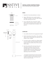
Start & Stop Push Button Station
To operate the pulper:
1. Ensure the drain valve is closed.
2. Ensure that the pulper and extractor
lids are closed
3. Ensure the “Empty/Run” selector switch
is in the “Run Position”
4. Flip the locking lever to release the
red stop button. The pulper will pre-
fill with water.
5. When the pulper is pre-filled, the
green button will illuminate.
6. Press the green button to start the
Pulper.
The Pushbutton Station may be located under the
table, on the wall or if specified may be
installed into the control panel door.

START UP CHECK OUT
Voltage Check
Measure the voltage of the incoming power and confirm that it matches the
voltage on the placard on the inside of the control panel door
Air Bubbles / Water Level Control
The water level control system functions by pumping air from the control
panel into the bottom of the pulper tank. As the water level increases, the
pressure in this airline increases proportionally. The pressure switch
monitors this airline pressure and turns the fresh water fill valve on when
the water level is low. At start up, it is good practice to check the
inside of the tank to make sure that there is a flow of air bubbles into the
tank. The air enters the tank through the drainpipe before the drain valve.
The proper adjustment of the water level
control system must be made before the unit
can operate properly. The photo shows the
cutting mechanism of the Super 60. The
level indicated by the line, about 1 inch
above the cutting mechanism, is the level
to which the pulper should fill before
starting the unit. The pressure control
switch should be adjusted, such that, when
the pulper stops filling, the water level
is within one-quarter inch of this line.
The lid switches must be functioning and the lids closed for the water level system
to operate. If you cannot get the system to start filling refer to the lid switch
section for probable cause.
The photo shows the pressure switch
located in the control panel. The
adjusting screw on the pressure switch is
rotated counter-clockwise to raise the
water level set point, and vice versa.
One-quarter turn of this adjustment screw
will change the level set point by
approximately one inch. When the pulper
fills to the pre-set water level, the
green start push button will illuminate,
indicating that the pre fill level has
been reached and the pulper is ready.

Motor Rotation Direction
When operating 3 phase motors, it is possible for the motors to turn in the
wrong direction when starting up the machine. The close coupled pulper has 3
motors, each of which needs to have the direction of rotation confirmed.
1. The pulper drive motor should turn counter clockwise as viewed
from inside the pulping tank.
2. The auger in the extractor drive should turn clockwise, as viewed
from above. If the extractor drive is attempting to turn
backwards, it will likely stall and cause an overload to trip
instead of actually turning backwards.
3. To check the direction of rotation of the return pump, you must
remove the top panel from the shrouded area between the pulper and
the extractor. (Just below the extractor access door.) The return
pump sits vertically within this shrouded area, with the motor fan
facing upward. The proper direction of rotation is counter-
clockwise, as viewing the motor fan from above.
Amperage Draw of Motors
When the pulper is operating, the amperage draw of each of the motors goes a
long way in telling whether the unit is installed and operating correctly.
The amperage of each motor should be checked below each of the motor overload
relays in the main control panel. The following chart shows the amperage
readings that should be expected when the pulper is operating on water only.
These readings should be checked before waste is fed into the pulper.
Motor w/ 230-Volt Supply w/ 460 Volt Supply
Pulper Drive 10 amps, (+/- 1 amp) 5 amps, (+/- ½ amp)
Extractor Drive 3 amps, (+/- 1 amp) 1 ½ amps, (+/- ½ amp)
Return Pump Drive 7 amps, (+/- 1 amp) 3 ½ amps, (+/- ½ amp)

Lid / Limit sensors
There are (3) types of sensors on the close-coupled pulper.
1. Extractor Chute. (Magnetic proximity sensor.)
This prevents the extractor from operating
with the lid on the chute open as this is
potentially dangerous should someone reach
into the head area. It is mounted on the
side of the chute and interfaces with a
magnet on the lid.
2. Hinged lid switch.
(Inductive proximity sensor.)
This sensor is mounted inside the latch
keeper, up from the bottom. The top of the
sensor will see the latch tang when placed
inside the keeper. The sensing range is very
small (3mm). If in need of adjustment care
must be taken not to raise the sensor too
high or the latch will come in contact with
the sensor. If this should happen and it is
damaged it will fail and require replacing.
(Refer to the exploded view section for
further clarification if needed.)
3. UDT lid switch.
(Magnetic inductive proximity sensor.)
The UDT (Under Dish Table) model has a
sensor mounted inside a ½” pipe. The sensor
is inside the pulper and will detect the
presence of the lid as it has a thin magnet
located in between two walls of stainless.
This sensor operates on 24-volts and extreme
care should be taken not
to apply 120 volts
to it. This will burn out the sensor and it
will require replacing.

CHEMICAL PUMP
The system comes supplied with a chemical
additive pump. This is for reducing odors
and adding disinfectants to the return
water to be circulated throughout the
system. The pump is easily adjusted
depending on the needs of the system and
for regulating the concentration
dependant on the recommendations of the
chemical manufacture. Simply turn the
adjusting ring. When using SOMAT’s Neutro
Plus the dial should be placed on setting
2 or 3.
Overdosing of the chemicals may cause
excess foam and bubbles in the water that
may interfere with the water level
control.
The pump is wired into the electrical
system and will operate whenever the
system is operating. There is an
additional manual switch to turn off the
pump should the user not wish to inject
any chemicals.
Extractor Overflow
The overflow port on the extractor should not come into play during normal
operations. The return pump is sized to have the capability to return more
water from the extractor shell than the pulper is capable of delivering to
it. Consequently, the water level in the extractor should be very low, and
below the elevation of the extractor overflow. The extractor overflow should
allow the release of water only during the “Empty Mode.” In the “empty
mode,” the extractor rinse system is energized, adding approximately 10
gallons per minute of hot water to the system. The extractor overflow is
needed only to allow the discharge, to drain, of this volume of water. If
water is flowing down the extractor overflow during normal operation, contact
the Somat factory.

System Overflow
One of the means in which the system
accomplishes weight and volume reduction,
is by removing from the waste, an amount of
“free-water” that foodservice waste
typically contains. Therefore, the system
is designed to divert this volume of
“system overflow” to waste in the pulper
drain line. Typically, the Somat system
will divert 1 to 4 gallons per minute to
the drain, as “overflow.” The rate of
overflow can be adjusted to match the needs
of your particular waste stream. This
adjustment is made with the stainless steel
“overflow control assembly” that is located
under the drive shroud next the pulper
drive motor. Upon system start-up, this adjustment should be made to
minimize the system’s use of fresh water. Most applications will operate
successfully with a setting of “2”, which is the factory setting If the waste
stream has an abnormally high volume of “mushy” food wastes, (mashed
potatoes, custards, etc.) the overflow rate may have to be increased.
Conversely, if the waste stream contains only disposable plastics and paper,
the overflow rate may reduce to “1.”
Refer to the photo for adjusting the overflow. The number is roughly
the volume of overflow in gallons per minute. If the setting needs to be
changed, simply loosen the four flange bolts and change the setting. If the
desired setting is to “3” or “4”, one of the flange bolts will have to be
removed to allow the tang to pass. When securing the tang, by tightening the
flange bolts, ensure that the tang is touching the side of the bolt, to
assure proper alignment. The setting number must be visible in the center of
the round hole for the assembly to function properly. When tightening the
hardware, be sure to tighten all four bolts evenly to assure equal pressure
around the plates, which prevents leakage.

PART NUMBERS AND VIEWS
SUPER 60 PULPER ASSEMBLY PARTS LIST
DESCRIPTION PART NO. QTY.
CUTTING MECHANISM (See Cutting Mechanism Section) 1
SEAL, MECHANICAL 54306 1*
MOTOR, 6 HP, TEFC 41660 1
Attaching Parts
Screw, Hex Head, 3/8"-16 X 1" Lg., S/S 4
Washer, Lock, 3/8" Split, S/S 4
VIBRATION ISOLATOR, Rubber 16200 4*
Attaching Parts
Screw, Hex Head, 3/8"-16 X 1" Lg., S/S 4
Washer, Lock, 3/8" Split, S/S 4
LID LATCH 35100 1
LID HANDLE 35220 1
LID GASKET 53410 1
LID STOP 84770 1
LIMIT SWITCH, Magnetic Proximity 54999-1 1
MAGNET 55007 1*
TRAY ONLY
Curtain 23011 1
Tray Gasket 33915 1
* Recommended Spare Parts
SS - Stainless Steel

SUPER 60 PIPING COMPONENTS PARTS LIST
DESCRIPTION PART NO. QTY.
FRESH WATER ASSEMBLY
Backflow Preventor, 1/2" * 11310 1*
Shock Arrestor, 1/2" 11303 1
Solenoid Valve, 1/2" * 64710-2 1*
DRAIN ASSEMBLY
Drain Valve, 2" 64840 1
WATER LEVEL CONTROL
Snubber * 59998 1*
Diaphragm Check Valve * order by description 1*
* Recommended Spare Parts
SS - Stainless Steel
SP-60 Cutting Mechanism
Security
Ring
Rotating
Blade
Impeller
Pumping
Vanes
Stationary Blade

SUPER 60 CUTTING AND PUMPING MECHANISM PARTS LIST
DESCRIPTION PART NO. QTY.
Rotating Blade 80960 1
Attaching Parts
Screw, Hex Head, 3/8"-24 X 1" Lg., S/S 2
Security Ring 87473 1
Attaching Parts
Screw, Hex Head, 3/8"-24 X 1/2" Lg., S/S 3
Washer, Flat, 3/8", S/S 3
Washer, Lock, 3/8" Split, S/S 3
Stationary Blade* 80988 3*
Attaching Parts
Screw*, Flat Head, 1/4"-20 X 1" Lg., S/S 6*
Nut*, Self Locking, 1/4"-20, S/S 6*
Impeller 86600-1 1
Attaching Parts:
Screw, Hex Head, 3/8"-16 X 3/4" Lg., S/S 1
Washer, Lock, 3/8" Split, S/S 1
Washer*, Flat, 3/8" Special, S/S 89201 1*
Key* 1/4" x 1/4" x 1" 1*
*Recommended Spare Parts

Remote units only
There are a few fundamental differences between the close couple units.
Electrical
1. The control power comes from the extractor panel; this panel
must be on for the system to work.
2. Interconnecting wires must be connected to correct terminals
(dash lines on FE print).
Plumbing
1. The elimination of the overflow assembly at the pulper. Balance of
the system is done in a normal Somat fashion (at the extractor).
On one on one units the throttling valve will be
located near the extractor in the return line adjust valve while
monitoring amps of the return pump motor.
On multiple units the throttling valve will be located near pulpers in
the return line adjust to obtain good trough flow and the desired
overflow at extractor.
(Special attention to not over amping motors)
Pressure switch
These units will have a dual switch in them. The left side is for
setting the “flood” level, this is controlling the operation of the
MOV stopping water flow in the return line if pulper is to full.
The right side is your normal prefill/operating water level setting
(approx 1” above security ring).
/