FORM: QM1110M
Rev. 1, November 2013
Page 1 of 12
Munters Corporation
4215 Legion Dr. Mason, MI 48854-1036 USA
Ph: +1 517 676-7070 Fax: +1 517 676-7078
www.munters.us
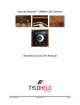
BI28M, BI28M-01, BI48M, BI48-01
BI28/BI48 Inlet
Bottom View
Top View
To Actuator / Winch

FORM: QM1110M
Rev. 1, November 2013
Page 2 of 12
Munters Corporation
4215 Legion Dr. Mason, MI 48854-1036 USA
Ph: +1 517 676-7070 Fax: +1 517 676-7078
www.munters.us
To achieve maximum performance and insure a long life from your Munters product it is essential
that it be installed and maintained properly. Please read all instructions carefully before
beginning installation.
Section
USER'S MANUAL and INSTALLATION GUIDE
TABLE OF CONTENTS
THANK YOU
PLEASE NOTE
Parts list ........................................................................................................................... 3
Framing ............................................................................................................................ 4
BIxxM Installation ............................................................................................................ 4 - 7
Latch Kit Operation .......................................................................................................... 8
Cabling ............................................................................................................................ 9 - 10
Performance Data ........................................................................................................... 11
Exploded View ................................................................................................................. 12
Thank you for purchasing a BI28/BI48 Ceiling Inlet from Munters. Our equipment is designed
to be the highest performing, highest quality equipment you can buy. With the proper
installation and maintenance it will provide many years of service.
WARRANTY
For Warranty claims information see the "Warranty Claims and Return Policy" form QM1021
available from the Munters Corporation offi ce at +1-800-227-2376 or by e-mail at
aghort.info@munters.com.
Conditions and Limitations:
• Products and Systems involved in a warranty claim under the “Warranty Claims and Return
Policy” shall have been properly installed, maintained and operated under competent
supervision, according to the instructions provided by Munters Corporation.
• Malfunction or failure resulting from misuse, abuse, negligence, alteration, accident or lack
of proper installation or maintenance shall not be considered a defect under the Warranty.

FORM: QM1110M
Rev. 1, November 2013
Page 3 of 12
Munters Corporation
4215 Legion Dr. Mason, MI 48854-1036 USA
Ph: +1 517 676-7070 Fax: +1 517 676-7078
www.munters.us
Each BI28M/BI48M includes:
1 – Plastic Frame with 2 doors attached
1 – Insulation Stop, 304,8 mm tall
1 – Fiberglass Rod (BI48M) only
1 – Hardware package as follows:
HP1240 for BI28M
[A]....8 – #9- 15 x 38,1 mm Hex Head Screw
[B]....1 – 4,7 mm Dia. Cable Clamp
HP1248 for BI48M
[A]....12 – #9 - 15 x 38,1 mm Hex Head Screw
[B]....1 – 4,7 mm Dia. Cable Clamp
[C]....4 – 6,3 mm Dia. Retainer Clips
Before beginning installation, check the overall condition of the equipment. Remove packing
materials, and examine all components for signs of shipping damage. Any shipping damage is the
customer's responsibility and should be reported immediately to your freight carrier.
UNPACKING THE EQUIPMENT
[A]
[B]
[C]
15,3 mm
106,3 mm
A
700 mm
DIMENSIONS
End View
Side View
Inlet A
BI28 798,5 mm
BI48 1331,9 mm

FORM: QM1110M
Rev. 1, November 2013
Page 4 of 12
Munters Corporation
4215 Legion Dr. Mason, MI 48854-1036 USA
Ph: +1 517 676-7070 Fax: +1 517 676-7078
www.munters.us
Step 1
Construct a framed opening in ceiling according
to Chart A and fasten to trusses or bracing
between trusses. Trim out framing with ‘J’-trim
if a metal ceiling is used. See Figure 1A and
1B. If inlet is being installed in a house with
a Tri-Ply ceiling, construct frame as shown in
Figure 1C.
Step 2
The hardware should already be installed as
shown in Figure 2. The Lift Lines should be
turned towards the actuator and the Eye Bolt
will be away from the actuator.
50 - 100 mm Framing
50 - 100 mm Framing
To Actuator
Figure 1A
Figure 2
See Chart A
See Chart A
Figure 1C
50 - 100 mm Framing
Metal Ceiling
Figure 1B
If installing inlets near heaters, it is
recommended to install the BI28/BI48
inlet at a location far enough from heaters
that will give a maximum temperature of
65.5°C. This should be approximately
610 - 915 mm from the heater.
IMPORTANT NOTE
Eye Bolt
Inlet Width Length
BI28 647,7 mm 647,7 mm
BI48 647,7 mm 1181,1 mm
Chart A

FORM: QM1110M
Rev. 1, November 2013
Page 5 of 12
Munters Corporation
4215 Legion Dr. Mason, MI 48854-1036 USA
Ph: +1 517 676-7070 Fax: +1 517 676-7078
www.munters.us
Step 3A
For the BI28, install the provided insulation stop into
the framed opening as shown using screws or staples
(not Provided). See Figure 3A.
Step 3B
For the BI48, fi nd the center of the long side of the
framing and start installing the insulation stop 38,1 mm
from the center, so that the insulation stop overlaps
the center of the opening. When the insulation stop
is completely installed the 2 ends of the stop should
overlap by 76,2 mm and the center of the overlap
should be at the center of the long side of the framing.
Use screws or staples (not provided) to fasten the
insulation stop in place. See Figure 3B and 3A.
Figure 3A
Insulation Stop
Insulation Stop
Inlet Frame
Long side of frame
Center
76,2 mm
38,1 mm
Figure 3B

FORM: QM1110M
Rev. 1, November 2013
Page 6 of 12
Munters Corporation
4215 Legion Dr. Mason, MI 48854-1036 USA
Ph: +1 517 676-7070 Fax: +1 517 676-7078
www.munters.us
Step 3C
At the middle of the long side of the insulation
stop,12,7 mm down from the top, drill or punch a 6,35
mm dia. hole on each side of the insulation stop. See
Figure 3C.
Step 3D
Install (1) Retaining Clip [C] on each end of the
fi berglass rod. The Retaining Clip should be 38,1 mm
from the end of the rod. Then insert the end of the
rod through the new hole in the insulation stop from
the inside out. Insert the other end of the rod through
the hole in the other side of the insulation stop. Install
the remaining Retaining Clip [C] on each end of the
fi berglass rod, so that the insulation stop is between 2
of the clips. See Figure 3D.
Figure 3C
Insulation Stop
Insulation Stop
Long side of
frame
Rod
Figure 3D
Retaining Clip [C]
Insulation Stop
6,35 dia. hole
6,35 dia. hole
12,7
mm

FORM: QM1110M
Rev. 1, November 2013
Page 7 of 12
Munters Corporation
4215 Legion Dr. Mason, MI 48854-1036 USA
Ph: +1 517 676-7070 Fax: +1 517 676-7078
www.munters.us
Step 4
Apply bead of caulk around top of inlet as shown in
Figure 4A. Position inlet into the framed opening and
attach inlet to framing using (8) Hex Head Screws
[A] provided. See Figure 4B. Be careful not to over
tighten as this may pull the frame out of shape.
Step 5
To ensure an airtight fi t, caulk around outside of
framing and inlet.
Step 6
Proceed to routing the main actuator cable or rod
through the holes in the inlet frame. It is required to
utilize a spring or weight on the actuator cable end
opposite the actuator. Once the cable is routed and
the actuator is in the open position, begin connecting
the lift lines from each inlet door to the actuator cable
using Cable Clamp [B] provided. See Figure 5.
Step 7
After lift lines for all inlets are connected and doors
are adjusted as needed, caulk the hole in the door for
the lift line, to prevent air leaks. See Figure 5.
Inlet Door
Cable Clamp [B]
Lift Line
Lift Line Guide
Azuma Bolt and Nut
Latch
Inlet Frame
Rod or cable by other
To Actuator
Figure 5
Figure 4B
Insulation Stop
Hex Head Screw [A]
50,8 mm
Framing
Inlet Frame
Figure 4A
Inlet Frame
Bead of Caulk
Eye Bolt
Hole for Lift Line

FORM: QM1110M
Rev. 1, November 2013
Page 8 of 12
Munters Corporation
4215 Legion Dr. Mason, MI 48854-1036 USA
Ph: +1 517 676-7070 Fax: +1 517 676-7078
www.munters.us
Step 8
Latch is preinstalled near center of door. Rotate
latch upward to unlock and downward to lock.
When inlet is in normal operation, be sure latch
is in up position so it does not interfere with
door closing. See Figure 6A and 6B.
Figure 6A
Latch Shown in Open Position
Figure 6B
Latch Shown in Closed Position
Latch Base
Latch Arm
Inlet Door
Inlet Frame

FORM: QM1110M
Rev. 1, November 2013
Page 9 of 12
Munters Corporation
4215 Legion Dr. Mason, MI 48854-1036 USA
Ph: +1 517 676-7070 Fax: +1 517 676-7078
www.munters.us
Step 9
Attach pulleys in line with the main rod or cable running
through each BI28/BI48. See Figure 7A and 7B.
Figure 7A
AC1264 Single Pulley
Bracket. Provide adequate
support.
Ceiling
Building Wall
WINCH/ ACTUATOR ENDSPRING END
AC1039 Cable Clamps.
Thread cable through loop
at end of spring and fasten
with (2) cable clamps.
AC1264 Single Pulley Bracket.
Recess pulley into ceiling in
order to keep cable in line with
rod.
Building Wall
Ceiling
AC1195 Baffl e return spring
Fasten spring into stud with lag
screw or bolt and nut.
Truss
AC1287 or
AC1286 Cable
SPRING TENSION:
with baffl e fully closed and cable pulled tight,
stretch spring 30cm - 35cm and fasten.
Figure 7B

FORM: QM1110M
Rev. 1, November 2013
Page 10 of 12
Munters Corporation
4215 Legion Dr. Mason, MI 48854-1036 USA
Ph: +1 517 676-7070 Fax: +1 517 676-7078
www.munters.us
Step 10
On each end of the run of BI28/BI48 inlets run a cable
through the pulleys to the winch or actuator on one end
and to the weights or return spring on the other end.
See Figure 7A, 7B and 8.
Step 11
With the winch or actuator at its fully closed position, check and readjust
each BI28/BI48 door tightly closed. Use winch or actuator to open and close
inlets a few times to make sure the doors open and close smoothly.
Figure 8
To Weights or
Return Spring
Winch or Acruator

FORM: QM1110M
Rev. 1, November 2013
Page 11 of 12
Munters Corporation
4215 Legion Dr. Mason, MI 48854-1036 USA
Ph: +1 517 676-7070 Fax: +1 517 676-7078
www.munters.us
PERFORMANCE DATA
BI28M, BI28M-01
BI48M, BI48M-01
0
2000
4000
6000
8000
10000
12000
14000
0.00 10.00 20.00 30.00
40.00 50.00 60.00 70.00
Static Pressure (Pascal)
Airflow (m³h)
Door Open
at 76.2mm
Door Open
at 101.6mm
Door Open
at 152.4mm
Door Open
at 228.6mm
(Fully Open)
0
1000
2000
3000
4000
5000
6000
7000
0.00 10.00 20.00 30.00 40.00 50.00 60.00
Static Pressure (Pascal)
Airflow (m³h)
Door Open
at 25.4mm
Door Open
at 76.2mm
Door Open
at 152.4mm
Door Open
at 228.6mm
(Fully Open)

FORM: QM1110M
Rev. 1, November 2013
Page 12 of 12
Munters Corporation
4215 Legion Dr. Mason, MI 48854-1036 USA
Ph: +1 517 676-7070 Fax: +1 517 676-7078
www.munters.us
BI28 & BI48 Inlet
Catalog Number
Item BI28 BI48 Part Name/Description
Qty
1 AC2635 AC2646 Inlet Door, Black Plastic 2
AC2635-01 AC2646-01 Inlet Door, w/Insulation, Black, Plastic 2
2 AC2630 AC2641 Inlet Frame, Black Plastic 1
3 AC2640 AC2640 Lift Line Guide Insert, BI28/BI48, Black Plastic 2
4 AC1039 AC1039 4,76 mm Dia. Cable Clamp 1
5 AC0212 AC0212 Azuma Nut Only, Wing type, Blue Plastic 2
6 AC0211 AC0211 Azuma Bolt only, Split type, Blue Plastic 2
7 AC1009 ---
1
⁄8" x 36"L. Braided Lift Line; White 2
--- AC1014
1
⁄8” x 66”L. Braided Lift Line; White 2
8 KS2755 KS2755 6,35 mm - 20 x 50,8 mm L. Closed Eye Bolt, Stainless Steel 1
9 KN0702 KN0702 6,35 mm - 20 Hex Serrated Flange Nut, Stainless Steel 1
10 AC2645 AC2645 BI28/BI48 Inlet Door Hinge Pin, Stainless Steel 2
/