Page is loading ...

Trademarks
CTS is a registered trademark of Connection Technology
Systems Inc. Contents subject to revision without prior notice.
All other trademarks remain the property of their owners.
Copyright Statement
Copyright Connection Technology Systems Inc.
This publication may not be reproduced as a whole or in part, in
any way whatsoever unless prior consent has been obtained from
Connection Technology Systems Inc.
FCC Warning
The MCT-3512 Series converters have been tested and found to
comply with the limits for a Class A digital device, pursuant to Part
15 of the FCC Rules. These standards are designed to provide
reasonable protection against harmful interference when these
devices are operated in a commercial environment. These
devices generate, use, and can radiate radio frequency energy
and may cause harmful interference to radio communications
unless installed in accordance with this User’s Guide. Operation of
these devices in a residential area is likely to cause harmful
interference which will make the user responsible for the
appropriate remedial action at his / her own expense.
CE Mark Warning
These are Class A products. In a domestic environment these
products may cause radio interference in which case the user will
need to consider adequate preventative methods.
1. Checklist
The package should contain the following items:
-
MCT-3512 Converter
-
AC-DC Power Adapter
-
User’s Guide
Please notify your sales representative immediately if any items
are missing or damaged.
2. Overview
The MCT-3512 series media converter converts traditional
twisted-pair RJ-45 cable into various fiber media including
multi-mode, single-mode, SC connector, bi-directional WDM, or a
SFP slot for pluggable fiber transceiver, extending transmission
distance for the deployment to the household, apartment or campus.
MCT-3512 series media converter is fully compliant with IEEE 802.3,
802.3u, 802.3ab & 802.3z standards.
Besides, it is equipped with some switching features including store
and forward. Operation status can be locally monitored through a
set of Diagnostic LED located in the front panel.
Major Features:
-
Auto-Negotiation in TP port
-
MDI/MDIX Auto-Crossover supported
-
Support Link Alarm
-
Support Jumbo Frame 9K bytes (under 10,100,1000Mbps)
-
Store and Forward Switching Mechanism
-
Support Auto & Force mode configuration
-
OAM
3. Installation
-
Attach fiber cable from the MCT-3512 to the fiber network. The
fiber connections must be matched – transmit socket to
receive socket.
-
Attach a UTP cable from the 10/100/1000BASE-T network to
the RJ-45 port on the MCT-3512.
-
Connect the power adapter to the MCT-3512 and check that
the PWR/STA LED lights up. The TP and F/O LEDs will light
up when all the cable connections are satisfactory.
Figure 1. MCT-3512 Dual Fiber Front Panel
Figure 2. MCT-3512 WDM & SFP Front Panel
Figure 3. MCT-3512 Converter Rear Panel
Figure 4. MCT-3512 Converter Side Panel
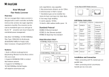
4. DIP SWITCH Setting
The default settings for PIN 1 through 6 are ON. The PIN 7 & 8 are
OFF.
Pin NO.
Function
OFF
ON
1
TP Auto-Negotiation
Disable
Enable
2
Manual TP speed
10M
100M
3
Manual TP speed
N/A
1000M
4
Fiber Speed
Manual
Auto-Sensing
5
Fiber Manual Speed
100M
1000M
6
F/O mode
Force
Auto
7
Link Alarm
Disable
Enable
8
Config from DIP/Soft
Soft
DIP
NOTE:
1. Before changing TP speed, please make sure PIN 1 is set
to OFF.
2. When TP speed is set to 10M or 100M manually, PIN 3 needs
to be turned OFF.
3. Under 1000Mbps, it supports full-duplex mode only.
4. PIN 4 & 5 are for dual rate model (MCT-3512-DR) only.

5. LED Description
6. Technical Specifications
Standards:
IEEE 802.3, 802.3u,
802.3ab,802.3ah, 802.3z
Interface:
1 X RJ-45 connector
1 X F/O port or SFP Slot
LED:
Power/Status, FDX, Speed,
F/O, TP
Power:
I/P AC 100-240V
O/P DC 3.3V
Power Consumption:
2.5W
Weight:
0.1Kg
Dimensions:
51mm(W)X74mm(D)X20mm(H)
Temperature:
Operating: 0
o
~50
o
C
Storage: -20
o
~60
o
C
Humidity:
5%~90% RH
Certification:
FCC/CE Class A
TP
EIA/TIA-568 CAT 5e, 1000M
Fiber
50/125, 62.5/125um multi-mode fiber
9/125, 10/125um single-mode fiber
Fiber Transceiver Information
Dual Rate
2 Wave-Length WDM
TYPE
W2A(SM-10)
W2B(SM-10)
Connector Type
SC
SC
Wavelength
1310/1550nm
1550/1310nm
Typical Distance
10 Km
10 Km
Min TX PWR
-10.0dBm
-10.0dBm
Max TX PWR
-3.0dBm
-3.0dBm
Sensitivity
-20.0dBm
-20.0dBm
Link Budget
10.0dB
10.0dB
1000M
Multi-Mode/Single-Mode
TYPE
BTFC
BTFC
(SM-10)
BTFC
(SM-20)
BTFC
(SM-30)
BTFC
(SM-50)
BTFC
(SM-80)
Connector
Type
SC
SC
SC
SC
SC
SC
Wavelength
850nm
1310nm
1310nm
1310nm
1550nm
1550nm
Typical
Distance
550m
10 Km
20 Km
30 Km
50 Km
80 Km
Min TX PWR
-9.5dBm
-9.5dBm
-5.0dBm
-5.0dBm
-5.0dBm
0dBm
Max TX
PWR
-4.0dBm
-3.0dBm
3.0dBm
3.0dBm
3.0dBm
5.0dBm
Sensitivity
-18.0dBm
-20.0dBm
-24.0dBm
-24.0dBm
-24.0dBm
-24.0dBm
Link Budget
8.5dB
10.5dB
19.0dB
19.0dB
19.0dB
24.0dB
2 Wave-Length WDM
TYPE
W2A
(SM-10)
W2B
(SM-10)
W2A
(SM-20)
W2B
(SM-20)
W2A
(SM-40)
W2B
(SM-40)
Connector
Type
SC
SC
SC
SC
SC
SC
TX
Wavelength
1310nm
1550nm
1310nm
1550nm
1310nm
1550nm
RX
Wavelength
1550nm
1310nm
1550nm
1310nm
1550nm
1310nm
Typical
Distance
10 Km
10 Km
20 Km
20 Km
40 Km
40 Km
Min TX
PWR
-10.0dBm
-9.0dBm
-7.0dBm
-7.0dBm
-3.0dBm
-3.0dBm
Max TX
PWR
-3.0dBm
-3.0dBm
0 dBm
0 dBm
2.0dBm
2.0dBm
Sensitivity
-22.0dBm
-22.0dBm
-23.0dBm
-23.0dBm
-22.0dBm
-22.0dBm
Link Budget
12.0dB
13.0dB
16.0dB
16.0dB
19.0dB
19.0dB
NOTE: Specifications may change without prior notice.
MCT-3512 SERIES
10/100/1000BASE-T to
1000BASE-X or
100/1000BASE-X
Managed Media Converter
User’s Guide
Version 0.90
Contact Information
Connection Technology Systems INC (CTS)
18F-6, No.79, Sec.1, Xintai 5th Rd., Xizhi Dist.,
New Taipei City 221, TAIWAN, R.O.C.
TEL: +886 2 26989661 FAX: +886 2 26989662
E-Mail: info@ctsystem.com
LED
Color
Function
PWR/STA
Off
Power is not ready.
Green
Lit solid when power is available, the
Local/Remote TP/Fiber port is link up and
OAM is link up. When Blinking fast, the result
of Loopback test is successful.
Orange
Lit solid when power is being booted up, or
Local/Remote TP/Fiber port is link down or
OAM is loss link. When blinking fast, the result
of Loopback test is fail. When blinking slow,
the Firmware version of the module does not
match with the Rack’s
Green &
Orange
Blinking
When green & orange blinking fast in turn, the
Loopback test is being processing. When
green & orange blinking slow in turn, the
firmware upgrade is being processing.
TP
Off
The port is link down.
Green
Lit when TP cable connection with remote
device is good. Blink when TP traffic is
present.
F/O
Off
The port is link down.
Green
Lit when Fiber cable connection at 100M with
remote device is good. Blink when F/O traffic is
present. (For dual rate model only)
Orange
Lit when Fiber cable connection at 1000M with
remote device is good. Blink when F/O traffic is
present.
FDX
Green
Lit when TP works in Full-Duplex.
Not-Lit when TP works in Half-Duplex.
SPD
Green
Lit when TP works in 10M.
Lit when TP works in 100M.
Orange
Lit when TP works in 1000M.
/