Page is loading ...

WH-4200 WELDING TORCH with
CA-4200 and CA-1500 CUTTING ATTACHMENTS
0558011297 05/2013
Instruction Manual

2
BE SURE THIS INFORMATION REACHES THE OPERATOR.
YOU CAN GET EXTRA COPIES THROUGH YOUR SUPPLIER.
SAVE THESE INSTRUCTIONS!
IMPORTANT SAFEGUARDS
When using Oxy-Fuel Gas Torches, basic safety precautions should always be followed:
Never use Acetylene gas at a pressure over 15 psig.a.
Never use damaged equipment.b.
Never use oil or grease on or around Oxygen equipment.c.
Never use Oxygen or fuel gas to blow dirt or dust o clothing or equipment.d.
Never light a torch with matches or a lighter. Always use a striker.e.
Always wear the proper welding goggles, gloves and clothing when operating Oxy-Acetylene equipment. f.
Pants should not have cus.
Do not carry lighters, matches or other ammable objects in pockets when welding or cutting.g.
Always be aware of others around you when using a torch.h.
Be careful not to let welding hoses come into contact with torch ame or sparks from cutting.i.
SAVE THESE INSTRUCTIONS.j.
This equipment will perform in conformity with the description thereof contained in this manual and accompa-
nying labels and/or inserts when installed, operated, maintained and repaired in accordance with the instruc-
tions provided. This equipment must be checked periodically. Malfunctioning or poorly maintained equipment
should not be used. Parts that are broken, missing, worn, distorted or contaminated should be replaced imme-
diately. Should such repair or replacement become necessary, the manufacturer recommends that a telephone
or written request for service advice be made to the Authorized Distributor from whom it was purchased.
This equipment or any of its parts should not be altered without the prior written approval of the manufacturer.
The user of this equipment shall have the sole responsibility for any malfunction which results from improper
use, faulty maintenance, damage, improper repair or alteration by anyone other than the manufacturer or a ser-
vice facility designated by the manufacturer.
These INSTRUCTIONS are for experienced operators. If you are not fully familiar with the prin-
ciples of operation and safe practices for gas welding and cutting equipment, we urge you to read
our booklet, “Precautions and Safe Practices for Gas Welding, Cutting, and Heating,” Form F-2035.
Do NOT permit untrained persons to install, operate, or maintain this equipment. Do NOT attempt
to install or operate this equipment until you have read and fully understand these instructions. If
you do not fully understand these instructions, contact your supplier for further information. Be
sure to read the Safety Precautions before installing or operating this equipment.
CAUTION
USER RESPONSIBILITY
READ AND UNDERSTAND INSTRUCTION MANUAL BEFORE INSTALLING
OR OPERATING. PROTECT YOURSELF AND OTHERS!

3
TITLE .......................................................................................................................................................... PAGE
ENGLISH ..................................................................................................................................................................................................... 1
SPANISH ...................................................................................................................................................................................................17
FRENCH ....................................................................................................................................................................................................29
TABLE OF CONTENTS

4
TABLE OF CONTENTS

5
SECTION 1 SAFETY PRECAUTIONS
These Safety Precautions are for your protection. They summarize
precautionary information from the references listed in Additional
Safety Information section. Before performing any installation or
operating procedures, be sure to read and follow the safety precau-
tions listed below as well as all other manuals, material safety data
sheets, labels, etc. Failure to observe Safety Precautions can result
in injury or death.
PROTECT YOURSELF AND OTHERS - Some weld-
ing, cutting and gouging processes are noisy and
require ear protection. Hot metal can cause skin
burns and heat rays may injure eyes. Training in
the proper use of the processes and equipment is
essential to prevent accidents. Also:
1. Always wear safety glasses with side shields in any
work area, even if welding helmets, face shields, or
goggles are also required.
2. Wear ameproof gauntlet type gloves, heavy long-sleeve shirt,
cuess trousers, high-topped shoes, and a welding helmet or cap
for hair protection, to protect against hot sparks and hot metal.
A ameproof apron may also be desirable as protection against
radiated heat and sparks.
3. Hot sparks or metal can lodge in rolled up sleeves, trousers cus,
or pockets. Sleeves and collars should be kept buttoned, and open
pockets eliminated from the front of clothing.
4. Protect other personnel from hot sparks with a suitable non-am-
mable partition or curtains.
5. Use goggles over safety glasses when chipping slag or grinding.
Chipped slag may be hot and can travel considerable distances.
Bystanders should also wear goggles over safety glasses.
FIRES AND EXPLOSIONS - Heat from a ame can act
as an ignition source. Hot slag or sparks can also
cause res or explosions. Therefore:
1. Remove all combustible materials well away from
the work area or completely cover the materials with a
protective non-ammable covering. Combustible ma-
terials include wood, cloth, sawdust, liquid and gas fuels, solvents,
paints and coatings, paper, etc.
2. Hot sparks or hot metal can fall through cracks or crevices in oors
or wall openings and cause a hidden smoldering re on the oor
below. Make certain that such openings are protected from hot
sparks and metal.
3. Do not weld, cut, or perform any other hot work on materials, con-
tainers, or piping until it has been completely cleaned so that no
substances on the material can produce ammable or toxic vapors.
Do not do hot work on closed containers. They may explode.
4. Have re extinguishing equipment handy for instant use, such as a
garden hose, a pail of water or sand, or portable re extinguisher.
Be sure you are trained in its use.
5. After completing operations, inspect the work area to be sure that
there are no hot sparks or hot metal which could cause a later re.
Use re watchers when necessary.
6. For additional information, refer to NFPA Standard 51B, “Fire Preven-
tion in Use of Cutting and Welding Processes”, which is available
from the National Fire Protection Association, Batterymarch Park,
Quincy, MA 02269.
FUMES AND GASES - Fumes and gases, particularly in conned
spaces, can cause discomfort or injury. Do not breathe fumes or
gases from welding or cutting, Therefore:
1. Always provide adequate ventilation in
the work area by natural or mechanical ventilation
means. Do not weld, cut, or gouge on materials
such as galvanized steel, stainless steel, copper,
zinc, lead, beryllium, or cadmium unless positive
mechanical ventilation is provided. Do not breathe fumes and
gases from these materials.
2. If you develop momentary eye, nose, or throat irritation while op-
erating, this is an indication that ventilation is not adequate. Stop
work at once and take necessary steps to improve ventilation in
the work area. Do not continue to operate if physical discomfort
persists.
3. Refer to ANSI/ASC Standard Z49.1 listed below for specic ventila-
tion recommendations.
EQUIPMENT MAINTENANCE - Faulty or improperly maintained
equipment, such as torches, hoses and regulators, can result in
poor work, but even more important, it can cause injury or death
through res. Therefore:
1. Always have qualied personnel perform the in-
stallation, troubleshooting, and maintenance work. Do not
operate or repair any equipment unless you are qualied
to do so.
2. Keep all oxy-fuel equipment free of grease or oil.
Grease, oil, and other similar combustible materials, when ignited,
can burn violently in the presence of oxygen.
3. Do not abuse any equipment or accessories. Keep equipment away
from heat and wet conditions, oil or grease, corrosive atmospheres
and inclement weather.
4. Keep all safety devices in position and in good repair.
5. Use equipment for its intended purpose. Do not modify it in any
manner.
GAS CYLINDER HANDLING - Gas cylinders, if mishandled, can rupture
or explode violently. Sudden rupture of a cylinder, valve or relief
device can injure or kill you. Therefore:
1. Use the proper gas for the process and use the
proper pressure reducing regulator designed to operate
from the compressed gas cylinder. Do not use adaptors to
mount the regulator on the cylinder. Maintain hoses and
ttings in good condition. Follow manufacturer’s operat-
ing instructions for mounting the regulator to the gas cylinder.
2. Always secure cylinders in an upright position by chain or strap to
suitable hand trucks, benches, walls, post, or racks. Never secure
cylinders to work tables or xtures where they may become part
of an electrical circuit.
3. When not in use, keep cylinder valves closed. Have the valve protec-
tion cap in place on top of the cylinder if no regulators is installed.
Secure and move cylinders by using suitable hand trucks. Avoid
rough handling of cylinders.
4. Locate cylinders away from heat, sparks, or ame of a welding,
cutting, or gouging operation. Never strike an arc on a cylinder.
5. For additional information, refer to CGA Standard P-1, “Precautions
for Safe Handling of Compressed Gases in Cylinders:, which is avail-
able from the Compressed Gas Association, 1235 Jeerson Davis
Highway, Arlington, VA 22202.
ADDITIONAL SAFETY INFORMATION - For more information on safe
practices for oxy-fuel welding and cutting equipment, ask your
distributor for a copy of “Precautions and Safe Practices for
Gas Welding, Cutting, and Heating”, Form 2035. Gas apparatus
safety guidelines are also available on video cassettes from
your distributor.
The following publications, which are available from the
American Welding Society, 550 N.W. LeJuene Road, Miami,
FL 33126, are recommended to you:
1. ANSI/AWS Z49.1 - “Safety in Welding and Cutting”.
2. AWS F4.1 - “Recommended Safe Practices for the
Preparation for Welding and Cutting of Containers and Piping
That Have Held Hazardous Substances”/
3. AWS SP - “Safe Practices” - Reprint, Welding Handbook.
Used to call attention to immediate hazards which,
if not avoided, will result in immediate, serious
personal injury or loss of life.
Used to call attention to potential hazards which
could result in personal injury or loss of life.
Used to call attention to hazards which could result
in minor personal injury.
This symbol appearing in this manual means At-
tention! Be Alert! Your safety is involved.

7
OPERATING INSTRUCTIONS
CONNECTING
1. Attach regulators to the oxygen and fuel gas cylinders. Follow
all instructions supplied with your regulators.
2. Attach oxygen and fuel gas hoses (see Note 1 in Operating
Data section on page 4 for recommended hose sizes) to the
regulators and to the torch handle, after making sure all metal
seating surfaces are clean. Tighten all connection nuts with
a wrench.
3. Using Welding or Heating Head: Remove welding head
connection nut from torch handle. Insert welding head into
handle using slight back and forth twisting motion as you
push. Slip connection nut over the head and hand-tighten
to handle.
Using Cutting Attachment: Set the welding head connec-
tion nut aside and insert the cutting attachment to the torch
handle in the same manner as the welding head. Remove
nozzle nut and insert cutting nozzle into the cutting at-
tachment head. Slip nut over the nozzle and tighten with a
wrench.
4. Check throttle valve packing nuts for tightness.
Flashbacks can cause serious burns.
Be sure gas ow is sucient for head or nozzle size.
Adjust regulators for proper psig pressures.
Adjust throttle valves properly.
Keep torch in good repair.
DO NOT throttle back gases to use large head or nozzle on thin
material.
ADJUSTING GAS PRESSURES
Fuel Gas: With oxygen valve closed, open the fuel gas valve on
the torch handle about one turn. Turn in the pressure-adjusting
screw on the fuel gas regulator until its delivery-pressure gauge
indicates the desired pressure (refer to operating tables starting
on page 5). Then immediately close the torch fuel gas valve.
Oxygen, Using Welding or Heating Head: Open the torch oxygen
valve at least 1-1/2 turns. Adjust oxygen pressure at the regulator
to the desired pressure (refer to Table 2, 3 or 4) and then close
the torch oxygen valve.
Oxygen, Using Cutting Attachment: Open the torch oxygen
valve WIDE and leave the preheat oxygen valve on the cutting at-
tachment closed. Depress the cutting oxygen valve lever on the
cutting attachment. Adjust the oxygen pressure at the regulator
to the desired pressure (refer to table 5, 6, 7 or 8). Shut o the
oxygen ow by releasing the cutting oxygen valve lever only.
SECTION 2 OPERATION
TESTING FOR LEAKS
Every welding and cutting outt should be thoroughly tested for
leaks after it is rst hooked up, and at regular intervals thereafter.
After all connections have been made, make sure both valves on
the torch handle are closed. Then turn in the regulator pressure-
adjusting screws clockwise until the oxygen delivery-pressure
gauge registers 50 psi, the fuel gas delivery-pressure gauge
registers 10 psi. Using Leak Test Solution suitable for oxygen
service, such as P/N 998771 (8oz. container), check for leaks at the
cylinder valves, the cylinder-to-regulator connections, the regu-
lator-to-hose connections, and the hose-to-torch connections. If
bubbling at any point indicates leakage, tighten the connection.
If this does not stop the leakage, close the appropriate cylinder
valve, open the torch valve to remove all pressure from the line,
and nally release the regulator pressure-adjusting screw by
turning it counterclockwise. Then break the leaky connections,
wipe metal seating surfaces with a clean, dry cloth, and examine
them for nicks and scratches. Remake the connection(s) and
retest. Do not try to light the torch until you are satised that
all connections are gas-tight.
LIGHTING & FLAME ADJUSTMENT
CAUTION: Use friction lighter for lighting torch. Do NOT use
a match. Use of a match can seriously burn your
hand.
Welding or Heating Head (Acetylene)
1. Open fuel gas valve about 1/2 turn and light the gas at the
tip.
2. Slowly close the fuel gas valve until the yellow ame just
starts to throw o smoke.
3. Open oxygen valve slowly until you have a neutral ame.
4. If harsher or soft ame is desired, readjust the two valves.
NOTE: When operating with a very soft ame, the welding
head will tend to heat up and transfer some of this
heat back to the torch handle. This may create some
discomfort to the operator.
Heating Head (Fuel Gases except Acetylene)
1. Crack fuel gas valve and light the gas at the tip.
2. Open fuel gas valve until ames start to leave end of tip.
3. Slowly open oxygen valve until ames are at their shortest
lengths.
4. If necessary, alternately open fuel gas and oxygen valves to
the desired ame size.
Cutting Attachment (Acetylene)
1. Open the acetylene valve on the torch handle about 1/2
turn, and light the gas at the nozzle.
2. Slowly close the acetylene throttle valve until the yellow
ame just starts to throw o black smoke.
3. Slowly open preheat oxygen valve on cutting attachment
until neutral ames are obtained.
4. Finally, open the cutting oxygen valve by depressing lever
and readjust the neutral ames by turning preheat oxygen
valve.
WARNING

8
The ame now has the proper strength for any cutting job. With
this ame, acetylene is being consumed economically and the
cutting attachment will be operating at best resistance to ash-
back. If greater preheat ame temperature is desired for faster
starts or piercing, open the cutting oxygen valve and adjust the
preheat oxygen valve until the ame inner cores shorten about
10 percent and become sharply pointed.
Cutting Attachment (Fuel Gases except Acetylene)
1. Crack the fuel gas valve and light the gas at the nozzle.
2. Open the fuel gas valve until ame starts to leave the end
of the nozzle.
3. Slowly open preheat oxygen valve on cutting attachment
until ame stabilizes.
4. Depress lever to open cutting oxygen valve and then adjust
preheat oxygen valve until preheat ames are at their short-
est length.
5. If larger or smaller preheat ames are desired, depress cut-
ting oxygen valve lever and alternately readjust fuel gas and
preheat oxygen valve to obtain the nal ame setting.
SHUTTING OFF
Close the fuel gas valve rst, then the oxygen valve whether you
are using a welding head or cutting attachment. However, if the
cutting attachment is to be relighted within a half-hour, you may
close the preheat oxygen valve on the attachment instead of the
oxygen valve on the torch handle.
If operations are to be stopped for a half-hour or more, you
should release all pressure from regulators. To do this, rst close
both cylinder valves. Then open the torch valves. Finally, back out
the regulator pressure-adjusting screws until they turn freely.
OPERATING PRECAUTIONS
Do not exceed 15 psig acetylene during operation.
Flow: There must be proper ow of gases for safe operation and
full performance. This requires the following three conditions:
(1) the regulators that determine the inlet pressure to the hoses
must be set to the correct pressure: (2) the hoses and their con-
nectors must have adequate capacity for the job (hoses that are
too long, too small or have connectors with small passageways
can cause problems); and (3) the throttle valves on the torch must
be adjusted with the procedure shown in these instructions.
Note: Items (1) and (2) can be checked by measuring the gas
pressures at the torch. Gauge adaptors are available for
this purpose.
Backre: Improper operation of the torch or cutting attachment
may cause the ame to go out with a loud 'pop'. (If you are weld-
ing, the ame will often reignite instantly.) Such a backre may
be caused by contact of tip or nozzle with the work, by spatter
from the work, by the use of incorrect gas pressure, or by leakage
at the cutting nozzle seats due to dirt or nicks on seats or to a
loose nozzle nut. After a backre, you can normally relight the
ames immediately. However, if backres occur repeatedly, shut
o the torch. Check the 'O'-ring seals between the welding head
or cutting attachment and the handle, and the nozzle seats (if
cutting). Readjust operating pressure and relight.
Flashback: Under certain circumstances, the ame may not
'pop' out (backre) but instead burn back inside the torch with
a shrill hissing or squeal. This is called a 'ashback'. A ashback
should never occur if (1) the equipment is in good condition;
(2) preheat ports on cutting nozzles or welding tips are cleaned
frequently; (3) operating pressures are correct; and (4) throttle
valves are adjusted properly. Should a ashback occur, IMMEDI-
ATELY shut o the torch. Allow it to cool o for at least a minute.
Then check your nozzle or tip, gas pressures, readjust regulators
if necessary, and relight the torch. If ashback recurs, send the
torch handle and welding head or cutting attachment to your
distributor for repair.
SECTION 2 OPERATION

9
IMPORTANT OPERATING NOTES
1. Pressures given in Tables 2 through 8 are measured at the
regulator using 25-ft. long hoses (1/4-in. I.D. up through size
No. 30 welding/heating head or for cutting up to 3-in. thick
steel; 3/8-in. I.D. for larger heads or cutting nozzles). If longer
hoses are required, only 3/8-in. I.D. hoses should be used
and pressure drop between regulator and torch should be
considered. Use test gauge adaptors to check for proper
pressure at torch if using long hose lengths, or if there are
doubts about the adequacy of gas ows. Do NOT use hose
line check valves when operating No. 55 and larger heads.
2. Head size number on each welding and heating head indi-
cates the rated acetylene ow capacity in cubic feet/hour
(cfh). For example, No. 55A requires about 55 cfh of acety-
lene at the given operating pressures. However, on heating
heads designed for other fuel gases, the size indicates the
approximate equivalent heating capacity in terms of acety-
lene ow. For example, note from Table 3 that No. 100A
and No. 100FG provide the same average heating output
(147,000 Bt/hr) but No. 100FG head really requires about 62
cfh of FG-2, 57 cfh of propane, or 147 cfh of natural gas.
For consumption purposes, the following are the oxygen
fuel gas ratios normally required for welding and heating:
1.1 to 1.5 cfh oxygen/1.0 cfh acetylene
3.2 to 3.6 cfh oxygen/1.0 cfh FG-2
3.5 to 4.5 cfh oxygen/1.0 cfh propane
1.7 to 2.0 cfh oxygen/1.0 cfh natural gas
3. Correct pressure and ow must be maintained for proper
operation of a welding or heating head. If a tip is "starved"
due to insucient ow of fuel gas, the tip may overheat and
cause backre or ashback.
An acetylene or a liqueed fuel gas (LFG) cylinder has a
limited capacity for delivering fuel to the tip; therefore, it is
extremely important to manifold 2 or more cylinder when
operating larger heads to assure adequate supply of fuel gas
to the tip. The rate of withdrawal depends on type of fuel
gas cylinder size, the contents remaining, and the outside
temperature. Tabulated below is the number of the more
commonly used cylinders recommended for manifolding
when using larger heads. If using other cylinders or gases,
check with your fuel gas supplier for recommended with-
drawal rate information.
4. The tables show average values based on typical condi-
tions. The type and quality of steel, its surface condition,
and purity of oxygen, etc., will always have a bearing on the
end results.
SECTION 2 OPERATION
Head Flowrate, Min. No. of Cylinders Required*
Size cfh WK Cyl (300 cf) WLT Cyl. (390 cf)
55 55 2 1
70 70 2 2
100 100 3 2
150 150 4 3
200 200 5 4
250 250 6 5
300 300 7 6
* Based on that max. hourly owrate should not exceed 1/7 of cylinder capacity at 70° F.
Example 1/7 (300 of WK cyl.) = 43 cfh max.
Head Flowrate, Min. No. of Flowrate, Min. No. of
Size cfh Cyl. Req’d* cfh Cyl. Req’d**
70 43 1 40 1
100 62 1 58 1
150 93 1 86 2
200 124 2 116 2
300 186 2 174 3
500 310 3 290 5
*Based on max. continuous withdrawal rate of 110 cfh for 104 lb. cylinder, 1/2 full @ 70o F.
**Based on max. continuous withdrawal rate of 65 cfh for 100 lb. cylinder, 1/2 full @ 70o F.
Withdrawal rate will increase with wind velocity and intermittent usage; reduce with lower temperature.
Propane (100 lb. of cyl.)FG-2 (104 lb. cyl.)

10
Table 2 - WH-4200 Acetylene Welding Heads (Single-Flame)
Size indicates approx. acetylene ow rate in cu. ft./hr. (cfh) at normal operating pressure.
See Important Operating Notes on page 4.
Table 3 - WH-4200 Multiame Heating Heads
Complete Pressure, Avg. Replacement Parts Accessory Tip
Head Assembly psig Heat Cleaning
Fuel No. of Output Mixer Tip Drill
Size Part No. Oxy. Gas Flames Btu/hr. Tip Throat Mixer Extension Size
For Oxy-Acetylene Use
55A 998089 7-9 7-9 7 81,000 998070 21K77 639965 19X42 (12") 59
70A 998090 7-9 7-9 7 102,000 998071 21K78 639966 19X42 (12") 56
100A 998091 10-12 10-12 8 147,000 998072 639993 639992 19X43 (15") 55
150A 998092 12-14 12-14 12 221,000 998073 639994 639992 19X44 (18") 55
For Oxy-Fuel Gas Use - FG-2, propane, natural gas, etc.
70FG 998093 16-20 7-10 7 104,000 998078 21K78 639966 19X42 (12") 54
100FG 998278 35-39 7-10 8 147,000 998079 998035 998034 19X43 (15") 48
150FG 998276 30-35 7-10 12 220,000 998036 639994 639992 19X44 (18") 48
See Important Operating Notes on page 4.
Table 4 - WH-4200 Rosebud Style Multiame Heating Heads
Complete Pressure, Avg. Replacement Parts (See Fig. 2) Accessory Tip
Head Assembly psig Heat Cleaning
Fuel No. of Output Tip Mixer Conn. Retain. Tip Extension Drill
Size Part No. Oxy. Gas Flames Btu/hr. Assy. Stem Throat Mixer Nut Ring Length P/N Size
For Oxy-Acetylene Use
15 O-A 998773 5-8 5-8 6 22,000 998795 998791 639693 639436 998580 13K02 — — 70
30 O-A 998774 5-8 5-8 6 44,000 998796 998791 639694 639437 998580 13K02 — — 62
30 O-A-JR 0558006160 5-8 5-8 6 44,000 ---------- ---------- 639694 639437 998580 13K02 — — 62
55 O-A 998775 7-9 7-9 9 81,000 998797 998792 21K77 639965 998580 13K02 12-in. 19X42 61
70 O-A 998776 7-9 7-9 9 103,000 998798 998792 21K78 639966 998580 13K02 12-in. 19X42 57
100 O-A 998777 13-16 8-10 13 147,000 998799 998793 639993 639992 639995 639709 15-in. 19X43 57
200 O-A 998778 19-22 11-14 16 294,000 998800 998794 998779 998780 639995 639970 18-in. 998790
54
For Oxy-Fuel Gas Use - FG-2, propane, natural gas, etc.
70 O-FG 999225 13-24 6-13 8 104,000 999224 998792 21K78 639966 998580 13K02 12-in. 19X42 49
100 O-FG 999228 18-31 8-15 8 148,000 999227 998793 998035 998034 639995 639970 15-in. 19X43 49
200 O-FG 999231 38-60 9-17 24 297,000 999230 998794 998045 22K39 639995 639970 18-in. 998790
52
See Important Operating Notes on Pg. 4.
Requires extension coupling 998838.
SECTION 2 OPERATION
Complete Replacement Parts
Head Assembly Pressure,psig Accessory Tip
Steel Cleaning
Thickness, Mixer Tip Drill
Size Part No. in. Oxy. Acet. Tip Throat Mixer Extension Size
1A 639438 to 32 ga. 639682 — 639885 — 78
2A 639439 32 - 25 ga. 639683 — 639885 — 72
4A 639440 25 ga. - 1/32 5-8 5-8 639684 — 639886 — 64
6A 639441 1/32 - 1/16 639685 — 639887 — 62
9A 639442 1/16 - 1/8 639686 17513 19484 — 55
12A 17268 1/8 - 3/16 17266 17513 17514 — 54
15A 639443 3/16 - 1/4 639687 639693 639436 — 53
30A 17263 1/4 - 3/8 17261 17262 639437 — 45
55A 998085 3/8 - 5/8 7-9 7-9 998060 21K77 639965 19X42(12") 33
70A 998086 5/8 - 1 998061 21K78 639966 19X42(12") 30
100A 998087 over 1 998062 639993 639992 19X43(15") 25

11
Nozzle Steel Pressure, psig Gas Consumption, ft
3
/hr Cleaning
Thickness, Drill Size
Size Part No. in. Oxygen Acetylene Oxygen Acetylene Preheat Cutting
Table 5 - 4202 Series Acetylene Cutting Nozzles (CA-4200)
Table 6 - 4217 Series Fuel Gas Two-Piece Cutting Nozzles
NOTE: Do NOT use with Acetylene.
Nozzle Sleeve Steel Pressure, psig Gas Consumption, ft
3/
hr Cleaning
Nozzle (Internal) (External) Thickness, Fuel Gas Fuel Gas Drill Size
Size P/N P/N in. Oxygen FG-2 Propane Nat.Gas Oxygen FG-2 Propane Nat.Gas Cutting•
1/4" 19485 19518 1/4" 30 4 6 7 70 8 12 30 68
1/2" 19486 19518 1/2" 35 4 7 8 120 9 14 32 60
1" 19487 19518 1" 40 4 8 9 180 10 15 35 53
2" 19488 19518 2" 45 5 9 10 250 11 16 40 50
4" 19489 19519 4" 40 4 8 10 370 12 18 45 43
6" 19490 19519 6" 50 5 12 13 520 14 20 50 39
8" 19491 19519 8" 50 6 15 16 610 16 22 55 35
•Usesoft-bristledbush(750F99)tocleanpreheatslotsofinternalnozzles.
SECTION 2 OPERATION
1/8" 638869 1/8 40 5 30-35 5-8 73 76
1/4" 16K08 1/4 40 5 40-45 8-10 73 68
1/2" 16K09 1/2 40 5 70-75 10-12 73 60
1-1/2" 16K10 3/4 40 5 90-100 12-14 69 55
1 55 6 120-125 14-16 69 55
1-1/2 70 6 160-170 16-18 69 55
4" 16K11 2 45 6 190-200 18-20 68 50
3 60 9 225-235 20-22 68 50
4 75 9 300-320 22-25 68 50
6" 16K12 6 70 9 450-470 30-32 64 43
10" 16K13 8 80 15 600-625 40-45 60 35
Nozzle Steel Pressure, psig Gas Consumption, ft
3
/hr Cleaning Drill Size
Thickness
Size Part No. in. mm Oxygen Acetylene Oxygen Acetylene Preheat Cutting
1502 Series (Medium Preheat)
1/4" 08Z67 1/4 6 25-30 5-8 35-45 6-8 69 68
1/2" 15Z17 1/2 13 35-40 65-75 8-10 66 60
1-1/2" 15Z18 3/4 19 35-40 120-135 14-16
1 25 40-45 5-8 130-140 14-16 65 53
2 50 30-35 185-210 16-20
4" 15Z19 3 75 40-45 6-9 205-255 16-20 61 46
4 100 45-50 235-285 19-22
8" 15Z20 6 150 35-45 395-460 20-25
8 200 55-65 8-10 545-625 30-35 57 39
Table 7 - 1502 Series Acetylene Cutting Nozzles (CA-1500)

12
Table 8 - 1567 Series - General Purpose Fuel Gas Two-Piece Cutting Nozzles (High Preheat)
Table 8A - 1564 Series One-Piece Cutting Nozzles FG-2 and MAPP Fuel Gases
Sleeve (External)
Nozzle Part No. Steel Gas Pressure, Gas Consumption, Cleaning
tfgispssenkcihT2-GF2-GFsaG .taNlanretnIelzzoN
3
/hr Drill Size
Size Part No. Propane mapp mapp in. mm. Oxygen Fuel Gas Oxygen FG-2
Nat. Gas Cutting
1567 Series (High Preheat)
1/8" 639614 1/8 3 20 - 40 5 - 10 20 - 25 79
1/4" 639615 1/4 6 45 - 65 5 - 10 20 - 25 69
1/2" 639616 639322 998277 998557 1/2 13 40 3 - 5 65 - 85 5 - 10 20 - 25 65
3/4" 639617 3/4 19 70 - 90 5 - 10 20 - 25 61
1" 639618 1 25 95 - 115 5 - 10 25 - 30 54
2" 639619 2 50 175 - 200 8 - 15 30 - 35 51
3" 639620 3 75 235 - 260 8 - 15 35 - 40 47
4" 998734 14Z39 114Z08 998561 4 100 300 - 335 10 - 15 35 - 40 46
8" 998735 6 150 40 450 - 480 10 - 15 40 - 45 39
14Z77 639755 998558 8 200 55 - 60 5 - 10 560 - 590
Use where high preheat intensity is desired.
Consumption of MAPP or propane is approximately the same as FG-2.
Use soft-bristled brush (750F99) to clean preheat slots of internal nozzles.
Heavy-duty sleeve (14Z96) available for use in place of 14Z77 sleeve.
SECTION 2 OPERATION
Metal
Thickness
in.
Tip
Size
in.
Part
Number
Gas Pressure
Cutting
Speed
Gas Consumption
Average
Kerf Width
Cutting Oxygen
psig
Preheat Oxygen
psig
Propylene
psig
ipm
Total Oxygen
cfh
Propylene
cfh
in.
39
Cutting Tips
1564 Series Propylene Tips
Hand or Machine Cutting Tips
Metal Thickness Tip Size
Part
Number
Number
Preheat
Holes
Cleaning
Preheat
Drill Size Cutting
in. mm in. in.
1/8-1/2 10-19 1/2 638983 8 67 60
3/4-1
1
/
2
19-50 1
1
/
2
638984 8 64 53
2-4 50-100 4 638985 8 62 46
4-8 100-200 8 638986 8 59 39
8-12 200-300 12 638987 8 56 31
Operating Data
Metal
Thickness
Tip
Size
Part
Number
Gas Pressure
Cutting
Speed
Gas Consumption
Average
Kerf WidthCutting Oxygen Preheat Oxygen Propylene Total Oxygen Propylene
in. in. psig psig psig ipm cfh cfh in.
1/4 1/2 638983 20-25 20-50 3-5 18-24 55-60 3-4 .050
1/2 1/2 638983 30-35 20-50 3-5 14-22 70-80 4-5 .065
3/4 1
1
/
2
638984 30-35 20-50 3-5 12-20 135-155 7-8 .080
1 1
1
/
2
638984 35-40 20-50 3-5 11-17 150-155 7-8 .090
1
1
/
2
1
1
/
2
638984 40-45 20-50 3-5 10-15 160-210 8-9 .095
2 4 638985 25-30 20-50 3-5 9-13 215-245 8-10 .100
3 4 638985 30-35 25-55 3-5 8-10 235-290 8-10 .105
4 4 638985 35-40 25-55 3-5 6-9 270-320 10-11 .115
5 8 638986 25-35 25-55 5-10 5-7 325-410 10-11 .125
6 8 638986 35-45 25-55 5-10 4-6 410-480 11-13 .170
8 8 638986 55-65 30-60 5-10 3.5-4.5 580-670 15-17 .187
10 12 638987 40-50 30-60 10-15 2.5-3.5 680-805 20-23 .210
12 12 638987 55-65 30-60 10-15 2-3 845-975 22-28 .240
1500 Group Tips
One-piece alternate fuels
■ General purpose. Medium preheat
sufficient for cutting dirty plate
and for beveling
SINCE 1904
MADE IN THE USA
- Given pressures are torch inlet pressures, not what to set regulator at; hose length, diameter, ash arrestor use, and many other factors
affect pressure. Use test gauge adaptors on page 33 to check pressure at back of torch.
- When using tips larger than 6 in., ESAB recommends using straight (hand) cutting torches, not combination torches.

13
SECTION 2 OPERATION
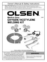
PIN - 0558010829
LEVER - 0558010838
OXY. VALVE - 0558010896
CUT VALVE
ASSEMBLY
08M05
NUT - 998580
F. G. VALVE - 0558010895
OXY. VALVE - 0558010896
R. H. CONNECTOR
0558010834
L. H. CONNECTOR
0558010835
Fig. 1 - Replacement Parts - Welding Torch and Cutting Attachment Assemblies
NUT - 802 (CA-4200)
NUT - 33A56 (CA-1500)

14
MAINTENANCE INSTRUCTIONS
For all repairs other than those covered below, send the ap-
paratus to your welding equipment distributor or to ESAB
Remanufacturing Center, 411 S. Ebenezer Road, Florence, SC
29501. Improperly repaired apparatus is hazardous.
Torch Handle and Cutting Attachment Throttle Valves -
Leakage around throttle valve can almost always be corrected
by tightening the packing nut slightly. If necessary, replace the
complete throttle valve assembly as directed below. If a valve will
not shut o completely loosen the packing nut and unscrew the
throttle valve assembly from the body. Wipe the stainless steel
ball seat on the valve stem, and the seating surface in the body,
with a clean cloth. Then reinstall the valve, retighten the packing
nut, and operate the valve several times, closing it with maximum
force. If this does not end the leakage, install a new throttle valve
assembly. When you do so, tighten the packing nut
Cutting Valve — If leakage is detected around the cutting valve,
or if the valve does not shut o completely when cutting oxygen
valve lever is released, unscrew the lock screw (see illustration
on pg. 8) with a spanner wrench. When the thread is fully dis-
engaged, lift out the valve assembly. Then tilt the attachment
and let the valve spring drop out in you hand.
Now pull the lock screw o the valve stem and remove seat and
retainer from the stem. Examine the stem carefully. If either the
seating surface or the cylindrical section that runs in the valve
screw is marred, replace the stem with a new part. Always replace
the seat with a new part. Replace the small 'O'-ring and replace
it if it is not in excellent condition. Place new seat on stem, slide
on the retainer, and insert stem in lock screw (be sure the lock
screw has both 'O'-rings in position). Finally, slide valve spring
into body, insert valve assembly, and tighten lock screw.
Cutting Attachment Mixer — To remove the mixer for cleaning
or replacement, back o locknut (56K07) until it reaches the
end of the threads on the adaptor (19K07). Continue turning
it, with a wrench, to unscrew the adaptor from the attachment
body. Then remove the mixer by grasping the end of the mixer
carefully with a pair of pliers and pull it out. Clean mixer center
orice with a No. 55 cleaning drill and the cross-drillings with a
No. 66 drill, or soak the mixer overnight in a solution of OXWELD
Nozzle Cleaning Compound (P/N 761F00), rinse, and blow dry
with clean air.
Inspect all 'O'rings and replace them if they are not in good
condition. Reassemble in reverse order, and tighten locknut
against body securely.
Welding Heads and Cutting Nozzles — Welding heads and cut-
ting nozzle orices should be cleaned by hand using OXWELD
tip cleaners, whenever a ame distortion is noted. Maintaining
clean orices is highly recommended for reducing any incidence
of ashbacks. If you do not have tip cleaners, twist drills of the
correct sizes (see Tables) may be used. Insert the drill carefully,
and push it back and forth. DO NOT TWIST THE DRILL.
If a welding tip requires replacement, secure the front end of
the mixer throat in a vise and unscrew the tip. Before installing
a new tip, be sure it matches the mixer throat in size (both parts
are size-stamped). Always tighten the new tip as much as you
can without bending it.
SECTION 3 MAINTENANCE
To clean a welding head mixer, unscrew it from the mixer
throat, soak it overnight in a solution of OXWELD Nozzle
Cleaning Compound, rinse with clear water, dry with a jet of
air.
Check the condition of ‘O’-rings on the welding heads periodi-
cally. If they appear to be in poor condition, or are so worn
that the head can be inserted in the handle without notice-
able resistance, replace them.

17
SOPLETE PARA SOLDAR WH-4200 con
ACCESORIOS DE CORTE CA-4200
Instructivo (ES)

26
Tabla 8-1567 Series - Uso general de Gas Combustible Boquillas de corte de dos piezas (High Precaliente)
Tabla 8A - 1564 Series One-Piece boquillas de corte FG-2 y la MAPP Gases Combustibles
Sleeve (External)
Nozzle Part No. Steel Gas Pressure, Gas Consumption, Cleaning
tfgispssenkcihT2-GF2-GFsaG .taNlanretnIelzzoN
3
/hr Drill Size
Size Part No. Propane mapp mapp in. mm. Oxygen Fuel Gas Oxygen FG-2 Nat. Gas Cutting
1567 Series (High Preheat)
1/8" 639614 1/8 3 20 - 40 5 - 10 20 - 25 79
1/4" 639615 1/4 6 45 - 65 5 - 10 20 - 25 69
1/2" 639616 639322 998277 998557 1/2 13 40 3 - 5 65 - 85 5 - 10 20 - 25 65
3/4" 639617 3/4 19 70 - 90 5 - 10 20 - 25 61
1" 639618 1 25 95 - 115 5 - 10 25 - 30 54
2" 639619 2 50 175 - 200 8 - 15 30 - 35 51
3" 639620 3 75 235 - 260 8 - 15 35 - 40 47
4" 998734 14Z39 114Z08 998561 4 100 300 - 335 10 - 15 35 - 40 46
8" 998735 6 150 40 450 - 480 10 - 15 40 - 45 39
14Z77 639755 998558 8 200 55 - 60 5 - 10 560 - 590
Use where high preheat intensity is desired.
Consumption of MAPP or propane is approximately the same as FG-2.
Use soft-bristled brush (750F99) to clean preheat slots of internal nozzles.
Heavy-duty sleeve (14Z96) available for use in place of 14Z77 sleeve.
Utilice un cepillo suave (750F99) para limpiar las ranuras del precalentador de las boquillas internas.
Propano
Gas Nat.
Consumo de gas pies
3/
hr. Gas combustible
Tamaño del
limpiador
Corte
Presión, psig
Gas combustible
Tamaño
de bo-
quilla
N/P
boquilla
(interna)
N/P camisa (externa)
Espesor del
acero
Oxígeno
FG-2 FG-2
mapp
mapp
pulg. mm
FG-2
Oxígeno
FG-2
Gas Nat.
Utilice donde se desea una alta intensidad de precalentamiento
El consumo de MAPP o propano de gas es aproximadamente la misma que FG-2.
Manga de trabajo pesado (14Z96) disponibles para su uso en el lugar o (14Z77) manga.
SECCIÓN 2 OPERACIÓN
Espesor
del metal
pulgadas
Tama-
ño
de la
punta
pulga-
das
Número
de pieza
Presión del gas
velo-
cidad de
corte
Consumo de Gas
Promedio
de Ancho
de ranura
oxígeno de
corte
psig
Precaliente el
oxígeno
psig
propileno
psig
ipm
El oxígeno
total
cfh
propileno
cfh
pulgadas
39
Cutting Tips
1564 Series Propylene Tips
Hand or Machine Cutting Tips
Metal Thickness Tip Size
Part
Number
Number
Preheat
Holes
Cleaning
Preheat
Drill Size Cutting
in. mm in. in.
1/8-1/2 10-19 1/2 638983 8 67 60
3/4-1
1
/
2
19-50 1
1
/
2
638984 8 64 53
2-4 50-100 4 638985 8 62 46
4-8 100-200 8 638986 8 59 39
8-12 200-300 12 638987 8 56 31
Operating Data
Metal
Thickness
Tip
Size
Part
Number
Gas Pressure
Cutting
Speed
Gas Consumption
Average
Kerf WidthCutting Oxygen Preheat Oxygen Propylene Total Oxygen Propylene
in. in. psig psig psig ipm cfh cfh in.
1/4 1/2 638983 20-25 20-50 3-5 18-24 55-60 3-4 .050
1/2 1/2 638983 30-35 20-50 3-5 14-22 70-80 4-5 .065
3/4 1
1
/
2
638984 30-35 20-50 3-5 12-20 135-155 7-8 .080
1 1
1
/
2
638984 35-40 20-50 3-5 11-17 150-155 7-8 .090
1
1
/
2
1
1
/
2
638984 40-45 20-50 3-5 10-15 160-210 8-9 .095
2 4 638985 25-30 20-50 3-5 9-13 215-245 8-10 .100
3 4 638985 30-35 25-55 3-5 8-10 235-290 8-10 .105
4 4 638985 35-40 25-55 3-5 6-9 270-320 10-11 .115
5 8 638986 25-35 25-55 5-10 5-7 325-410 10-11 .125
6 8 638986 35-45 25-55 5-10 4-6 410-480 11-13 .170
8 8 638986 55-65 30-60 5-10 3.5-4.5 580-670 15-17 .187
10 12 638987 40-50 30-60 10-15 2.5-3.5 680-805 20-23 .210
12 12 638987 55-65 30-60 10-15 2-3 845-975 22-28 .240
1500 Group Tips
One-piece alternate fuels
■ General purpose. Medium preheat
sufficient for cutting dirty plate
and for beveling
SINCE 1904
MADE IN THE USA
- Given pressures are torch inlet pressures, not what to set regulator at; hose length, diameter, ash arrestor use, and many other factors
affect pressure. Use test gauge adaptors on page 33 to check pressure at back of torch.
- When using tips larger than 6 in., ESAB recommends using straight (hand) cutting torches, not combination torches.

27
SECCIÓN 2 OPERACIÓN
CLAVIJA - 0558010829
PALANCA - 0558010838
VÁLVULA OXIGENO - 0558010896
VÁLVULA CORTAR
ASAMBLEA
08M05
TUERCA - 998580
VÁLVULA GAS COMBUSTIBLE - 0558010895
VÁLVULA OXIGENO - 0558010896
CONECTOR
LA MANO
DERECHA
0558010834
CONECTOR IZQUIERDA
0558010835
TUERCA - 802 (CA-4200)
TUERCA - 33A56 (CA-1500)

38
Tableau 8-1567 Series - General Purpose Fuel Gas deux pièces Buses de coupe (Haute Préchauer)
Tableau 8A - 1564 Series One-Piece buses de coupe FG-2 et MAPP gaz combustibles
Sleeve (External)
Nozzle Part No. Steel Gas Pressure, Gas Consumption, Cleaning
tfgispssenkcihT2-GF2-GFsaG .taNlanretnIelzzoN
3
/hr Drill Size
Size Part No. Propane mapp mapp in. mm. Oxygen Fuel Gas Oxygen FG-2 Nat. Gas Cutting
1567 Series (High Preheat)
1/8" 639614 1/8 3 20 - 40 5 - 10 20 - 25 79
1/4" 639615 1/4 6 45 - 65 5 - 10 20 - 25 69
1/2" 639616 639322 998277 998557 1/2 13 40 3 - 5 65 - 85 5 - 10 20 - 25 65
3/4" 639617 3/4 19 70 - 90 5 - 10 20 - 25 61
1" 639618 1 25 95 - 115 5 - 10 25 - 30 54
2" 639619 2 50 175 - 200 8 - 15 30 - 35 51
3" 639620 3 75 235 - 260 8 - 15 35 - 40 47
4" 998734 14Z39 114Z08 998561 4 100 300 - 335 10 - 15 35 - 40 46
8" 998735 6 150 40 450 - 480 10 - 15 40 - 45 39
14Z77 639755 998558 8 200 55 - 60 5 - 10 560 - 590
Use where high preheat intensity is desired.
Consumption of MAPP or propane is approximately the same as FG-2.
Use soft-bristled brush (750F99) to clean preheat slots of internal nozzles.
Heavy-duty sleeve (14Z96) available for use in place of 14Z77 sleeve.
Utilisez une brosse douce (750F99) pour nettoyer les fentes de buses interne préchauage.
propane
gaz naturel
Consommation en pi
3
/h
Gaz de chaue
Calibre
d’alésoir
nettoyage
Pression en psig
Gaz de chaue
Taille de
la buse
N / P
Boquilla
(interne)
N / P Manchon (externe)
Épaisseur de
l'acier
Oxygène
FG-2 FG-2
mapp
mapp
inch mm
FG-2
Oxygène
FG-2
gaz naturel
Utiliser où l'intensité de préchauage élevée est souhaitée.
La consommation de gaz MAPP ou le propane est à peu près le même que FG-2.
Manga lourd (14Z96) disponibles pour une utilisation sur site ou (14Z77) manga.
SECTION 2 EXPLOITATION
Metal
Thickness
in.
Tip
Size
in.
Part
Number
Gas Pressure
Cutting
Speed
Gas Consumption
Average
Kerf Width
Cutting Oxygen
psig
Preheat Oxygen
psig
Propylene
psig
ipm
Total Oxygen
cfh
Propylene
cfh
in.
39
Cutting Tips
1564 Series Propylene Tips
Hand or Machine Cutting Tips
Metal Thickness Tip Size
Part
Number
Number
Preheat
Holes
Cleaning
Preheat
Drill Size Cutting
in. mm in. in.
1/8-1/2 10-19 1/2 638983 8 67 60
3/4-1
1
/
2
19-50 1
1
/
2
638984 8 64 53
2-4 50-100 4 638985 8 62 46
4-8 100-200 8 638986 8 59 39
8-12 200-300 12 638987 8 56 31
Operating Data
Metal
Thickness
Tip
Size
Part
Number
Gas Pressure
Cutting
Speed
Gas Consumption
Average
Kerf WidthCutting Oxygen Preheat Oxygen Propylene Total Oxygen Propylene
in. in. psig psig psig ipm cfh cfh in.
1/4 1/2 638983 20-25 20-50 3-5 18-24 55-60 3-4 .050
1/2 1/2 638983 30-35 20-50 3-5 14-22 70-80 4-5 .065
3/4 1
1
/
2
638984 30-35 20-50 3-5 12-20 135-155 7-8 .080
1 1
1
/
2
638984 35-40 20-50 3-5 11-17 150-155 7-8 .090
1
1
/
2
1
1
/
2
638984 40-45 20-50 3-5 10-15 160-210 8-9 .095
2 4 638985 25-30 20-50 3-5 9-13 215-245 8-10 .100
3 4 638985 30-35 25-55 3-5 8-10 235-290 8-10 .105
4 4 638985 35-40 25-55 3-5 6-9 270-320 10-11 .115
5 8 638986 25-35 25-55 5-10 5-7 325-410 10-11 .125
6 8 638986 35-45 25-55 5-10 4-6 410-480 11-13 .170
8 8 638986 55-65 30-60 5-10 3.5-4.5 580-670 15-17 .187
10 12 638987 40-50 30-60 10-15 2.5-3.5 680-805 20-23 .210
12 12 638987 55-65 30-60 10-15 2-3 845-975 22-28 .240
1500 Group Tips
One-piece alternate fuels
■ General purpose. Medium preheat
sufficient for cutting dirty plate
and for beveling
SINCE 1904
MADE IN THE USA
- Given pressures are torch inlet pressures, not what to set regulator at; hose length, diameter, ash arrestor use, and many other factors
affect pressure. Use test gauge adaptors on page 33 to check pressure at back of torch.
- When using tips larger than 6 in., ESAB recommends using straight (hand) cutting torches, not combination torches.

ESAB AB
SE--695 81 LAXÅ
SWEDEN
Phone +46 584 81 000
www.esab.com
041227
ES AB subsidiaries and representative offices
Europe
AUSTRIA
ESAB Ges.m.b.H
Vienna--Liesing
Tel: +43 1 888 25 11
Fax: +43 1 888 25 11 85
BELGIUM
S.A. ESAB N.V.
Brussels
Tel: +32 2 745 11 00
Fax: +32 2 745 11 28
THE C ZECH REPUBLIC
ESAB VAMBERK s.r.o.
Prague
Tel: +420 2 819 40 885
Fax: +420 2 819 40 120
DENMARK
Aktieselskabet ESAB
Copenhagen--Valby
Tel: +45 36 30 01 11
Fax: +45 36 30 40 03
FINLAND
ESAB Oy
Helsinki
Tel: +358 9 547 761
Fax: +358 9 547 77 71
FRANCE
ESAB France S.A.
Cergy Pontoise
Tel: +33 1 30 75 55 00
Fax: +33 1 30 75 55 24
GERMANY
ESAB GmbH
Solingen
Tel: +49 212 298 0
Fax: +49 212 298 218
GREAT BRITAIN
ESAB Group (UK) Ltd
Waltham Cross
Tel: +44 1992 76 85 15
Fax: +44 1992 71 58 03
ESAB Automation Ltd
Andover
Tel: +44 1264 33 22 33
Fax: +44 1264 33 20 74
HUNGARY
ESAB Kft
Budapest
Tel: +36 1 20 44 182
Fax: +36 1 20 44 186
ITALY
ESAB Saldatura S.p.A.
Mesero (Mi)
Tel: +39 02 97 96 81
Fax: +39 02 97 28 91 81
THE N ETHERLANDS
ESAB Nederland B.V.
Utrecht
Tel: +31 30 2485 377
Fax: +31 30 2485 260
NORWAY
AS ESAB
Larvik
Tel: +47 33 12 10 00
Fax: +47 33 11 52 03
POLAND
ESAB Sp.zo.o.
Katowice
Tel: +48 32 351 11 00
Fax: +48 32 351 11 20
PORTUGAL
ESAB Lda
Lisbon
Tel: +351 8 310 960
Fax: +351 1 859 1277
SLOVAKIA
ESAB Slovakia s. r.o.
Bratislava
Tel: +421 7 44 88 24 26
Fax: +421 7 44 88 87 41
SPAIN
ESAB Ibérica S.A.
Alcalá de Henares (MADRID)
Tel: +34 91 878 3600
Fax: +34 91 802 3461
SWEDEN
ESAB Sverige AB
Gothenburg
Tel: +46 31 50 95 00
Fax: +46 31 50 92 22
ESAB International AB
Gothenburg
Tel: +46 31 50 90 00
Fax: +46 31 50 93 60
SWITZERLAND
ESAB AG
Dietikon
Tel: +41 1 741 25 25
Fax: +41 1 740 30 55
North and South Ameri ca
ARGENTINA
CONARCO
Buenos Aires
Tel: +54 11 4 753 4039
Fax: +54 11 4 753 6313
BRAZIL
ESAB S.A.
Contagem--MG
Tel: +55 31 2191 4333
Fax: +55 31 2191 4440
CANADA
ESAB Group Canada Inc.
Missisauga, Ontario
Tel: +1 905 670 02 20
Fax: +1 905 670 48 79
MEXI CO
ESAB Mexico S.A.
Monterrey
Tel: +52 8 350 5959
Fax: +52 8 350 7554
USA
ESAB Welding & Cutting Products
Florence, SC
Tel: +1 843 669 44 11
Fax: +1 843 664 57 48
Asia/Pacific
CHINA
Shanghai ESAB A/ P
Shanghai
Tel: +86 21 5308 9922
Fax: +86 21 6566 6622
INDIA
ESAB India Ltd
Calcutta
Tel: +91 33 478 45 17
Fax: +91 33 468 18 80
INDONESIA
P.T. ESABindo Pratama
Jakarta
Tel: +62 21 460 0188
Fax: +62 21 461 2929
JAPAN
ESAB Japan
Tokyo
Tel: +81 3 5296 7371
Fax: +81 3 5296 8080
MALAYSIA
ESAB (Malaysia) Snd Bhd
Shah Alam Selangor
Tel: +60 3 5511 3615
Fax: +60 3 5512 3552
SINGAPORE
ESAB Asia/Pacific Pte Ltd
Singapore
Tel: +65 6861 43 22
Fax: +65 6861 31 95
SOUTH KOREA
ESAB SeAH Corporation
Kyungnam
Tel: +82 55 269 8170
Fax: +82 55 289 8864
UNITED ARAB EMI R ATES
ESAB Middle East FZE
Dubai
Tel: +971 4 887 21 11
Fax: +971 4 887 22 63
Repr esentative offices
BULGARI A
ESAB Representative Office
Sofia
Tel/Fax: +359 2 974 42 88
EGYPT
ESAB Egypt
Dokki--Cairo
Tel: +20 2 390 96 69
Fax: +20 2 393 32 13
ROMANIA
ESAB Representative Office
Bucharest
Tel/Fax: +40 1 322 36 74
RUSSIA--CIS
ESAB Representative Office
Moscow
Tel: +7 095 937 98 20
Fax: +7 095 937 95 80
ESAB Representative Office
St Petersburg
Tel: +7 812 325 43 62
Fax: +7 812 325 66 85
Distributors
For addresses and phone
numbers to our distributors in
other countries, please visit our
home page
www.esab.com
/