Page is loading ...

F-12-310-K
January, 2001
INSTRUCTIONS for
C-32
CUTTING TORCH
Be sure this information reaches the operator.
You can get extra copies through your supplier.
Cutting Range using acetylene ............................ 1/8" - 12" (3 - 300 mm)
Cutting Range using other fuel gases .................. 1/8" - 3" (3 - 76 mm)
Cutting Nozzles ...................................................................... 1500 series
Torch-Hose Connections ........................ Oxy. CGA-022 (9/16" 18)
................................................................ F. G. CGA-023 (9/16" LH)
Torch Overall Length ....................................................... 21-in. (532 mm)
Weight ......................................................................... 3-1/2 lbs. (1.6 kg)
Cutting range can be extended to 12" by installing optional Medium-Pressure Fuel Gas (MPFG)
Mixer Assembly, P/N 01Y67, in place of factory installed P/N 01Y33 Acetylene Mixer Assembly.
Other fuel gases include natural gas, propane, FG-2, etc.
ADJUSTING GAS PRESSURES
Fuel Gas: Open the fuel gas valve about one turn. Turn
in the pressure-adjusting screw on the fuel gas regula-
tor until its delivery-pressure gauge registers the desired
pressure (see cutting chart on page 4). Then immedi-
ately close the fuel gas valve.
Oxygen: Open the cutting oxygen valve by depressing
its valve lever fully. Turn in the pressure-adjusting screws
on the oxygen regulator until its delivery-pressure gauge
registers the desired pressure (see cutting chart on page
4). Then release the cutting oxygen lever.
NOTE: When gaugeless regulators are used, do not
open torch valves. Merely turn in the pressure-
adjusting screws to the desired pressures as
indicated on the scales of regulator caps.
TESTING FOR LEAKS
Every cutting outfit should be thoroughly tested for leaks
after it is first hooked up, and at regular intervals there-
after. After all connections have been made, make sure
all valves on the torch handle are closed. Then turn in
OPERATING INSTRUCTIONS
CONNECTING
1. Attach regulators to the oxygen and fuel gas cylin-
ders. Follow all instructions supplied with the regu-
lators.
2. Attach oxygen and fuel gas hoses to the regulators
and to the torch, after making sure all metal seating
surfaces are clean. Tighten all connection nuts with
a wrench.
3. Attach nozzle to torch head, and tighten connection
nut with a wrench.
4. Check the valve packing nuts for tightness.
Flashbacks can cause serious burns.
Be sure gas flow is sufficient for head or nozzle size.
Adjust regulators for proper psig pressures.
Adjust throttle valves properly.
Keep torch in good repair.
DO NOT throttle back gases to use large head or nozzle
on thin material.
These INSTRUCTIONS are for experienced operators. If you are not fully familiar with the principles of operation and safe
practices for oxy-fuel gas equipment, we urge you to read our booklet Precautions and Safe Practices for Gas Welding,
Cutting and Heating, Form 2035. The same information appears in the Oxy-Acetylene Handbook which may be purchased
from any ESAB distributor. Do NOT permit untrained persons to install, operate, or maintain this equipment. Do NOT attempt
to install or operate this equipment until you have read and fully understand these instructions. If you do not fully understand
these instructions, contact your supplier for further information.
The cutting torch covered by these instructions is listed by Underwriters Laboratories only when using parts manufactured by
ESAB Welding & Cutting Products to the specifications on file with Underwriters Laboratories, Inc., and when they are used
in the gas service for which they are designed and listed. The use of other parts that cause damage for failure to the equipment
will void the manufacturers warranty.
!
CAUTION
®

2
These Safety Precautions are for your protection. They sum-
marize precautionary information from the references listed
in Additional Safety Information section. Before performing any
installation or operating procedures, be sure to read and fol-
low the safety precautions listed below as well as all other
manuals, material safety data sheets, labels, etc. Failure to ob-
serve Safety Precautions can result in injury or death.
PROTECT YOURSELF AND OTHERS - Some
welding, cutting and gouging processes are
noisy and require ear protection. Hot metal can
cause skin burns and heat rays may injure
eyes. Training in the proper use of the pro-
cesses and equipment is essential to prevent
accidents. Also:
1. Always wear safety glasses with side shields in any work area,
even if welding helmets, face shields, or goggles are also re-
quired.
2. Wear flameproof gauntlet type gloves, heavy long-sleeve shirt,
cuffless trousers, high-topped shoes, and a welding helmet or
cap for hair protection, to protect against hot sparks and hot
metal. A flameproof apron may also be desirable as protection
against radiated heat and sparks.
3. Hot sparks or metal can lodge in rolled up sleeves, trousers
cuffs, or pockets. Sleeves and collars should be kept buttoned,
and open pockets eliminated from the front of clothing.
4. Protect other personnel from hot sparks with a suitable non-
flammable partition or curtains.
5. Use goggles over safety glasses when chipping slag or grind-
ing. Chipped slag may be hot and can travel considerable dis-
tances. Bystanders should also wear goggles over safety
glasses.
FIRES AND EXPLOSIONS - Heat from a flame
can act as an ignition source. Hot slag or sparks
can also cause fires or explosions. Therefore:
1. Remove all combustible materials well away from the work
area or completely cover the materials with a protective non-
flammable covering. Combustible materials include wood,
cloth, sawdust, liquid and gas fuels, solvents, paints and coat-
ings, paper, etc.
2. Hot sparks or hot metal can fall through cracks or crevices in
floors or wall openings and cause a hidden smoldering fire on
the floor below. Make certain that such openings are protected
from hot sparks and metal.
3. Do not weld, cut, or perform any other hot work on materials,
containers, or piping until it has been completely cleaned so
that no substances on the material can produce flammable or
toxic vapors. Do not do hot work on closed containers. They
may explode.
4. Have fire extinguishing equipment handy for instant use, such
as a garden hose, a pail of water or sand, or portable fire
extinguisher. Be sure you are trained in its use.
5. After completing operations, inspect the work area to be sure
that there are no hot sparks or hot metal which could cause a
later fire. Use fire watchers when necessary.
6. For additional information, refer to NFPA Standard 51B, Fire
Prevention in Use of Cutting and Welding Processes, which
is available from the National Fire Protection Association,
Batterymarch Park, Quincy, MA 02269.
FUMES AND GASES - Fumes and gases, par-
ticularly in confined spaces, can cause dis-
comfort or injury. Do not breathe fumes or
gases from welding or cutting, Therefore:
1. Always provide adequate ventilation in the work area by natu-
ral or mechanical ventilation means. Do not weld, cut, or gouge
on materials such as galvanized steel, stainless steel, copper,
zinc, lead, beryllium, or cadmium unless positive mechanical
ventilation is provided. Do not breathe fumes and gases from
these materials.
2. If you develop momentary eye, nose, or throat irritation while
operating, this is an indication that ventilation is not adequate.
Stop work at once and take necessary steps to improve venti-
lation in the work area. Do not continue to operate if physical
discomfort persists.
3. Refer to ANSI/ASC Standard Z49.1 listed below for specific
ventilation recommendations.
EQUIPMENT MAINTENANCE - Faulty or improperly
maintained equipment, such as torches, hoses and
regulators, can result in poor work, but even more
important, it can cause injury or death through fires.
Therefore:
1. Always have qualified personnel perform the installation,
troubleshooting, and maintenance work. Do not operate or
repair any equipment unless you are qualified to do so.
2. Keep all oxy-fuel equipment free of grease or oil. Grease, oil,
and other similar combustible materials, when ignited, can burn
violently in the presence of oxygen.
3. Do not abuse any equipment or accessories. Keep equipment
away from heat and wet conditions, oil or grease, corrosive
atmospheres and inclement weather.
4. Keep all safety devices in position and in good repair.
5. Use equipment for its intended purpose. Do not modify it in
any manner.
GAS CYLINDER HANDLING - Gas cylinders, if
mishandled, can rupture or explode violently.
Sudden rupture of a cylinder, valve or relief de-
vice can injure or kill you. Therefore:
1. Use the proper gas for the process and use the proper pres-
sure reducing regulator designed to operate from the com-
pressed gas cylinder. Do not use adaptors to mount the regu-
lator on the cylinder. Maintain hoses and fittings in good con-
dition. Follow manufacturers operating instructions for mount-
ing the regulator to the gas cylinder.
2. Always secure cylinders in an upright position by chain or strap
to suitable hand trucks, benches, walls, post, or racks. Never
secure cylinders to work tables or fixtures where they may
become part of an electrical circuit.
3. When not in use, keep cylinder valves closed. Have the valve
protection cap in place on top of the cylinder if no regulators is
installed. Secure and move cylinders by using suitable hand
trucks. Avoid rough handling of cylinders.
4. Locate cylinders away from heat, sparks, or flame of a weld-
ing, cutting, or gouging operation. Never strike an arc on a
cylinder.
5. For additional information, refer to CGA Standard P-1, Pre-
cautions for Safe Handling of Compressed Gases in Cylin-
ders:, which is available from the Compressed Gas Associa-
tion, 1235 Jefferson Davis Highway, Arlington, VA 22202.
ADDITIONAL SAFETY INFORMATION - For more in-
formation on safe practices for oxy-fuel welding and
cutting equipment, ask your distributor for a copy of
Precautions and Safe Practices for Gas Welding, Cut-
ting, and Heating, Form 2035. Gas apparatus safety
guidelines are also available on video cassettes from
your distributor.
The following publications, which are available from the American
Welding Society, 550 N.W. LeJuene Road, Miami, FL 33126, are
recommended to you:
1. ANSI/AWS Z49.1 - Safety in Welding and Cutting.
2. AWS F4.1 - Recommended Safe Practices for the Prepara-
tion for Welding and Cutting of Containers and Piping That
Have Held Hazardous Substances/
3. AWS SP - Safe Practices - Reprint, Welding Handbook.
Used to call attention to immediate hazards
which, if not avoided, will result in immediate,
serious personal injury or loss of life.
Used to call attention to potential hazards
which could result in personal injury or loss of
life.
Used to call attention to hazards which could
result in minor personal injury.
This symbol appearing in this manual means
Attention! Be Alert! Your safety is involved.
SP-GA 7/97
SAFETY PRECAUTIONS

3
the regulator pressure-adjusting screws until the oxy-
gen delivery-gauge registers 60 psi and the fuel gas
delivery-pressure gauge register 10 psi. Using Leak Test
Solution that is suitable for oxygen service, such as P/N
998771 (8 oz. container), check for leaks at the cylinder
valves, the cylinder-to-regulator connections, and regu-
lator-to-hose connections. If bubbling at any point indi-
cates leakage, tighten the connection. If this does not
stop the leakage, close the appropriate cylinder valve,
open the corresponding torch valve to remove all pres-
sure from the line, and finally release the regulator pres-
sure-adjusting screw by turning it counterclockwise. Then
break the leaky connection, wipe metal seating surfaces
with a clean cloth, and examine then for nicks and
scratches. Remake the connection(s) and retest. Do not
try to light the torch until you are satisfied that all con-
nections are gas-tight.
After lighting the torch and adjusting the flames, use leak
test solution to check for leakage at all torch valves and
at the nozzle nut.
LIGHTING AND FLAME ADJUSTMENT
1. Open the preheat oxygen valve on the torch about
1/8 turn.
2. Open the fuel gas valve on the torch about 1/8 turn
and light the gas at the nozzle with a friction lighter.
DO NOT USE A MATCH. Use of a match can seri-
ously burn your hand.
3. If using acetylene, open fuel gas valve until preheat
flames leave the end of the nozzle and then close
just enough to return the flames to the nozzle. De-
press lever to open cutting oxygen valve and then
readjust preheat flames to neutral by opening pre-
heat oxygen valve gradually.
If using FG-2 or other fuel gases but acetylene, open
fuel gas valve until flames just starts to leave the
end of the nozzle and then open the preheat oxy-
gen valve until the flames are at their shortest length.
Depress the cutting oxygen valve lever and then
readjust the preheat flames to the shortest length
by opening the preheat oxygen valve gradually.
The above procedure usually provides adequate pre-
heat for the nozzle in use. If desiring to change the
preheat flames, always hold the cutting oxygen valve
open while readjusting the preheat oxygen and fuel
gas valves.
SHUTTING OFF
Release the cutting oxygen valve lever. Then close the
fuel gas valve, and finally the preheat oxygen valve.
If operations are to be stopped for a half-hour or more,
all pressure should be released from the torch, hoses,
and regulators by doing the following:
1. Close each cylinder or station valve.
2. Open torch valves.
3. After relieving the gases, back out the pressure-ad-
justing screw of each regulator and close the torch
valves.
OPERATING PRECAUTIONS
Do not exceed 15 psig acetylene during operation.
Flow: There must be proper flow of gases for safe
operation and full performance. This requires the follow-
ing three conditions: (1) the regulators that determine
the inlet pressure to the hoses must be set to the correct
pressure: (2) the hoses and their connectors must have
adequate capacity for the job (hoses that are too long,
too small or have connectors with small passageways
can cause problems); and (3) the throttle valves on the
torch must be adjusted with the procedure shown in
these instructions.
Note: Items (1) and (2) can be checked by measuring
the gas pressures at the torch. Gauge adaptors
are available for this purpose.
Backfire: Improper operation of the torch may cause
the flames to go out with a loud pop. Such a backfire
may be caused by contact of nozzle with the work, by
spatter from the work, by the use of incorrect gas pres-
sures, or by leakage at the cutting nozzle seats due to
dirt or nicks on seats or to a loose nozzle nut.
Flashback: Under certain circumstances, the flame may
not pop out (backfire) but instead burn back inside the
torch with a shrill hissing or squeal. This is called a flash-
back. A flashback should never occur if (1) the equip-
ment is in good condition; (2) preheat ports on cutting
nozzles or welding tips are cleaned frequently; (3) oper-
ating pressures are correct; and (4) throttle valves are
adjusted properly. Should a flashback occur, IMMEDI-
ATELY shut off the torch. Allow it to cool off for at least a
minute. Then check your nozzle or tip, gas pressures,
readjust regulators if necessary, and relight the torch. If
flashback recurs, send the torch with nozzle in use when
flashback occurred to your distributor for repair.
ACCESSORIES
Special rosebud heating nozzles are available to replace
the cutting nozzle for multi-flame heating applications:
No. 55 O-A Heating Nozzle, P/N 20238 (for acetylene
use only.
No. 70 O-FG Heating Nozzle, P/N 20234 (for fuel gases
other than acetylene).

4
OPERATING DATA, CLEANING DATA, and PART NUMBERS
GENERAL NOTES:
1. Pressures given are measured at the torch; therefore, pressure drop through hose should be considered when setting
pressure at the regulator. Generally, 1/4-in. hoses up to 25-ft. long are adequate for cutting steel up to 4-in. thick. If longer
hoses are required and if cutting thicker steel, 3/8-in. hoses should be used.
2. The tables show average values based on typical conditions. The type and quality of steel, its surface condition, the purity
of oxygen, etc. will aways have a bearing on the end results.
Acetylene Cutting Nozzles
Nozzle Steel Gas Pressure, psig Gas Consumption, ft
3
/hr Cleaning
Thickness Drill Size
Size Part No. in. mm Oxygen Acetylene Oxygen Acetylene Preheat Cutting
1565 Series (Low Acetylene Consumption)
1/8" 639182 1/8 3 30 - 40 78
1/4" 639263 1/4 6 35 - 40 69
1/2" 639264 1/2 13 55 - 65 5 - 9 73 65
3/4" 639265 3/4 19 40 5 - 7 60 - 70 61
1" 639266 1 25 85 - 95 54
2" 639267 2 50 155 - 165 8 - 12 70 51
3" 639268 3 75 215 - 230 10 - 12 69 47
4" 639269 4 100 340 - 360 15 - 20 65 40
6" 998742 6 150 35 - 45 8 - 10 395 - 460 20 - 25 57 39
8 200 55 - 65 545 - 625 30 - 35
10" 998743 10 250 40 - 55 8 - 10 630 - 710 40 - 45 56 31
12 300 55 - 65 10 - 12 790 - 905 45 - 55
1502 Series (Medium Preheat)
1/4" 08Z67 1/4 6 20 - 25 5 - 7 35 - 45 6 - 8 69 68
1/2" 15Z17 1/2 13 30 - 35 65 - 75 8 - 10 66 60
1-1/2" 15Z18 3/4 19 39 - 35 5 - 7 120 - 135 14 - 16 65 53
1 25 35 - 40 130 - 140 14 - 16
4" 15Z19 2 50 25 - 30 6 - 8 185 - 210 16 - 20 60 46
3 75 30 - 40 205 - 255 16 - 20
4 100 35 - 45 235 - 285 19 - 22
8" 15Z20 6 150 35 - 45 6 - 10 395 - 460 20 - 25 57 39
8 200 55 - 65 545 - 625 30 - 35
12" 15Z21 10 250 45 - 55 8 - 10 630 - 710 40 - 45 56 31
12 300 55 - 65 10 - 12 790 - 905 45 - 55

5
MAINTENANCE INSTRUCTIONS
For all repairs other than those covered below, send
the apparatus to your ESAB distributor or ESAB Re-
manufacturing Center, 411 S. Ebenezer Road, Flo-
rence, SC 29501. Improperly repaired apparatus is
hazardous.
Preheat Valves: Leakage around either throttle valve
can usually be corrected by tightening the packing nut
slightly. If this does not stop the leakage, replace the
throttle valve assembly.
If either preheat valve fails to shut off completely, re-
move the valve assembly from the torch. With a clean
cloth, wipe the ball in the end of the stem. Then reinsert
valve assembly and tighten it several times with maxi-
mum force. If this does not eliminate leakage, try a new
valve assembly. If then the valve does not shut off com-
pletely, send the torch to a repair station for reseating of
the body.
After installing a new valve assembly, tighten the pack-
ing nut until the valve can be turned only with great diffi-
culty, and set the unit aside, for three or four hours at
least, to set the packing. Then back off the packing nut
until the valve turns readily.
Cutting Valve: If leakage develops around the cutting
valve stem or between the cutting valve guide and the
torch body, or if the cutting valve fails to shut off com-
pletely, proceed as follows:
1. Remove cutting valve lever. Drive out the fulcrum
roll pin with a 7/32-in. diam. rod.
2. Unscrew cutting valve guide and lift out entire valve
assembly; guide (with external and internal O-rings)
valve stem, spring, and O-ring retaining washer.
3. Pull stem out of guide. Replace it with new part un-
less the molded rubber seat appears to be in excel-
lent condition.
4. Remove the internal O-ring (85W10) from the guide.
Before installing new O-ring lubricate sparingly with
silicone lubricant (17672 - 1 oz. tube). Replace the
external O-ring (638797) if it shows distinct signs of
wear.
5. Reassemble by placing retaining washer and spring
in guide, then placing stem through spring and O-
ring in guide.
6. Screw valve assembly into body. Before reassem-
bling cutting lever, connect torch to oxygen source,
apply at least 60 psi pressure, and check for leak-
age through the valve, around the stem, and around
the guide.
7. Reassemble cutting lever to torch. Install roll pin with
slot facing the body.
Fuel Gas Two-Piece Cutting Nozzles
NOTE: Do NOT use with acetylene.
Sleeve External
Nozzle Part No. Steel Gas Pressure, Gas Consumption Cleaning
Nozzle (Internal) Nat. Gas FG-2 FG-2 Thickness psig ft
3
/hr Drill Size
Size Part No. Propane MAPP MAPPu in. m m Oxygen Fuel Gas Oxygen FG-2n Nat. Gas Cuttingl
1567 Series (High Preheat)
1/8" 639614 639322 998277 998557 1/8 3 40 3 - 4 20 - 40 5 - 10 20 - 25 79
1/4" 639615 1/4 6 3 - 4 45 - 65 5 - 10 20 - 20 69
1/2" 639616 1/2 13 3 - 4 65 - 85 5 - 10 20 - 25 65
3/4" 639617 3/4 19 3 - 4 70 - 90 5 - 10 20 - 25 61
1" 639618 1 25 4 - 5 95 - 115 5 - 10 25 - 30 54
2" 639619 2 50 4 - 5 175 - 200 8 - 15 30 - 35 51
3" 639620 3 75 6 - 7 235 - 260 8 - 15 35 - 40 47
4" 998734 14Z39 114Z08 998561 4 100 40 5 - 10 300 - 335 15 - 20 35 - 40 46
8" 998735 14Z77* 639755 998558 6 150 39 5 - 10 450 - 480 15 - 20 40 - 45 39
8 200 55 - 60 5 - 10 560 - 590 20 - 25 45 - 55
12" 998736 14Z69 998269 998559 10 250 50 - 60 10 - 15 840 - 900 25 - 30 55 - 65 31
12 300 60 - 70 10 - 15 900 - 970 25 - 30 55 - 65
1534 Series (Medium Preheat)
2 14Z66 14Z38 114Z07 998560 1/8 3 25 3 - 4 25 - 45 5 - 10 15 - 20 76
3 14Z50 1/4 6 30 45 - 65 68
4 14Z51 1/2 13 30 70 - 90 60
6 14Z52 14Z39 114Z08 998561 3/4 19 30 3 - 4 125 - 145 5 - 10 15 - 20 53
1 25 35 140 - 160
8 14Z53 14Z39 114Z08 998561 2 50 25 4 - 5 150 - 170 8 - 15 30 - 40 46
3 75 40 280 - 300
4 100 40 258 - 305
u Use where high preheat intensity is desired.
n Consumption of MAPP or propane is approximately the same as FG-2.
l Use soft-bristled brush (750F99) to clean preheat slots of internal nozzles.
* Heavy-duty sleeve (14Z96) available for use in place of 14Z77 sleeve.

6
Mixer. To remove the mixer for cleaning or replacement,
first unscrew the mixer chamber plug. Then let the two
springs drop out in your hand. Finally, dislodge the mixer
and its three washers (two brass, one neoprene) either
by rapping the torch, held vertically, against a block of
soft wood, or by turning a long 10-32 machine screw
into the thread in the end of the mixer and pulling it out.
When reassembling, place the three washers (one neo-
prene between two brass) on the extreme back end of
the mixer. (Be sure to use a new neoprene washer un-
less the old one appears to be in equal-to-new condi-
tion.) Slip mixer into torch, then insert large spring and
push it down hard to seat the forward brass washer
against shoulder in body. Then drop small spring inside
large spring, insert mixer plug, and tighten plug firmly.
Be sure the mixer chamber plug is fitted with an O-ring
in good condition (even in cases where the plug carried
no O-ring originally).
Cleaning Cutting Nozzles: Cutting nozzle orifices
should be cleaned by hand, using OXWELD tip clean-
ers, whenever a flame distortion is noticed. Maintaining
clean orifices is highly recommended for reducing any
incidence of flashbacks. If you do not have tip cleaners,
twist drills of the correct sizes (see table on pg. 4) may
be used. Insert the drill carefully, and push it back and
forth. DO NOT TWIST THE DRILL.
To clean preheat slots on fuel gas internal nozzles, re-
move the external sleeve and use a soft bristled brush
(750F99).
For longer life, nozzles should be cleaned periodically in
a solution of OXWELD Nozzle Cleaning Compound (P/
N 761F00) made up and used as directed on the jar in
which it is packed.
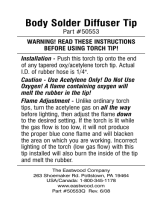
PARTS INFORMATION
All parts which can be replaced without breaking soldered or brazed joints are illustrated and listed below. When
ordering parts, please give both part number and description (including size where appropriate). Parts may be ordered
from your ESAB distributor or from ESAB Welding and Cutting Products, Customer Service Department, Florence,
SC.

7
28Z43
SPRING
3924
SPRING
77Z29
WASHER
77Z30
WASHER
77Z29
WASHER
C-32 Cutting Torch (75-deg. head - 21" long) ................................... P/N 01X23
C-32 Cutting Torch (90-deg. head - 21" long) ................................... P/N 01X26
01Y33 (ACET.)
MIXER ASSEMBLY
33A56
NUT
7/8-20
3/8-24
DRILL AT ASSEMBLY
#52 (.0635) DRILL
PIN
6262-0009
50Z37
LATCH
50Z38
THUMBPIECE
62321644
PIN
51Z31
INSERT
638981 LEVER ASSEMBLY
OPTIONAL MIXER ASSEMBLY: 01Y67
for Med. Pressure Fuel Gas (MPFG)
(Includes O-ring 86W04)
9/16-25
86W85
ORING
134Z55
PLUG
(2) 54A87 THROTTLE
VALVE ASSEM.
ORING - 638797
STEM - 638930
SPRING - 29Z37
WASHER - 638241
ORING - 85W10
GUIDE - 638240

F-12-310-K 1/2001 Printed in U.S.A.
IF YOU DO NOT KNOW WHOM TO CALL
Telephone: (800) ESAB-123/ Fax: (843) 664-4452/ Web:http://www.esab.com
Hours: 7:30 AM to 5:00 PM EST
A. CUSTOMER SERVICE QUESTIONS:
Order Entry Product Availability Pricing Delivery
Order Changes Saleable Goods Returns Shipping Information
Eastern Distribution Center
Telephone: (800)362-7080 / Fax: (800) 634-7548
Central Distribution Center
Telephone: (800)783-5360 / Fax: (800) 783-5362
Western Distribution Center
Telephone: (800) 235-4012/ Fax: (888) 586-4670
B. ENGINEERING SERVICE: Telephone: (843) 664-4416 / Fax : (800) 446-5693
Welding Equipment Troubleshooting Hours: 7:30 AM to 5:00 PM EST
Warranty Returns Authorized Repair Stations
C. TECHNICAL SERVICE: Telephone: (800) ESAB-123/ Fax: (843) 664-4452
Part Numbers Technical Applications Hours: 8:00 AM to 5:00 PM EST
Performance Features Technical Specifications Equipment Recommendations
D. LITERATURE REQUESTS: Telephone: (843) 664-5562 / Fax: (843) 664-5548
Hours: 7:30 AM to 4:00 PM EST
E. WELDING EQUIPMENT REPAIRS: Telephone: (843) 664-4487 / Fax: (843) 664-5557
Repair Estimates Repair Status Hours: 7:30 AM to 3:30 PM EST
F. WELDING EQUIPMENT TRAINING:
Telephone: (843)664-4428 / Fax: (843) 679-5864
Training School Information and Registrations Hours: 7:30 AM to 4:00 PM EST
G. WELDING PROCESS ASSISTANCE:
Telephone: (800) ESAB-123 / Fax: (843) 664-4454 Hours: 7:30 AM to 4:00 PM EST
H. TECHNICAL ASST. CONSUMABLES:
Telephone : (800) 933-7070 Hours: 7:30 AM to 5:00 PM EST
ESAB Welding & Cutting Products, Florence, SC Welding Equipment
COMMUNICATION GUIDE - CUSTOMER SERVICES
/