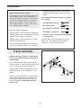
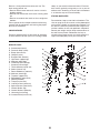
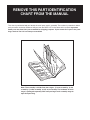
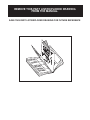
Weslo Gym 2500 is a multipurpose weight system that offers a full-body workout. Thanks to its design, it allows for weightlifting exercises customized to your needs and preferences, which can aid you in building muscle mass, and burning calories. It features High and Low Pulley Stations, the latter of which allows leg exercises while seated. Additionally, you will find a Press Arm, and Butterfly Arms for upper body workouts.
Weslo Gym 2500 is a multipurpose weight system that offers a full-body workout. Thanks to its design, it allows for weightlifting exercises customized to your needs and preferences, which can aid you in building muscle mass, and burning calories. It features High and Low Pulley Stations, the latter of which allows leg exercises while seated. Additionally, you will find a Press Arm, and Butterfly Arms for upper body workouts.


-
 1
1
-
 2
2
-
 3
3
-
 4
4
-
 5
5
-
 6
6
-
 7
7
-
 8
8
-
 9
9
-
 10
10
-
 11
11
-
 12
12
-
 13
13
-
 14
14
-
 15
15
-
 16
16
-
 17
17
-
 18
18
-
 19
19
-
 20
20
-
 21
21
-
 22
22
-
 23
23
-
 24
24
-
 25
25
-
 26
26
-
 27
27
-
 28
28
-
 29
29
-
 30
30
-
 31
31


Weslo Gym 2500 User manual
- Type
- User manual
- This manual is also suitable for
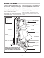
Weslo Gym 2500 is a multipurpose weight system that offers a full-body workout. Thanks to its design, it allows for weightlifting exercises customized to your needs and preferences, which can aid you in building muscle mass, and burning calories. It features High and Low Pulley Stations, the latter of which allows leg exercises while seated. Additionally, you will find a Press Arm, and Butterfly Arms for upper body workouts.
Ask a question and I''ll find the answer in the document
Finding information in a document is now easier with AI
Related papers
Other documents
-
Weider WESY1951 User manual
-
-
WeiderPro WEEVSY5923 User manual
-
-
-
-
-
-
-