
xx
MSO4000B and DPO4000B Series
Digital Phosphor Oscilloscopes
ZZZ
Service Manual
*P077051201*
077-0512-01


MSO4000B and DPO4000B Series
Digital Phosphor Oscilloscopes
ZZZ
Service Manual
xx
This document applies to firmware version 1.00 and above.
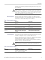
Warning
The servicing instructions are for use by qualified personnel
only. To avoid personal injury, do not perform any servicing
unless you are qualified to do so. Refer to all safety summaries
prior to performing service.
www.tektronix.com
077-0512-01

Copyright © Tektronix. All rights reserved. Licensed software products are owned by Tektronix or its subsidiaries
or suppliers, and are protected by national copyright laws and international treaty provisions.
Tektronix products are covered by U.S. and foreign patents, issued and pending. Information in this publication
supersedes that in all previously published material. Specifications and price change privileges reserved.
TEKTRONIX and TEK are registered trademarks of Tektronix, Inc.
Contacting Tektronix
Tektronix, Inc.
14150 SW Karl Braun Drive
P.O. Box 500
Beaverto
n, OR 97077
USA
For product information, sales, service, and technic al support:
In North America, call 1-800-833-9200.
Worldwide, visit www.tektronix.com to find contacts in your area.

Table of Contents
General Safety Summary ......................................................................................... iv
Preface ............................................................................................................. vii
Manual Conventions......................................................................................... vii
Where to Fin
d Operating Information............................................................................ 1
Theory of Operation................................................................................................ 3
Power Supply................................................................................................... 3
I/O Board ....................................................................................................... 3
Main Board and Analog Board............................................................................... 3
Front-Panel Board ............................................................................................. 4
Adjustm
ent Procedure.............................................................................................. 7
Required Equipment........................................................................................... 7
Before Adjustments............................................................................................ 8
Navigating During Adjustments ............................................................................. 8
Connecting the Equipment.................................................................................... 9
Factory Adjustment Procedure .............................................................................. 10
Sett
ing the Calibrator Output Signal........................................................................ 13
Maintenance........................................................................................................ 19
Preventing ESD ............................................................................................... 19
Inspection and Cleaning...................................................................................... 19
Module Removal.............................................................................................. 23
Troubleshooting............................................................................................... 25
Tr
oubleshooting Procedure .................................................................................. 25
Unpacking and Repacking Instructions .................................................................... 29
Replaceable Parts List............................................................................................. 31
Parts Ordering Information .................................................................................. 31
Using the Replaceable Parts List............................................................................ 32
MSO4000B and DPO4000B Series Digital Phosphor Oscilloscopes Service Manual i

Table of Contents
List of Figure
s
Figure 1: Four-channel model MSO4000B and DPO4000B series block diagram ......................... 5
Figure 2: Tw
o-channel model MSO4000B and DPO4000B series block diagram.......................... 6
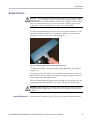
Figure 3: Removing tabs from the front protective cover..................................................... 23
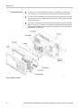
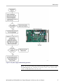
Figure 4: Module locator ......................................................................................... 24
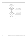
Figure 5: Primary troubleshooting procedure .................................................................. 26
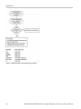
Figure 6: AC power supply troubleshooting procedure....................................................... 27
Figure 7: Module isolation troubleshooting procedure........................................................ 28
Figure 8:
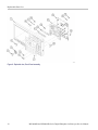
Exploded view, Front Panel assembly............................................................... 34
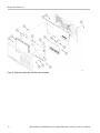
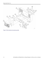
Figure 9: Display, Analog board, and Main board assembly ................................................ 36
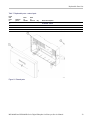
Figure 10: Rear chassis and connecting modules.............................................................. 38
Figure 11: External parts ......................................................................................... 39
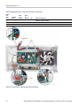
Figure 12: Rear chassis, showing cables and connectors ..................................................... 40
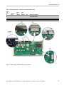
Figure 13: Main board, showing cable and connectors ....................................................... 41
ii MSO4000B and DPO4000B Series Digital Phosphor Oscilloscopes Service Manual

Table of Contents
List of Tables
Table 1: External inspection checklist........................................................................... 21
Table 2: Int
ernal inspection checklist ........................................................................... 21
Table 3: Parts list column descriptions.......................................................................... 32
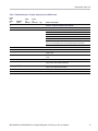
Table 4: Replaceable parts – Front Panel assembly ........................................................... 33
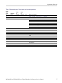
Table 5: Replaceable parts – Display, Analog board, and Main board ...................................... 35
Table 6: Replaceable parts – Rear chassis and connecting modules ........................................ 37
Table 7: Replaceable parts – external parts..................................................................... 39
Table 8: R
eplaceable parts – cable and connectors, rear chassis ............................................. 40
Table 9: Replaceable parts – cable and connectors, Main board ............................................. 41
MSO4000B and DPO4000B Series Digital Phosphor Oscilloscopes Service Manual iii

General Safety Summary
General Safet
ySummary
Review the fo
llowing safety precautions to avoid injury and prevent damage to
this product or any products connected to it.
To avoid potential hazards, use this product only as specified.
Only qualified personnel should perform service procedures.
To Avoid Fire or Personal
Injury
Use proper power cord. Use only the power cord specified for this product and
certified for the country of use.
Connect and disconnect properly. Do not connect or disconnect probes or test
leads while they are connected to a voltage source.
Connect and disconnect properly. De-energize the circuit under test before
connecting or disconnecting the current probe.
Ground the product. This product is grounded through the grounding conductor
of the power cord. To a void electric shock, the grounding conductor must be
connected to earth ground. Before making connections to the input or output
terminals of the product, ensure that the product is properly grounded.
Observe all terminal ratings. To avoid fire or shock hazard, observe all ratings
and markings on the product. Consult the product manual for further ratings
information before making connections to the product.
Connect the probe reference lead to earth ground only.
Do not apply a potential to any terminal, including the common terminal, that
exceeds the maximum rating of that termi
nal.
Power disconnect. The power cord disconnects the product from the power source.
Donotblockthepowercord;itmustremain accessible to the user at all times.
Do not operate without covers. Do not operate this product with covers or panels
removed.
Do not operate with suspected failures. If you suspect that there is damage to this
product, have it inspected by qualified service personnel.
Avoid exposed circuitry. Do not touch exposed connections and components when
power is present.
Do not operate in wet/damp conditions.
Do not operate in an explosive atmosphere.
Keep product surfaces clean and dry.
Provide proper ventilation. Refer to the manual’s installation instructions for
details on installing the product so it has proper ventilation.
iv MSO4000B and DPO4000B Series Digital Phosphor Oscilloscopes Service Manual

General Safety Summary
TermsinThisManual
These terms may
appear in this manual:
WARNING. Warning statements identify conditions or practices that could result
in injury or loss of life.
CAUTION. Caution statements identify conditions or practices that could result in
damage to this product or other property.
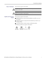
Symbols and Terms on the
Product
These terms may appear on the product:
DANGER in
dicates an injury hazard immediately accessible as you read
the m arking.
WARN IN G
indicates an injury hazard not immediately a ccessible as you
read the marking.
CAUTIO
N indicates a hazard to property including the product.
The following symbol(s) may appear on the product:
MSO4000B and DPO4000B Series Digital Phosphor Oscilloscopes Service Manual v

General Safety Summary
vi MSO4000B and DPO4000B Series Digital Phosphor Oscilloscopes Service Manual

Preface
This service manual provides information that you need to troubleshoot,
disassemble, and replace parts on the following Tektronix oscilloscopes:
Model Bandwidth Analog Channels
MSO4104B 1 GHz
4
MSO4104B-L 1 GHz
4
MSO4102B 1 GHz
2
MSO4102B-L 1 GHz
2
MSO4054B
500 MHz 4
MSO4034B
350 MHz 4
DPO4104B 1 GHz
4
DPO4104B-L 1 GHz
4
DPO4102B 1 GHz
2
DPO4102B-L 1 GHz
2
DPO4054B
500 MHz 4
DPO4034B
350 MHz 4
Manual Conventions
This manual uses certain conventions that you should become familiar with
before performing service.
Modules
Throughout this manual, any replaceable component, assembly, or part is referred
to by the term module.
Replaceable Parts
This manual refers to any field-replaceable assembly or mechanica l part
specifically by its name or generically as a replaceable part. In general, a
replaceable part is any circuit board or assembly, such as the hard disk drive, or a
mechanical part, such as the I/O port connectors, that is listed in the replaceable
parts list.
Safety
Symbols and terms related to safety appear in the General Safety Summary.
Information for service procedures appears in both the General Safety Summary
and the Service Safety Summary.
MSO4000B and DPO4000B Series Digital Phosphor Oscilloscopes Service Manual vii

Preface
viii MSO4000B and DPO4000B Series Digital Phosphor Oscilloscopes Service Manual

WheretoFindOperatingInformation
For information on installing and operating your DPO4000B or your MSO4000B
Series Digital Phosphor Oscilloscope, refer to the Tektronix MSO4000B Series
and DPO4000B
Series Digital Phosphor Oscilloscopes User Manual, which was
provided with your oscilloscope. This manual is also available, in 11 languages,
at www.tektronix.com/manuals.
MSO4000B and DPO4000B Series Digital Phosphor Oscilloscopes Service Manual 1

Where to Find Operating Information
2 MSO4000B and DPO4000B Series Digital Phosphor Oscilloscopes Service Manual

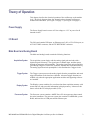
Theory of Operation
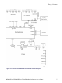
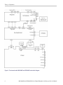
This chapter describes the electrical operation of the oscilloscope to the module
level. The block diagrams show four-channel and two-channel oscilloscope
module inter
connections. (See Figure 1 on page 5.) (See Figure 2 on page 6.)
Power Supply
The Power S
upply board converts AC line voltage to +12 V to power for all
internal circuits.
I/O Board
The I/O board contains USB ports, an Ethernet port (LAN), a VGA Video port, an
AUX OUT BNC connector, and an EXT REF IN BNC connector.
Main Board and Analog Board
The Main and Analog boards contain the following functions:
Acquisition System
The Ac
quisition system begins with the analog signal path and ends with a
digitized signal in memory. The signal enters a c hannel input, and then passes
through an attenuator and preamplifier. The analog signal from each preamplifier
goes through a digitizer, a time base controller, and then into acquisition memory.
The analog signal from each preamplifier is also distributed to a trigger c ircuit.
Trigger System
The Trigger system processes the analog signals from the preamplifiers and sends
trigger information to the time-base controller. Advanced trigger functions are
enabled only when the appropriate application modules and supporting software
are installed.
Di
splay System
The Display system combines live waveform data from acquisition memory with
menus and text, and stores this information in display memory. It then uses this
data to refresh the XGA display module (LCD).
Processor System
The Processor system contains a 460EX Power PC microprocessor that controls
the entire instrument. The process or system also contains FLASH ROM, system
RAM, and interfaces to USB ports and the Ethernet port.
MSO4000B and DPO4000B Series Digital Phosphor Oscilloscopes Service Manual 3

Theory of Operation
Power Converter
The Power Conve
rter receives +12 V power and +5 V standby power from the
main power s upply and generates voltages for the analog and digital c ircuitry on
the Main board. The front panel receives the +5 V standby power, and uses input
from the power switch to turn the oscilloscope on and off.
Front-Panel Board
The Front Panel board contains a microprocessor that reads the front-panel buttons
and controls, and then s ends this information to the processor system on the Main
board. The Front Panel board also generates the probe compensation output signal
and provid
es an interface to the application modules.
4 MSO4000B and DPO4000B Series Digital Phosphor Oscilloscopes Service Manual

Theory of Operation
Figure 1: Four-channel model MSO4000B and DPO4000B series block diagram
MSO4000B and DPO4000B Series Digital Phosphor Oscilloscopes Service Manual 5

Theory of Operation
Figure 2: Two-channel model MSO4000B and DPO4000B series block diagram
6 MSO4000B and DPO4000B Series Digital Phosphor Oscilloscopes Service Manual

Adjustment Procedure
This section contains the factory adjustment procedure for the DPO4000B Series
and the MSO4000B Series oscilloscopes. Only qualified personnel should
perform adjustment procedures.
Required Eq
uipment
The following equipment, or a suitable equivalent, is required to c omplete these
procedures.
The follow
ing table specifies the equipment that is required to adjust the
DPO4000B Series oscilloscopes.
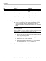
Description Minimum requirements Example
DC voltage source 20 mV to 100 V into 1 MΩ
6Vinto50Ω
±0.1% amplitude accuracy
Fluke 9500B Oscilloscope
Calibrator with 9530 active
heads
Time Mark Generator 1.6 ms (625 Hz), 0.5
p-p
symmetrical about 0 V into
50 Ω.
Fluke 9500B Oscilloscope
Calibrator with one 9530
head
Sine Generator Symmetrical about 0 V from
250 mV to 25 V into 1 MΩ.
Aberrations <0.1% after
500 ns.
Edge Generator
1 kHz with <50 ps ch-ch
skew
Fluke 9500B Oscilloscope
Calibrator with one 9510
Output Module
Adjustment tool
Nonconducting shaft with
diameter = 0.1 in (= 2.5 mm)
Tektronix part number
003-1433-00
The following table specifies the equipment that is required to adjust the
MSO4000B Series oscilloscopes.
Description Minimum requirements Example
DC voltage source
50 mV to 70 V
±0.1% amplitude accuracy
Fluke 9500B Oscilloscope
Calibrator with five 9530
active heads
Digital calibrator probe Tektronix part number:
067-2121-00
MSO4000B and DPO4000B Series Digital Phosphor Oscilloscopes Service Manual 7

Adjustment Procedure
Before Adjust
ments
NOTE. The voltage references inside the oscilloscope are very stable over time
and should not require routine adjustment.
Before performing the adjustment procedure, do the following:
Read the Ser
vice Safety Summary and the General Safety Summary at the
front of this manual.
Perform t
he Performance Verification procedures. If the oscilloscope is
operating within specifications, you do not need to make any adjustments.
(See the MSO4000B Series and DPO4000B Series Oscilloscopes
Specifications and Performance Verification Technical Reference manual,
which was provided with your product. This manual is also available at
www.tektronix.com/manuals.)
Before performing the adjustment procedure, you must warm up the
oscilloscope and the oscilloscope calibrator for at least 30 minutes in an
ambie
nt temperature between 20 °C and 30 °C. Adjustments performed before
warm-up or outside this temperature range may result in poor performance or
failure of the adjustment procedure.
Learn how to operate the oscilloscope calibrator. Refer to the user manual,
which can be found at h
ttp://us.fluke.com.
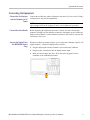
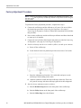
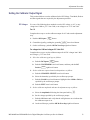
Navigating During Adjustments
Continue. Once you have set the c alibrator output signal that is specified
on the oscilloscope screen, push the OK Do Next Step side-bezel button to
proceed. Information about setting up the calibrator output signal is provided
after the Factory Adjustment Procedure. (See page 13, Setting the Calibrator
O
utput Signal.)
Go back. Push the Return to Previous Screen side-bezel button to go back
to the previous step. Push the button multiple times if you want to go back
multiple steps.
Abort. Push the Menu Off front-panel button on the oscilloscope to cancel the
procedure at any time. This causes the oscilloscope to revert to the previous
calibration constants. The last factory calibration date will not be updated.
8 MSO4000B and DPO4000B Series Digital Phosphor Oscilloscopes Service Manual
Page is loading ...
Page is loading ...
Page is loading ...
Page is loading ...
Page is loading ...
Page is loading ...
Page is loading ...
Page is loading ...
Page is loading ...
Page is loading ...
Page is loading ...
Page is loading ...
Page is loading ...
Page is loading ...
Page is loading ...
Page is loading ...
Page is loading ...
Page is loading ...
Page is loading ...
Page is loading ...
Page is loading ...
Page is loading ...
Page is loading ...
Page is loading ...
Page is loading ...
Page is loading ...
Page is loading ...
Page is loading ...
Page is loading ...
Page is loading ...
Page is loading ...
Page is loading ...
Page is loading ...
-
 1
1
-
 2
2
-
 3
3
-
 4
4
-
 5
5
-
 6
6
-
 7
7
-
 8
8
-
 9
9
-
 10
10
-
 11
11
-
 12
12
-
 13
13
-
 14
14
-
 15
15
-
 16
16
-
 17
17
-
 18
18
-
 19
19
-
 20
20
-
 21
21
-
 22
22
-
 23
23
-
 24
24
-
 25
25
-
 26
26
-
 27
27
-
 28
28
-
 29
29
-
 30
30
-
 31
31
-
 32
32
-
 33
33
-
 34
34
-
 35
35
-
 36
36
-
 37
37
-
 38
38
-
 39
39
-
 40
40
-
 41
41
-
 42
42
-
 43
43
-
 44
44
-
 45
45
-
 46
46
-
 47
47
-
 48
48
-
 49
49
-
 50
50
-
 51
51
-
 52
52
-
 53
53


Ask a question and I''ll find the answer in the document
Finding information in a document is now easier with AI
Related papers
-
Tektronix DPO4102B-L Technical Reference
-
Tektronix TBS1000C Series User manual
-
Tektronix DPO4000B Series User manual
-
-
Tektronix MDO3000 Series Program Manual
-
-
Tektronix AFG2021 User manual
-
Tektronix MSO5204B Installation
-
-
Other documents
-
ifrogz iPod Touch 2G & 3G Luxe Lean User manual
-
Zebra MC17 Owner's manual
-
Wolf 822193 Installation guide
-
Fluke 9500B User Handbook Manual
-
Fluke Calibration 9500B User guide
-
-
-
-
-
LeCroy LabMaster 10 Zi-A User manual