Page is loading ...

Motors | Automation | Energy | Transmission & Distribution | Coatings
Soft-Starter
SSW7000
User’s Manual


User’s Manual
Series:
SS
W
7000
Language
:
English
Document Number: 10001461783 / 08
Publication Data: 11/2019

Summary of Revisions

Summary of Revisions
The table describes the revisions made to this manual.
Revision
Description
Chapter
1
First edition
-
2
Correction of table 8.1
8
3
Section update 10.3.1 – safe sectioning
10
D.O.L. starting description – section 10.4
10
4
SSW7000C Description
3, 5, 6 and 9
5
General Revision
1 - 10
6
Inclusion of the 500A and 600A models
3
PFC description with capacitor discharge adjustment
3
Change of D.O.L. mode operation
10
7
Inclusion of the 6,9 kV models – SSW7000C
3, 5, 6 and 9
8
Inclusion of the 13,8 kV models – SSW7000D
3, 5, 6 and 9

Contents
1 SAFETY INSTRUCTIONS ................................................................... 1-1
1.1. SAFETY WARNINGS IN THE MANUAL ......................................................................................... 1-1
1.2. SAFETY WARNINGS IN THE PRODUCT ...................................................................................... 1-1
1.3. PRELIMINARY RECOMMENDATIONS ......................................................................................... 1-2
2 ABOUT THE MANUAL ....................................................................... 2-1
2.1. TERMS AND DEFINITIONS ............................................................................................................ 2-1
2.1.1. Terms and Definitions Used in the Manual ....................................................................... 2-1
3 ABOUT THE SSW7000 ....................................................................... 3-1
3.1. MAIN CHARACTERISTICS............................................................................................................. 3-2
3.1.1. Disconnect Switch .......................................................................................................... 3-2
3.1.2. Fuses ............................................................................................................................. 3-2
3.1.3. Protection Relay ............................................................................................................. 3-2
3.1.4. Line Contactor ................................................................................................................ 3-2
3.1.5. Line Circuit Breaker ........................................................................................................ 3-2
3.1.6. Bypass Contactor ........................................................................................................... 3-3
3.1.7. Bypass Circuit Breaker .................................................................................................... 3-3
3.1.8. Power Arms .................................................................................................................... 3-3
3.1.9. Control ........................................................................................................................... 3-4
3.1.10. Motor thermal Protection ............................................................................................. 3-4
3.1.11. Tests ........................................................................................................................... 3-4
3.1.12. Ground Fault Protection ............................................................................................... 3-4
3.1.13. Command for Power Factor Correction ........................................................................ 3-5
3.2. SSW7000 IDENTIFICATION LABEL .............................................................................................. 3-7
3.3. HOW TO SPECIFY THE SSW7000 MODEL (SMART CODE) ....................................................... 3-8
3.4. RECEIVING AND STORAGE .......................................................................................................... 3-8
3.4.1. Unpacking ...................................................................................................................... 3-9
3.4.2. Panel and Power Arm Storage ...................................................................................... 3-10
4 HMI ....................................................................................................... 4-1
4.1. BATTERY ......................................................................................................................................... 4-1
4.2. HMI CABLE ..................................................................................................................................... 4-1
5 INSTALLATION AND CONNECTION ................................................ 5-1
5.1. MECHANICAL INSTALLATION ...................................................................................................... 5-1
5.1.1. Environmental Conditions ................................................................................................ 5-1
5.1.2. Dimensions with Package ............................................................................................... 5-1
5.1.3. Panel and Arm Dimensions ............................................................................................. 5-3
5.1.4. Handling Recommendations ........................................................................................... 5-8
5.1.5. Hoisting .......................................................................................................................... 5-8
5.1.6. Moving ........................................................................................................................... 5-8
5.1.7. Positioning and Mounting ................................................................................................ 5-9
5.1.8. Medium Voltage Compartment ...................................................................................... 5-12
5.1.9. Low Voltage Compartment ............................................................................................ 5-13
5.1.10. Power Cable Entry ..................................................................................................... 5-14
5.1.11. Control Cable Entry ................................................................................................... 5-15
5.1.12. Power Arm Insertion .................................................................................................. 5-16

Contents
5.2. ELECTRICAL INSTALLATION ..................................................................................................... 5-17
5.2.1. Power Arm Electrical and Fiber Optic Connections ........................................................ 5-17
5.2.2. SSW7000 Simplified Block Diagram .............................................................................. 5-23
5.2.3. Location of the Power and Grounding Connections ....................................................... 5-24
5.2.4. Recommended Power and Grounding Cables ............................................................... 5-26
5.2.5. Fuses ........................................................................................................................... 5-27
5.2.6. Connection of the Power Supply to the SSW7000 ......................................................... 5-28
5.2.7. Power Supply Short Circuit Rating ................................................................................ 5-28
5.2.8. Motor Connection......................................................................................................... 5-28
5.2.9. Grounding Connection.................................................................................................. 5-29
5.2.10. User Signal and Control Connections ........................................................................ 5-30
5.2.11. Auxiliary Low Voltage Supply Connection .................................................................. 5-34
6 INTERNAL CONNECTIONS............................................................... 6-1
6.1. SSW7000 ELECTRONIC BOARDS ................................................................................................ 6-1
6.1.1. CC11 Board ................................................................................................................... 6-1
6.1.2. CSM Board Connections ................................................................................................ 6-2
6.1.3. CSMGA Board Connections ........................................................................................... 6-3
6.1.4. FSMT Board Connections ............................................................................................... 6-4
6.1.5. Power Arm Internal Connections ..................................................................................... 6-5
6.1.6. Connections between the CSM Board and the TF Transformer ........................................ 6-7
6.1.7. Connections between the Low Voltage and the Medium Voltage Controls ....................... 6-8
7 FIRST ENERGIZATION ...................................................................... 7-1
7.1. SSW7000 OPERATION VERIFICATION ........................................................................................ 7-1
7.1.1. Test without Three-phase Voltage ................................................................................... 7-2
7.1.2. Test with Medium Voltage ............................................................................................... 7-2
7.1.3. Test with Low Voltage .................................................................................................... 7-3
7.2. COMMISSIONING .......................................................................................................................... 7-4
7.3. CONNECTION TO A PC ................................................................................................................. 7-5
7.4. FLASH MEMORY MODULE ........................................................................................................... 7-5
8 ACCESSORIES ................................................................................... 8-1
9 TECHNICAL SPECIFICATIONS ........................................................ 9-1
9.1. POWER DATA ................................................................................................................................. 9-1
9.1.1. Operational Capacity ...................................................................................................... 9-1
9.2. CONTROL DATA ............................................................................................................................ 9-6
10 TROUBLESHOOTING AND MAINTENANCE ................................. 10-1
10.1. FAULT TRIPS AND ALARMS ................................................................................................... 10-1
10.2. MOST FREQUENT PROBLEMS ............................................................................................... 10-2
10.3. FAULTS ON THE FSMT BOARD .............................................................................................. 10-3
10.4. PREVENTIVE MAINTENANCE ................................................................................................. 10-4
10.4.1. SSW7000 Disconnection Sequence .......................................................................... 10-5
10.5. DIRECT ONLINE START – DOL ............................................................................................... 10-6
10.6. DATA FOR CONTACT WITH THE TECHNICAL SUPPORT ................................................... 10-6

Contents

SSW7000 | 1-1
Safety Instructions
1 SAFETY INSTRUCTIONS
This manual contains the information necessary for the correct use of the SSW7000.
It has been written to be used by qualified personnel with suitable training or technical qualification for operating
this type of equipment.
1.1. SAFETY WARNINGS IN THE MANUAL
The following safety notices are used in the manual:
DANGER!
The procedures recommended in this warning have the purpose of protecting the user against
death, serious injuries and considerable material damage.
ATTENTION!
The procedures recommended in this warning have the purpose of avoiding material damage.
NOTE!
The information mentioned in this warning is important for the proper understanding and good
operation of the product.
1.2. SAFETY WARNINGS IN THE PRODUCT
The following symbols are attached to the product, serving as safety notices:
High voltages are present
Components sensitive to electrostatic discharge.
Do not touch them
Mandatory connection to the protective earth (PE).
Connection of the shield to the ground.

SSW7000 | 1-2
Safety Instructions
1.3. PRELIMINARY RECOMMENDATIONS
DANGER!
Only qualified personnel familiar with the SSW7000 soft-
starter and associated equipment should
plan or implement the installation, start-up and subsequent maintenance of this equipment.
These personnel must follow all the safety instructions included in this manual and/or defined by
local regulations.
Failure to comply with these instructions may result in life threatening and/or equipment damage
NOTES!
For the purposes of this manual, qualified personnel are those trained to be able to:
1. Install, ground, energize and operate the SSW7000 according to this manual and the effective
legal safety procedures
2. Use protective equipment according to the established standards.
3. Give first aid services.
DANGER!
Always disconnect the input power before touching any electrical component associated to the
SSW7000. Follow the SSW7000 disconnection sequence, according to the item 10.4.1 - SSW7000
Disconnection Sequence.
High voltages and rotating parts (fans, if installed) may be present on the SSW7000 even after shut
down or power disconnection. Wait at least 3 minutes for the complete discharge of the capacitors
and the stopping of the fans.
Always connect the equipment frame to the protective earth (PE) at the suitable connection point.
ATTENTION!
Electronic boards have components sensitive to electrostatic discharges. Do not touch directly on
components or connectors. If necessary, touch the grounded metallic frame before or use an
adequate grounded wrist strap.
Do not perform any high pot tests with the SSW7000!
If it is necessary, consult WEG.
NOTE!
Soft-starters may interfere with other electronic equipments. In order to minimize these effects, take
the precautions recommended in the chapter 5 - Installation and Connection.
NOTE!
Read the user's manual completely before installing or operating the SSW7000.

SSW7000 | 2-1
About the Manual
2 ABOUT THE MANUAL
This manual presents the necessary information for the installation and commissioning, as well as the product
main technical characteristics, and how to troubleshoot the SSW7000 most common problems.
This manual must be used together with the SSW7000 programming manual.
ATENÇÃO!
The operation of this equipment requires installation instructions and detailed operation provided in
the user's manual, programming manual and communication manuals. The user's manual and the
programming manual are supplied in a hard copy together with the soft-starter. The us
er guides
are also provided in a hard copy along with the accessories. The other manuals can be downloaded
from the WEG website at - www.weg.net.
In order to obtain more information on the accessories and its operation, refer to the following manuals:
RS-232/RS-485 Serial Communication Manual.
Anybus-CC Communication Manual.
SoftPLC Manual
Reproduction of this manual content is prohibited, as a whole or in parts, without written permission from WEG.
2.1. TERMS AND DEFINITIONS
2.1.1. Terms and Definitions Used in the Manual
Amp,
A:
ampere
AC:
alternating current.
DC:
direct current.
DOL:
Direct Online start.
°C:
c
e
l
s
i
us degrees
.
HMI
: Human-Machine Interface; it is the device that allows the control of the motor, the visualization and the
modification of the SSW7000 parameters. It presents keys for commanding the motor, navigation keys and a
graphic LCD display.
hp:
“Horse Power” = 746 Watts (power measurement unit, normally used to indicate the mechanical power of
electric motors).
Hz:
hertz.
kg:
kilogram
= 1000 gramas.
kHz:
kilohertz
= 1000 hertz.
kV:
kilovolts
= 1000
v
o
l
t
s
.
mA:
miliampere
= 0.001 ampères.

SSW7000 | 2-2
About the Manual
min:
m
i
nu
t
e.
ms:
milisecond
= 0.001 segundos.
Nm:
newton meter;
torque measurement unit
.
OEM:
Original Equipment Manufacturer
.
Ω:
o
hm.
PE:
Protective
Earth.
PFC:
Power Factor Correction.
rms: “Root mean square”;
effective value
rpm: revolutions per minute, speed measurement unit.
s:
second.
UCBT:
Low voltage control unit
.
UC
M
T
:
Medium voltage control unit
.
USB:
“Universal Serial
BUS”;
it is a type of connection in the perspective of the
“Plug
and
P
l
a
y
” concept
.
V:
v
o
l
t
s
.

SSW7000 | 3-1
About the SSW7000
3 ABOUT THE SSW7000
The “Soft-Starter WEG 7000” is a high performance product that allows the starting/stopping control and
protection of medium voltage three-phase induction motors, thus preventing mechanical shocks ant the load,
current peaks in the supply line and damage to the motor.
Figure 3.1: General block diagram of SSW7000 frames A, B and C.
Figure 3.2: General block diagram of SSW7000 frame D.
NOTE!
The capacitor bank for power factor correction is provided in an additional column coupled to
the SSW7000

SSW7000 | 3-2
About the SSW7000
3.1. MAIN CHARACTERISTICS
The soft-starter SSW7000 has four panel versions: two IP41 versions, one IP54 version and one NEMA version.
The NEMA and IP54 are compacts versions – SSW7000C, 36” wide. The operation is the same for all versions.
The specific differences among the versions will be detailed in this manual.
3.1.1. Disconnect Switch
The SSW7000 with frames A, B and C have a medium voltage input disconnect switch that allows the electrical
disconnection of the internal circuit of the SSW7000 from the power supply.
This disconnect switch is interlocked with the panel door, so that the door can only be opened when the
disconnect switch is also open. When open, the connections on the upper side of the fuses are grounded.
DANGER!
Even with the disconnect switch open, voltage may still be present on the side of medium voltage
power supply of the disconnect switch. When maintenance is required on the medium voltage side
of the disconnect switch, the medium voltage power supply must be disconnected and grounded
in a point before the SSW7000.
DANGER!
The SSW7000 has another power supply for the low voltage control. Make sure there is no voltage
before touching any component
3.1.2. Fuses
The SSW7000 with frames A, B and C have R-type medium voltage fuses against short circuit in the panel, motor
and cables up to the motor.
3.1.3. Protection Relay
The SSW7000 with frame D has a protection relay to detect overcurrent and short circuit in the panel, motor and
cables up to the motor.
3.1.4. Line Contactor
The SSW7000 with frames A, B and C have a line vacuum contactor with utilization category AC-3, which makes
it possible to disconnect the SSW7000 power section whenever the motor is deactivated.
The line contactor is driven by the SSW7000 control electronics.
3.1.5. Line Circuit Breaker
The SSW7000 with frame D has a removable vacuum circuit breaker which capacity to close and interrupt short-
circuit currents, complying with IEC 62271-100 and with the standards of the main industrialized countries.
This circuit breaker is sized to withstand direct on line starting and the SSW7000 rated current at full load. It also
allows the implementation of a direct on line starting logic.
The line circuit breaker is driven by the SSW7000 control electronics.

SSW7000 | 3-3
About the SSW7000
3.1.6. Bypass Contactor
The SSW7000 with frames A, B and C have a vacuum contactor with utilization category AC-3, which makes it
possible to bypass the power arms after starting the motor. This function allows energy saving by eliminating
losses on the SCRs during the motor full operating duty and it also eliminates the necessity of using fans for the
operation of the SSW7000 in its rated start operation duty, which is specified in the section 9.1 – Power Data.
This contactor is sized to withstand direct on line starting and the SSW7000 rated current at full load. It also allows
the implementation of a direct on line starting logic.
The bypass contactor is driven by the SSW7000 control electronics.
3.1.7. Bypass Circuit Breaker
The SSW7000 with frame D has a vacuum circuit breaker which makes it possible to bypass the power arms after
starting the motor. This function allows energy saving by eliminating losses on the SCRs during the motor full
operating duty and it also eliminates the necessity of using fans for the operation of the SSW7000 in its rated start
operation duty, which is specified in the section 9.1 – Power Data.
This circuit breaker is sized to withstand direct on line starting and the SSW7000 rated current at full load. It also
allows the implementation of a direct on line starting logic.
The bypass circuit breaker is driven by the SSW7000 control electronics.
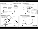
3.1.8. Power Arms
The SSW7000 power arms are assembled as modules with wheels that facilitate their installation and replacement
during maintenance. For the SSW7000C version, the power arms don’t have wheels and are attached to the back
of the panel.
(a) SSW7000A (b) SSW7000C
Figure 3.3: Power Arms
Each arm is comprises the SCRs, heatsinks, snubbers, supply transformers and firing boards. The firing
commands and the temperature readings are performed through fiber optic cables.
If it is necessary to increase the start duty of the SSW7000, increasing the number of starts per hour, for instance,
it is possible to install fans on the power arms. In such case, refer to the manufacturer.

SSW7000 | 3-4
About the SSW7000
3.1.9. Control
The SSW7000 control is implemented using two electronic control boards, isolated from each other through fiber
optic cables.
The C1 (CC11) control board is responsible for all the user access means: HMI, analog and digital inputs and
outputs, communication accessories, PT100 input and SoftPLC. It presents the possibility of firmware update
either via USB communication or via flash memory.
The C2 (CSM) control board is responsible for the motor control, the firing signals, the voltage and current
readings, and the synchronism. It is mounted in the medium voltage compartment and it does not allow direct
access to the user. The board firmware can be updated via USB communication.
3.1.10. Motor thermal Protection
Besides the possibility of using overload protection on the motor by means of preset thermal class, the SSW7000
has an eight channel PT100 input accessory (IOE-04 module), which allows monitoring the motor winding and
bearing temperatures.
The advantage of this module is the possibility of using the motor overload protection combined with the PT100
temperature measurements. Besides, these temperature measurements are also available on the HMI and
through network communication.
The fault and alarm levels of the motor thermal protection through the motor PT100 sensors can be totally
programmed. For further details, refer to sections 15.5 - Motor Thermal Protection and 15.6 - Motor Thermal
Class Protection, of the programming manual.
3.1.11. Tests
The SSW7000 has a test routine with the purpose of verifying the main panel connections. For more details, refer
to the section 7.1- SSW7000 Operation Verification in this manual and to the section 14.2 - Test Mode in the
SSW7000 programming manual.
There is also the possibility of performing test with low voltage; however, it becomes necessary to change the
voltage reading connections, as well as the SSW7000 parameterization (P0296).
3.1.12. Ground Fault Protection
The SSW7000 has two ground fault detection methods. One by neutral to ground voltage measurement (in the
standard panel) for isolated networks, and another by ground fault current measurement (the current transformer
is optional).
Figure 3.4: Ground fault detection by voltage
NOTE!
The ground fault by voltage detected by the SSW7000 may have occurred in any point of the
power supply system from the transformer to the motor.
The ground fault protection by voltage has the advantage that the SSW7000 also detects the ground fault when
the ground fault current does not pass through the SSW7000.

SSW7000 | 3-5
About the SSW7000
Figure 3.5: Ground fault detection by current.
3.1.13. Command for Power Factor Correction
NOTE!
The capacitor bank for power factor correction is provided in an additional column coupled to
the SSW7000
DANGER!
Power factor correction capacitors must never be installed at the SSW7000 output
(U / 2T1, V / 4T2 and W / 6T3).
NOTE!
The current carrying capacity of digital outputs DO1, DO2 and DO3 is 1A, as described in 9.2
Control Data.
Control for a SSW7000
The SSW7000 can control the motor power factor correction (PFC) capacitor bank directly through a digital output
(DO1, DO2 or DO3) programmed for “PFC Control”. The digital output will then be activated after the motor starts
and after the bypass contactor closes, thus preventing the capacitor bank from being activated with the motor
turned off or during the motor start or stop.
Figure 3.6: Connection to PFC Control for a SSW7000C

SSW7000 | 3-6
About the SSW7000
Control for Multiple SSW7000
Multiple SSW7000 may be connected in parallel, sharing the same power supply transformer.
Figure 3.7: Parallel connections between "n" SSW7000C
In order to automatically control the motor power factor correction (PFC) capacitor banks for multiple SSW7000,
a digital input (DI1, DI2, DI3, DI4, DI5 or DI6) must be set to “PFC Lock”, a digital output (DO1, DO2 or DO3) must
be set to “PFC Control”, and another digital output must be set to “PFC Lock”.
The electrical connections between the CC11 control boards of the Soft Starters must be done so that all the
digital inputs receive the signal from the digital output “PFC Lock”, as shown in the example of figure 3.8. In this
example, digital outputs DO1 and DO2 and digital input DI5 were used. The parameters configured in the example
are “15=PFC Lock” (DO1), “14=PFC Control” (DO2) and “16=PFC Lock” (DI5).
Figure 3.8 : Connection to PFC Controls for Multiple SSW7000 (example).

SSW7000 | 3-7
About the SSW7000
The start of multiple SSW7000 is done sequentially and/or simultaneously. For the simultaneous start condition
of two or more SSW7000, the PFC capacitor banks will be enabled at the same time after the start of the last
motor. As described by IEC 60871-1, the peak value of the capacitor bank inrush current must not exceed 100
times the value of the rated current. If the Inrush current is higher, a reactance must be installed in series with
each capacitor bank. The reactance will reduce the peak current and attenuate the effect of transient overvoltage.
Discharge of the Power Factor Correction Capacitors
When the power factor correction capacitor is disconnected from the line, a residual voltage remains on it. When
the capacitor is reconnected, such residual voltage can cause an inrush current of up to twice the value obtained
when the capacitor is discharged during reconnection, thus reducing its useful life. In order to prevent the increase
of the inrush current, the capacitors must be internally equipped with a discharge device able to reduce the
residual voltage to a value close to zero after its disconnection.
Parameter P0280 - CAPACITOR DISCHARGE TIME defines the time the SSW7000 waits for the discharge of the
power factor correction capacitors so as to allow a new connection. P0280 can be programmed with values
between 60 to 600 seconds, and the standard value is 300 seconds (NBR5282 standard).
3.2. SSW7000 IDENTIFICATION LABEL
The SSW7000 identification label is affixed inside the product cabinet. This label contains important information on
the SSW7000.
Figure 3.9. Identification label of SSW7000 (example).
Other important information can be found on the label of the Power Arms.
Figure 3.10 Identification label of Power Arm (example).
Nominal Voltage
SSW7000 Model
WEG Part Number
Nominal Current
Manufacturing date
(15 corresponds to
week and H to year)
Serial Number

SSW7000 | 3-8
About the SSW7000
3.3. HOW TO SPECIFY THE SSW7000 MODEL (SMART CODE)
In order to specify the correct model of WEG Soft-Starter, use the product smart code. It is composed of
several parts, which are described below:
SSW7000
A
180
T
4
11
41
1
2
3
4
5
6
7
Table 3.1. Smart Code
1
2
3
4
5
6
7
8
9
10
11
Model
Frame
Rated
Current
Number
of Phases
Rated Voltage
Auxiliary
Power
Supply
Degree of
Protection
Blower
Cooled
Special
Hardware
Special
Software
Market
SSW7000 A = Panel 070 = 70A T = 2 = up to 2.3kV 11 = 110V 41 = IP41 Blank = Blank = Blank = Blank =
= Soft- Frame 180 = 180A
Three-
phase
4 = up to 4.16kV 22 = 220V Standard Standard Standard Global
Starter A 300 = 300A 6 = up to 6.9kV F =
WEG 360 = 360A
Blower-
Cooled
series B = Panel 500 = 500A T = 2 = up to 2.3kV 11 = 110V 41 = IP41 Blank = Blank = Blank = Blank =
7000 Frame 600 = 600A
Three-
phase
4 = up to 4.16kV 22 = 220V
N2 =
NEMA 12
Standard Standard Standard Global
B
6 = up to 6.9kV
F =
(2 columns)
Blower-
Cooled
C = Panel 125 = 125A T = 2 = up to 2.3kV 11 = 110V 54 = IP54 Blank = Blank = Blank = Blank =
Compact 250 = 250A
Three-
phase
4 = up to 4.16kV 22 = 220V
N2 =
NEMA 12
Standard Standard Standard Global
359 = 360A 6 = up to 6.9kV F =
Blower-
Cooled
D = Panel 180 = 180A T = 9= up to 13,8kV 11 = 110V 41 = IP41 Blank = Blank = Blank = Blank =
Frame 300 = 300A
Three-
phase
22 = 220V Standard Standard Standard Global
D
400 = 400A
F =
500 = 500A
(MTW)
600 = 600A
Blower-
Cooled
3.4. RECEIVING AND STORAGE
The standard SSW7000 is supplied with the power arms separated from the panel and packed individually.
The SSW7000 panel is supplied in a package composed by cardboard, plastic and wood.
Wood and polystyrene wedges compose the power arm package. There is an identification label outside this
package, which is identical to the one affixed to the power arms. Confront the content of this label with the
purchase order.
The contents of the packages should be verified on product receiving.
NOTES!
If any component is found damaged, it is recommended to:
1. Stop the package opening immediately.
2. Contact the carrier and fill in a format complaint of the problem found.
3. Take pictures of the damaged parts/components.
4. Contact your WEG representative or WEG service.
Guidance for handling, transportation, mechanical and electric installation of the product, is presented in the
chapter 5 - Installation and Connection
/