Page is loading ...

Super
Combination Boilers
installation and servicing instructions


CONTENTS
1 TECHNICAL FEATURES AND DIMENSIONS
1.1 INTRODUCTION . . . . . . . . . . . . . . . . . . . . . . . . . . . . . . . . . . . . . . . . . . . . . . . . . . . . . . . . . . . . . . 1
1.2 DIMENSIONAL DETAILS
1.3 GENERAL DATA . . . . . . . . . . . . . . . . . . . . . . . . . . . . . . . . . . . . . . . . . . . . . . . . . . . . . . . . . . . . . . 2
1.4 HYDRAULIC CIRCUIT . . . . . . . . . . . . . . . . . . . . . . . . . . . . . . . . . . . . . . . . . . . . . . . . . . . . . . . . . . 3
2 GENERAL REQUIREMENTS FOR INSTALLATION
2.1 STATUTORY REQUIREMENTS . . . . . . . . . . . . . . . . . . . . . . . . . . . . . . . . . . . . . . . . . . . . . . . . . . . . . 4
2.2 BOILER POSITION
2.3 FLUE TERMINAL POSITION
2.4 VENTILATION REQUIREMENTS . . . . . . . . . . . . . . . . . . . . . . . . . . . . . . . . . . . . . . . . . . . . . . . . . . . . 5
2.5 GAS SUPPLY
2.6 ELECTRICITY SUPPLY
2.7 EXTERNAL CONTROLS
2.8 WATER SYSTEMS - GENERAL
2.9 REQUIREMENTS FOR SEALED WATER SYSTEMS
2.10 D.H.W. SYSTEMS . . . . . . . . . . . . . . . . . . . . . . . . . . . . . . . . . . . . . . . . . . . . . . . . . . . . . . . . . . . . . 7
3 INSTALLING THE BOILER
3.1 UNPACKING THE BOILER . . . . . . . . . . . . . . . . . . . . . . . . . . . . . . . . . . . . . . . . . . . . . . . . . . . . . . . . 9
3.2 FIXING THE WALL MOUNTING BRACKET
3.3 HANGING THE BOILER . . . . . . . . . . . . . . . . . . . . . . . . . . . . . . . . . . . . . . . . . . . . . . . . . . . . . . . . . 10
3.4 FLUE AND TERMINAL PREPARATION
3.5 FLUE AND TERMINAL INSTALLATION . . . . . . . . . . . . . . . . . . . . . . . . . . . . . . . . . . . . . . . . . . . . . . . 11
3.6 WATER CONNECTIONS . . . . . . . . . . . . . . . . . . . . . . . . . . . . . . . . . . . . . . . . . . . . . . . . . . . . . . . . . 12
3.7 GAS CONNECTIONS . . . . . . . . . . . . . . . . . . . . . . . . . . . . . . . . . . . . . . . . . . . . . . . . . . . . . . . . . . . 13
3.8 SAFETY VALVE CONNECTION
3.9 WIRING INSTRUCTIONS
4 COMMISSIONING AND TESTING
4.1 FILLING THE WATER SYSTEM . . . . . . . . . . . . . . . . . . . . . . . . . . . . . . . . . . . . . . . . . . . . . . . . . . . . . 14
4.2 COMMISSIONING THE BOILER
4.3 SETTING THE C.H. INPUT
4.4 SETTING THE D.H.W. FLOWRATE . . . . . . . . . . . . . . . . . . . . . . . . . . . . . . . . . . . . . . . . . . . . . . . . . . 15
4.5 FINAL CHECKS
4.6 USER’S INSTRUCTIONS
5 ROUTINE SERVICING INSTRUCTIONS
5.1 MAIN BURNER ASSEMBLY . . . . . . . . . . . . . . . . . . . . . . . . . . . . . . . . . . . . . . . . . . . . . . . . . . . . . . . 16
5.2 PILOT ASSEMBLY
5.3 FAN ASSEMBLY
5.4 HEAT EXCHANGER . . . . . . . . . . . . . . . . . . . . . . . . . . . . . . . . . . . . . . . . . . . . . . . . . . . . . . . . . . . . 17
5.5 RE-ASSEMBLY
5.6 RE-COMMISSIONING

6 FAULT FINDING
6.1 EARTH CONTINUITY CHECK . . . . . . . . . . . . . . . . . . . . . . . . . . . . . . . . . . . . . . . . . . . . . . . . . . . . . 18
6.2 SHORT CIRCUIT CHECK
6.3 POLARITY CHECK
6.4 RESISTANCE TO EARTH CHECK
6.5 C.H. MODE - FAULT FINDING . . . . . . . . . . . . . . . . . . . . . . . . . . . . . . . . . . . . . . . . . . . . . . . . . . . . 19
6.6 D.H.W. MODE - FAULT FINDING . . . . . . . . . . . . . . . . . . . . . . . . . . . . . . . . . . . . . . . . . . . . . . . . . . . 20
7 INTERNAL WIRING DIAGRAMS AND VIEWS
7.1 FUNCTIONAL FLOW WIRING DIAGRAM . . . . . . . . . . . . . . . . . . . . . . . . . . . . . . . . . . . . . . . . . . . . . 21
7.2 ILLUSTRATED WIRING DIAGRAM . . . . . . . . . . . . . . . . . . . . . . . . . . . . . . . . . . . . . . . . . . . . . . . . . . 22
7.3 INTERNAL VIEW “SUPER 90” . . . . . . . . . . . . . . . . . . . . . . . . . . . . . . . . . . . . . . . . . . . . . . . . . . . . . 23
7.4 INTERNAL VIEW “SUPER 102” . . . . . . . . . . . . . . . . . . . . . . . . . . . . . . . . . . . . . . . . . . . . . . . . . . . . 24
8 REPLACEMENT OF PARTS
8.1 HEAT EXCHANGER . . . . . . . . . . . . . . . . . . . . . . . . . . . . . . . . . . . . . . . . . . . . . . . . . . . . . . . . . . . . 25
8.2 COMBUSTION CHAMBER INSULATION
8.3 FAN ASSEMBLY
8.4 MAIN BURNER
8.5 PILOT BURNER ASSEMBLY AND ELECTRODE
8.6 GAS VALVE . . . . . . . . . . . . . . . . . . . . . . . . . . . . . . . . . . . . . . . . . . . . . . . . . . . . . . . . . . . . . . . . . 26
8.7 PRESSURE SWITCH
8.8 LIMIT THERMOSTAT
8.9 OVERHEAT THERMOSTAT . . . . . . . . . . . . . . . . . . . . . . . . . . . . . . . . . . . . . . . . . . . . . . . . . . . . . . . 27
8.10 THERMISTOR - C.H. OR D.H.W.
8.11 IGNITION PCB
8.12 DRIVER PCB
8.13 PUMP
8.14 D.H.W. HEAT EXCHANGER
8.15 DIVERTOR VALVE - COMPLETE
8.16 DIVERTOR VALVE - MICROSWITCH ASSEMBLY . . . . . . . . . . . . . . . . . . . . . . . . . . . . . . . . . . . . . . . . 28
8.17 C.H. EXPANSION VESSEL
8.18 SUMMER/WINTER SWITCH
8.19 PRESSURE GAUGE
8.20 SAFETY VALVE
8.21 AUTOMATIC AIR VENT
8.22 VIEWING WINDOW
8.23 D.H.W. EXPANSION VESSEL - IF FITTED . . . . . . . . . . . . . . . . . . . . . . . . . . . . . . . . . . . . . . . . . . . . . . 29
8.24 TIME CLOCK
8.25 TIME CLOCK OVERRIDE SWITCH
8.26 FROST THERMOSTAT
8.27 TEMPERATURE GAUGE
9 SHORT LIST OF PARTS

1.1 INTRODUCTION
The Sime “SUPER” family is a fully automatic, wall moun-
ted, room sealed, fan assisted range of combination boilers.
The above appliances can be fuelled with natural gas and
provide central heating and instantaneous production of
D.H.W. The heat output varied according to the demand on
both D.H.W. and C.H modes.
The appliance is supplied with a concentric air and flue duct
suitable for flue lengths of up to 0.83 m (32
1
⁄2 in) although
extension duct kits are available and may be used up to a
flue length of 2.4 m (94
1
⁄2 in). The combined flue and air
duct can exit the boiler from either side or from the rear of
the appliance. A vertical extension and additional flue elbow
may be fitted.
The boiler is designed for use with sealed primary water
systems and is supplied fully assembled and equipped with
complete valve packs; a D.H.W. expansion vessel is available
upon request on “90” model.
If the wall thickness is less than 0.5 m (19 in) the appliance
can be installed from inside the room without access to the
external wall although a wall liner is required. This is available
as an optional extra, and full details are given in section 3.
All boilers may be used with a 24 V room thermostat. A 240
V room thermostat may be fitted if a 24 V model is not avai-
lable, but its sensitivity will be reduced (refer to section 2.7
for details).
The Sime “SUPER” features an attractive white enamelled
casing with a moulded white plastic control box and facia
panel.
1
1 TECHNICAL FEATURES AND DIMENSIONS
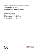
TABLE 2 - Minimum clearances
mm in
ABOVE THE APPLIANCE CASING 200 8
AT THE R.H.S. 90 3
1
⁄2
AT THE L.H.S. 30 1
1
⁄4
BELOW THE APPLIANCE CASING 200 8
IN FRONT OF THE APPLIANCE 450 18
TABLE 1 - Connections
R C.H. return 22 mm Compression
M C.H. flow 22 mm Compression
G Gas connection
1
⁄2 in Bsp
E Cold water 15 mm Compression
U Hot water 15 mm Compression
S Safety valve 15 mm Copper
1.2 DIMENSIONAL DETAILS
Fig. 1
L = 450 mm (“SUPER 90”)
500 mm (“SUPER 102”)
P = 225 mm (“SUPER 90”)
295 mm (“SUPER 102”)

2
1.3 GENERAL DATA
TABLE 4 - General Specification
SUPER 90 SUPER 102
Main burner injectors No off 13 15
Dia mm 1.3 1.3
Water capacity l (gal) 2.1 (0.5) 2.6 (0.6)
Minimum water flow C.H. l/min (gal/min) 22.0 (5.0) 28.0 (6.2)
D.H.W. l/min (gal/min) 2.1 (0.5) 2.1 (0.5)
D.H.W. flow rate 30°C l/min (gal/min) 12.6 (2.8) 14.1 (3.1)
at a temp. rise of 35°C l/min (gal/min) 10.8 (2.4) 12.1 (2.7)
Static head Min. bar (psi) 0.5 (7.3) 0.5 (7.3)
Max. bar (psi) 3.0 (43.5) 3.0 (43.5)
D.H.W. pressure Min. bar (psi) 0.9 (13.0) 0.9 (13.0)
Max. bar (psi) 7.0 (102) 7.0 (102)
Weight Empty kg (lb) 48 (106) 54 (120)
Max lift kg (lb) 45 (99) 51 (113)
Total (full) kg (lb) 50 (110) 56 (124)
Electrical supply 230 V - 50 Hz, Fused at 3 A
Internal fuses Line: F 1.6 A - P.C.B.: T 100 mA
Max. power consumption Watt 150 210
Max. gas consumpt. (G20) C.H. m
3
/h (ft
3
/h) 2.8 (99) 3.6 (120)
D.H.W. m
3
/h (ft
3
/h) 3.1 (109) 3.6 (120)
Max. working temperature °C (F) 85 (185) 85 (185)
Integral exp. vessel capacity l (gal) 7 (1.5) 7 (1.5)
TABLE 3a - Nominal boiler ratings (2 minutes after lighting) for “SUPER 90”
MODE OUTPUT INPUT (G.C.V.) BURNER PRESSURE
kW Btu/h kW Btu/h mbar inwg
CENTRAL HEATING RANGE 9.7 33,000 13.8 47,000 1.9 0.8
10.6 36,000 14.8 50,400 2.2 0.9
12.3 42,000 16.8 57,300 3.1 1.2
14.1 48,000 18.9 64,500 4.1 1.6
15.8 54,000 20.9 71,300 5.1 2.0
17.6 60,000 22.9 78,100 6.3 2.5
19.3 66,000 24.8 84,700 7.5 3.0
21.1 72,000 26.7 91,100 8.7 3.5
23.4 80,000 29.3 100,000 10.4 4.1
DOMESTIC HOT WATER Max. 26.4 90,000 32.6 111,200 12.9 5.2
Min. 8.8 30,000 12.5 42,800 1.5 0.6
TABLE 3b - Nominal boiler ratings (2 minutes after lighting) for “SUPER 102”
MODE OUTPUT INPUT (G.C.V.) BURNER PRESSURE
kW Btu/h kW Btu/h mbar inwg
CENTRAL HEATING RANGE 15.3 52,200 18.6 63,500 3.9 1.5
17.4 59,400 20.6 70,300 4.9 1.9
20.3 69,300 23.5 80,200 6.4 2.5
22.8 77,800 26.0 88,700 7.8 3.1
25.0 85,300 28.3 96,600 9.3 3.7
27.0 92,100 30.5 104,100 10.8 4.3
29.7 102,000 33.1 113,000 12.7 5.1
DOMESTIC HOT WATER Max. 29.7 102,000 33.1 113,000 12.7 5.1
Min. 10.5 35,800 13.0 44,300 2.0 0.8

3
TABLE 5a - Flue lenghts Subtract desired side clearances (if applicable) to determine available wall thickness.
Rear outlet L.H. side outlet R.H. side outlet
SUPER 90 mm in mm in mm in
STANDARD FLUE KIT 745 29
1
⁄4 690 27
1
⁄4 630 24
3
⁄4
WITH ONE EXTENSION KIT 1,560 61
1
⁄2 1,505 59
1
⁄4 1,445 56
3
⁄4
WITH TWO EXTENSION KITS 2,375 93
1
⁄2 2,320 91
1
⁄4 2,260 89
TABLE 5b - Flue lenghts Subtract desired side clearances (if applicable) to determine available wall thickness.
Rear outlet L.H. side outlet R.H. side outlet
SUPER 102 mm in mm in mm in
STANDARD FLUE KIT 745 29
1
⁄4 620 24
1
⁄2 650 25
1
⁄2
WITH ONE EXTENSION KIT 1,560 61
1
⁄2 1,435 56
1
⁄2 1,465 57
3
⁄4
WITH TWO EXTENSION KITS 2,375 93
1
⁄2 2,250 88
1
⁄2 2,280 89
3
⁄4
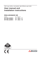
1.4 HYDRAULIC CIRCUIT
Fig. 2
KEY
1 Air pressure switch
2 Limit thermostat
3 Heat exchanger
4 Combustion chamber
5 Divertor valve
6 C.H. expansion vessel
7 D.H.W. heat exchanger (calorifier)
8 D.H.W. thermistor
9 D.H.W. expansion vessel
(only for for “SUPER 90”, upon request)
10 Multifunctional gas control
11 Pressure gauge
12 Safety valve
13 Drain cock
14 Circulating pump
15 Manual air vent
16 C.H. thermistor
17 Fan
18 Frost thermostat
19 Automatic air vent
20 Air separator
21 D.H.W. isolation valve
22 Gas cock
23 C.H. isolation valves

2.1 STATUTORY REQUIREMENTS
THE GAS SAFETY (INSTALLATION AND USE) REGULATIONS
1994.
It is the law that all gas appliances are installed by a compe-
tent person, in accordance with the above regulations.
Failure to install appliances correctly could lead to prosecu-
tion. It is in your own interest, and that of safety, to ensure
that the law is complied with. In addition to the above regu-
lations, this appliance must be installed in accordance with
the current IEE Wiring Regulations, Local Building
Regulations, the Building Standards (Scotland) and bye laws
of the local water undertaking. It should also be in accor-
dance with the relevant recommendations in the current edi-
tions of the following British Standards and Codes of
Practice: BS5449, BS5546, BS5440:1, BS5440:2, BS6798,
BS6891, and BG.DM2
IMPORTANT NOTE:
manufacturer’s instructions must NOT be taken in any
way as over-riding statutory obligations.
2.2 BOILER POSITION
In siting the combination boiler, the following limitations
MUST be observed:
– the boiler is not suitable for external installation. The
position selected for installation should be within the
building, unless otherwise protected by a suitable enclo-
sure, and MUST allow adequate space for installation,
servicing, and operation of the appliance, and for air
ciculation around it (section 2.4);
– this position MUST allow for a suitable flue termination
to be made. The combination boiler must be installed
on a flat vertical wall which is capable of supporting
the weight of the appliance, and any ancillary equip-
ment;
– if the combination boiler is to be fitted in a timber fra-
med building it should be fitted in accordance with the
British Gas Publication Guide for Gas Installations In Tim-
ber Frame Housing, Reference DM2. If in doubt, advice
must be sought from the Local Gas Region;
– if the appliance is installed in a room containing a bath
or shower, any electrical switch or control utilising mains
electricity must be so situated that it cannot be touched
by a person using the bath or shower. Attention is
drawn to the requirements of the current I.E.E. Wiring
Regulations, and in Scotland the electrical provisions of
the Building Regulations applicable in Scotland;
– a compartment used to enclose the appliance MUST be
designed and constructed specifically for this purpose.
An existing cupboard, or compartment, may be used
provided it is modified accordingly;
– where installation will be in an unusual location, special
procedures may be necessary. BS6798 gives detailed gui-
dance on this aspect.
2.3 FLUE TERMINAL POSITION
Detailed recommendations for flue installation are given in
BS5440:1. The following notes are for general guidance:
– the boiler MUST be installed so that the terminal is
exposed to the external air;
– it is important that the position of the terminal allows
free passage of air across it at all times;
– it is ESSENTIAL TO ENSURE, in practice that products of
combustion discharging from the terminal cannot re-
enter the building, or any other adjacent building,
through ventilators, windows, doors, other sources of
natural air infiltration, or forced ventilation/air condi-
tioning. If this does occur, the appliance MUST be tur-
ned OFF IMMEDIATELY and the Local Gas Region con-
sulted;
– the minimum acceptable dimensions from the terminal
to obstructions and ventilation openings are specified
in fig. 3;
2 GENERAL REQUIREMENTS FOR INSTALLATION
Fig. 3
Directly below an openable
window, air vent or any other
ventilation opening
Below guttering, drain pipes or
soil pipes
Below eaves, balconies or
carport roof
From vertical drain pipes or soil
pipes
From internal or external
corners
Above adjacent ground, roof
or balcony level
From a surface facing
the terminal
From a terminal facing
the terminal
From an opening in the carport
(eg door, window into
dwelling)
Vertically from a terminal on
the same wall
Horizontally from a terminal on
the same wall
Adjacent to opening
A
B
C/D
E
F
G
H
I
J
K
L
M
300 mm 12 in
75 mm 3 in
200 mm 8 in
75 mm 3 in
300 mm 12 in
300 mm 12 in
600 mm 24 in
1,200 mm 48 in
1,200 mm 48 in
1,500 mm 60 in
300 mm 12 in
300 mm 12 in
Terminal position Minimum spacing
TABLE 6
4

5
– if the terminal discharges into a pathway or passageway
check that combustion products will not cause nuisance
and that the terminal will not obstruct the passageway;
– where the lowest part of the terminal is fitted less than
2 m (78 in) above ground, above a balcony or above a
flat roof to which people have access, the terminal
MUST be protected by a purpose designed guard. Termi-
nal guards are available from Quinnell, Barrett, and
Quinnell, Old Kent Road, London. State model C2, (G.C.
Part No 382946);
– where the terminal is fitted within 850 mm (34 in) of a
plastic or painted gutter, or 450 mm (18 in) of painted
eaves, an aluminium shield at least 1,500 mm (59 in)
long must be fitted to the underside of the painted sur-
face;
– the air inlet/outlet flue duct MUST NOT be closer than
25 mm (1 in) to combustible material;
– in certain weather conditions the terminal may emit a
plume of steam. This is normal but positions where this
would cause a nuisance should be avoided.
2.4 VENTILATION REQUIREMENTS
Detailled recommendations for air supply are given in
BS5440:2. The following notes are for general guidance:
– it is not necessary to have a purpose provided air vent in
the room or internal space in which the appliance is
installed;
– if the boiler is to be installed in a cupboard or compart-
ment, permanent air vents are required for cooling pur-
poses in the cupboard or compartment at both high and
low levels.
Both air vents must communicate with either the same
internal room/space or be on the same wall to external
air. The following table gives the minimum effective
areas of the vents.
2.5 GAS SUPPLY
– The Local Gas Region should be consulted at the instal-
lation planning stage in order to establish the availability
of an adequate supply of gas.
– An existing service pipe MUST NOT be used without
prior consultation with the Local Gas Region.
– A gas meter can only be connected by the Local Gas
Region or by a Local Gas Region Contractor.
– An existing meter should be of sufficient size to carry
the maximum boiler input plus the demand of any other
installed appliance. BS6891: 1988. The gas required for
the boiler is:
– 3.1 m
3
/h (109 ft
3
/h) for “SUPER 90”;
– 3.6 m
3
/h (120 ft
3
/h) for “SUPER 102”.
– The governor at the meter must give a constant outlet
pressure of 20 mbar (8 inwg) when the appliance is
running.
– The gas supply line should be purged.
NOTE: Before purging open all doors and win-
dows, also extinguish any cigarettes, pipes, and
any other naked lights.
– The complete installation must be tested for gas sound-
ness.
– It is important to assure an adequate gas supply to the
appliance. No more than 3 m of 15 mm pipe should be
used. Where the supply exceeds 3 m the pipe should be
suitbly sized only reducing to 15 mm for the last 3 m
prior to the appliance.
2.6 ELECTRICITY SUPPLY
The appliance MUST be earthed. A mains supply of
230 V ~ 50 Hz single phase is required. All external
controls and wiring MUST be suitable for mains vol-
tage.
Wiring should be in 3 core PVC insulated cable NOT LESS
than 0.75 mm
2
(24 x 0.2 mm) to BS6500, Table 16.
Wiring external to the boiler MUST be in accordance with
current l.E.E. Wiring Regulations and local regulations.
The supply connection to the flying lead provided MUST be
made to a fused double pole switch, having a 3 mm (
1
⁄8 in)
contact separation in both poles, serving only the boiler and
system controls.
The fuse rating should be as per the original instructions.
This connection should be readily accessible and be made
adjacent to the boiler (except in the case of bathroom instal-
lations for domestic boilers where the point of connection
to the mains MUST be outside of the bathroom).
2.7 EXTERNAL CONTROLS
If it is desired, a 24 V room thermostat may be wired to the
appliance between terminals 40 and 41 in the terminal pro-
vided. Refer to section 3.9.
The voltage between terminals 40 and 41 is 24 V, hence
for satisfactory operation of the compensating resistor in
the thermostat it is necessary to use a 24 V room thermo-
stat.
A mains room thermostat can be used, but the compensa-
tor would not function correctly, hence the room tempera-
ture swing would be greater.
2.8 WATER SYSTEMS - GENERAL
– This appliance is designed for connection to sealed cen-
tral heating water systems.
– Check that the mains water pressure is sufficient to
produce the required D.H.W. flow rate, but does not
exceed the maximum D.H.W. pressure (table 4).
If necessary, a pressure reducing valve must be fitted to
the mains supply before the D.H.W. inlet connection.
2.9 REQUIREMENTS FOR SEALED
WATER SYSTEMS
The heating system design should be based on the fol-
lowing information:
Position Air from room Air direct
of air vent. int. space from outside
cm
2
in
2
cm
2
in
2
HIGH LEVEL 293 48 147 24
LOW LEVEL 293 48 147 24
TABLE 7

6
Fig. 5
TYPICAL SYSTEM DESIGN
NOTE:
– A drain cock should be installed at the lowest point of the heating circuit and beneath the appliance.
a) the available pump head is given in fig. 4.
The type of pump fitted is easily identified after removal
of the front panel;
b) a minimum flow rate corresponding to a heating diffe-
rential of 11°C must be obtained at all times;
c) IMPORTANT: a heating by-pass should be fitted to
ensure condition (b) is satisfied. If thermostatic
radiator valves are to be installed, at least one
radiator should be without a thermostatic valve
(usually the bathroom radiator);
d) a sealed system must only be filled by a competent per-
son using one of the approved methods shown in fig. 6.
The system design should incorporate the connections
appropriate to one of these methods;
e) the following paragraphs outline the specifications of
the items fitted to the boiler.
2.9.1 Pump
The available head shown in fig. 4 is that in excess of the
appliance hydraulic resistance, i.e. that available for the
system at any given heating load up to the max. output in
C.H. mode.
Never reduce the pump speed below maximum as this will
reduce D.H.W. output.
The pump speed is indicated on the side of the pump speed
selector switch (if fitted).
Fig. 4
KEY
1 Boiler resistance
2 Available Head for C.H. for MYSON CP pump
3 Avail. Head for C.H. for WILO RS 25/70 pump
4 Avail. Head for C.H. for GRUNDFOS 15/60 pump

7
Fig. 6
ALTERNATIVE METHODS OF FILLING A SEALED SYSTEM
NOTES:
– When it is not possible to avoid a situation where the initial system pressure and static head are equal a manually
fitted top up container should be fitted as shown above.
Take note of the requirements relative to container capacity: height above system, inclusion of a non-return valve,
stop cock and automatic air vent in the feed pipe, as shown in fig. 5.
Note also the feed pipe connection is made to the heating return as close to the appliance as possible.
– The Local Water Undertaking MUST approve ALL connections between the system and a water storage cistern or
water main supplying D.H.W.
METHOD 1 (complies with BS6798.1987) METHOD 2 (complies with BS6798.1987)
2.9.2 System volume (total water content)
The following table gives the maximum system volume that
the integral 7 l expansion vessel can sustain under different
charge pressure conditions.
If the system volume exceeds that shown, an additional
expansion vessel must be fitted and connected to the hea-
ting system primary return pipe as close as possible to the
appliance. If an extra vessel is required, ensure that the total
capacity of both vessels is adequate. Further details are avai-
lable in the current issues of BS5449 and BS6798.
NOTE: If the pressure gauge indicates 2.65 bar or grea-
ter when the appliance is at maximum temperature
with all radiators in circulation an extra expansion
vessel is required.
2.9.3 Pressure and temperature gauge
Separate pressure & temperature gauge are located on the
appliance facia panel.
2.9.4 Safety valve
A safety valve set at 3 bar (43.5 psi) is fitted to the applian-
ce and a discharge pipe is routed to outside of the applian-
ce. This discharge pipe should be extended to terminate
safely away from the appliance and where a discharge
would not cause damage to persons or property but would
be detected.
The pipe should be able to withstand boiling water, be a
minimum of 15 mm in diameter, and not include any hori-
zontal runs prone to freezing.
2.10 D.H.W. SYSTEMS
– The authority of the local Water Company should be
obtained before the appliance is connected to the cold
water mains supply. Check that the mains supply pressure
is within the prescribed limits (table 4). If necessary, a
pressure reducing valve should be fitted to the mains sup-
ply before the D.H.W. inlet connection.
– The final 600 mm (24 in) of the mains supply pipe to the
boiler must be copper.
– We recommend a maximum D.H.W. flow rate of 11 l/m
(2.4 gpm) for “SUPER 90” and 12 l/m (2.7 gpm) for
“SUPER 102”. Higher flow rates will not damage the
Vessel charge and initial
system pressure
Total water content of system
using 7 l (1.54 gal) capacity
expansion vessel supplied
with appliance
For systems having a larger
capacity multiply the total
system capacity in litres (gal-
lons) by the factor to obtain
the total minimum expansion
vessel capacity required litres
(gallons)
bar
psi
l
gal
0.5
7.3
87
18.5
.0833
1.5
21.8
44
9.7
.156
1.0
14.5
64
14.0
.109
TABLE 8

8
appliance but may lower the water temperature below
an acceptable level.
– If the appliance is installed in an area where the tempo-
rary hardness of the water supply is high, say over 150
ppm, the fitting of an in line scale inhibitor may be an
advantage. Consult the Local Water Undertaking if in
doubt.
– Devices capable of preventing the flow of expansion
water: e.g. non return valves and/or loose-jumpered
stop cocks should not be fitted unless separate arrange-
ments are made for expansion water.
– If a non-return valve is fitted in the incoming water sup-
ply - e.g. in line with a scale inhibitorthen the optional
D.H.W. expansion vessel MUST be obtained and fitted at
the connection provided in the D.H.W. circuit within the
casing of the appliance (section 3.6.2.)
– For specific information relating to fittings (eg. Showers,
washing machines etc.) suitable for connection in the
D.H.W. circuit, consult the Local Water Undertaking,
however the following information is given for guidance.
2.10.1 Domestic hot/cold water supply
taps and mixing taps
All equipment designed for use at mains water pressure is
suitable.
2.10.2 Showers
Any mains pressure shower is suitable, but if the unit has a
loose head which may become immersed in bath water
either an anti-syphonage device must be fitted, or the
length of the flexible hose must be reduced so that it can-
not fall closer than 13 mm (
1
⁄2 in) to the top of the bath.
2.10.3 Bidets
Providing that the appliance is of the over-rim flushing type,
the outlets are shrouded and it is impossible to attach a
temporary hand held spray, no anti syphonage device is
necessary.

9
3.1 UNPACKING THE BOILER
The standard appliance is supplied in two separate card-
board cartons. In addition up to two extension duct kits may
be used.
If the appliance is to be installed without access to the out-
side wall, the wall liner will also be required. Unpack each
carton and check the contents against the following lists:
Appliance package:
– combination boiler (assembled);
– installation and servicing instructions;
– users instructions;
– wall mounting templates (paper);
– wall mounting bracket assembly ;
– fixing screws with wall plugs;
– plastic bags containing:
- gas service cock;
- C.H. F/R isolation valves;
- D.H.W. isolation valve;
- D.H.W. compression fitting;
- aluminium ring;
- associated fixing screws;
- associated gaskets.
- safety valve discharge pipe.
Flue Package:
– inner duct (flue) c/w flue terminal and centering springs;
– outer duct (air);
– junction collar with protective metal sleeve;
– flue elbow with gasket;
– rubber sealing ring.
Extension duct kit(s) (optional):
– inner duct c/w springs;
– outer duct;
– junction collar with protective metal sleeve.
3.2 FIXING THE WALL MOUNTING BRACKET
Before installing the appliance ensure that the chosen
location is suitable (section 2.2) and that the require-
ments for flue position, (section 2.3), and minimum
clearances, (table 2) are satisfied. These minimum
clearances are essential to provide access for servicing,
and are included on the wall mounting templates.
– Open the paper wall mounting templates.
If a rear flue is to be used, discard the side templates
and secure the rear template in the desired position.
For a side flue application, secure both the rear and
appropriate side template in position.
– Mark the position of the two wall mounting bracket
fixing holes, the two lower frame fixing holes, and the
flue/air duct hole on the appropriate wall(s).
–
Remove the template(s) and drill the top two fixing holes
using a 10 mm masonry drill and the bottom two fixing holes
using a 6 mm masonry drill. Fit the plastic plugs provided.
– Cut the hole in the wall for the flue/air duct. The diame-
ter should not be less than 100 mm (4 in) and must be
horizontal. If the hole is not accessible from the outside
of the building, its minimum diameter should be suffi-
cient to allow the insertion of the wall liner (130 mm - 5
1
⁄4 in) diameter) which will be sealed with mortar. Refer to
fig. 13. (The wall liner is available as an optional extra.)
– Accurately measure the wall thickness, and note this
dimension for later use.
– Secure the wall mounting bracket in position using the
screws provided. Ensure that it is the correct way up, as
indicated in fig. 7.
3 INSTALLING THE BOILER
KEY
1 Wall mounting bracket
2 Plastic wall plug (2 Off)
3 Woodscrew (2 Off)
4 Washer (2 Off)
5 Adjustment screw (2 Off)
Fig. 7

10
3.3 HANGING THE BOILER
– Remove the outer casing as follows with reference to
fig. 8:
– remove the front panel fixing screw (6);
– remove the front panel (5) by pulling forwards, star-
ting at the top corners;
– unscrew the fixing screws (1) securing each side panel
(3) and (4) (two each), and remove the panels by sli-
ding upwards to release the supporting hooks.
– Lift the appliance into position. The upper cross member
locates onto the wall mounting bracket. Slide the
appliance sideways (if necessary) until the lower frame
fixing holes line up with the wall plugs.
– Screw in the wall mounting bracket adjusting screws
until the appliance is secure and vertical, then pivot the
control box downwards by removing the two rear
screws as shown in fig. 14 and fit the two lower fixing
screws to prevent any further movement using a long
screwdriver through the clearance holes provided. Pivot
the control box back into position and resecure with the
two screws.
3.4 FLUE AND TERMINAL PREPARATION
If the wall thickness is less than 0.5 m (19 in) the flue/air
duct may be fitted without access to the outside wall provi-
ding that the optional wall liner kit is used. (This consists of
a steel pipe, 0.5 m long and 129 mm outside diameter with
a 1 mm wall thickness.)
3.4.1 Flue/air duct lenghts
– Determine whether an extension duct is required with
reference to the Z dimension shown in figs. 10 - 11 -
13. Alternatively wall thickness information is given in
tables 5a - 5b.
Z Dimension UP TO 945 mm.
No extension duct required.
Z Dimension greater than 945 mm and up to 1,760 mm.
One extension duct kit required.
Z Dimension greater than 1,760 mm and up to 2,575
mm. Two extension duct kits required.
Z Dimension greater than 2,575 mm.
NOT PERMITTED.
– If no extension ducts are required, procede to 3.4.2.
– If an extension duct or ducts is/are to be used, the flue
and air ducts should be joined before proceeding to the
next section. The extension ducts should be joined to
each other and to the standard ducts using the fol-
lowing procedure (fig. 9):
Fig. 9
Fig. 8
KEY
1 Side panel screws
2 Rear frame
3 L.H. side panel
4 R.H. side panel
5 Front panel
6 Front panel fixing screws
7 Fixing screws steel plates

11
– For the flue ducts in turn, push the plain end of the
standard and (if using two extensions) extension duct
into the swaged end of the extension duct(s).
– Introduce an air duct in the clamp. Join the air ducts (lar-
ger ducts) and tighten the screws an the clamp to con-
nect them.
3.4.2 Cutting the flue/air duct to the correct length
Rear flue outlet (Only - fig. 10)
– Select the air duct (larger duct) and starting at the for-
med end, “mark off” the length to be cut which is the
wall thickness X + 130 mm (5
3
⁄18 in).
Side flue outlet (Only - fig. 11)
– Select the air duct (larger duct) and starting at the formed
end, ‘mark off’ the length to be cut which is the wall thick-
ness X + the clearance Y plus 155 mm (6
3
⁄18 in).
All installations
– Cut the air duct square to the mark and remove all burrs
and sharp edges.
– Refer to fig. 12. Hold the air duct at the plain end, and
slide the flue duct (small duct) inside the air duct (termi-
nal first) until the external swage of the terminal stops
against the internal swage of the air duct, then mark off
the length to be cut which leaves 20 mm protruding flue
duct.
– Remove and cut the flue duct square to the mark and
remove all burrs and sharp edges.
3.5 FLUE AND TERMINAL INSTALLATION
If the lenght of the duct is less than 0.8 m an optional
diaphragm code 6257500 has to be installed at the air
inlet of the combustion chamber.
Fig. 10
Fig. 11
Fig. 12
Push flue duct and terminal into air duct from this end.

12
Fig. 13
KEY
A Elbow flange
B Junction collar
C Outer duct
D Aluminium ring
E Rubber sealing ring
F Inner duct c/w terminal
G Gasket ø 95/125 x 2
H Fixing screw
I Protective metal collar
J Inner “O” ring
3.5.1 Installations from inside the room
Wall thicknesses up to 0.5 m (19 in) only, Hole diameter suf-
ficient to accept wall liner. 130 mm (5
1
⁄4 in) if optional kit is
used (fig. 13).
– A wall liner, 127 mm (5 in) internal diameter, 500 mm (19
in) long is available as an optional extra for use when fitting
the flue/air duct from inside the building, (or where it is
required to seal the hole through a cavity wall). Cut the liner
to the wall thickness, insert into the hole, and seal with
mortar at inner and outer wall faces. Access to the outside
can be made by inserting one’s hand through the liner.
– Fit the rubber sealing ring into the swaged groove in the
air duct as shown in fig. 13. Ensure that it is the correct
way around and spray the outside surface with talcum
powder or soap solution to reduce friction.
– Push the flue duct assembly into the air duct until the
external swaged ring on the flue terminal stops against
the internal swage on the air duct (fig. 12).
– From inside the building slide the duct assembly into the
wall liner until the sealing ring passes completely throu-
gh the wall, then pull the air duct back until the ring is
pulled up to the wall surface.
– Procede to section 3.5.3.
3.5.2 Installations from outside the building only
(Hole diameter 100 mm - 4in)
– Push the flue duct assembly into the air duct until the
external swaged ring on the flue terminal stops against
the internal swage on the air duct (fig. 12).
– From inside or outside the building, slide the duct
assembly into the wall until the sealing ring forms a
good seal against the outside wall.
– Fit the rubber sealing ring into the swaged groove in the
air duct as shown in fig. 13. Ensure that it is the correct
way around.
3.5.3 Connecting the duct assembly
All installations
– With reference to fig. 13, slide on the aluminium reten-
tion ring (D), check that the rubber sealing ring (E) is
pulled up to the wall and that the duct assembly is hori-
zontal, then secure the aluminium retention ring to the
air duct using the two screws (H) provided. Do not over-
tighten the screws.
– Push the junction collar (B) over the air duct until the air
duct touches the inner part of the collar where the dia-
meter becomes smaller.
– Push the elbow socket into the junction collar and onto
the flue duct.
– Fit the protective metal collar (I) over the juction collar.
– Release the two spring clips and remove the four fixing
screws securing the sealed chamber front panel then
remove the panel.
– Place the gasket (G) under the flange of the elbow and
fit the elbow onto the top of the appliance, taking care
to ensure that the silicon seal on the fan outlet correctly
engages and forms a seal at its joint with the elbow.
This must be checked from inside the sealed chamber.
– Secure the elbow onto the top of the appliance using
the four screws and washers provided, and refit the sea-
led chamber front panel.
3.6 WATER CONNECTIONS
3.6.1 Central heating connections
– Fit the two C.H. isolation valves, using the relevant
gaskets supplied, to the Flow and Return connections,
as shown in fig. 2.
The pipe connections are labelled on the cross-piece on
the lower part of the boiler.
– Connect the C.H. pipework as required.
3.6.2 D.H.W. connections
– Fit the D.H.W. isolation valve to the cold water inlet con-
nection, as shown in fig. 2.
– Connect the D.H.W. pipework as required.
– Fit the union connection to the D.H.W. outlet.
– If a D.H.W. expansion vessel is to be fitted, remove the
screwed plug from the D.H.W. expansion vessel connec-
Z

13
tion on the left of the appliance (fig. 2), and screw the
vessel into position using a jointing compound suitable
for potable water.
3.7 GAS CONNECTIONS
– Screw the gas cock into the internal thread in the gas
inlet connection using a suitable jointing compound.
– Connect the gas supply pipe.
3.8 SAFETY VALVE CONNECTION
– The appliance safety valve is located towards the R.H.S.
of the boiler and the discharge pipe is supplied loose.
Remove the two screws TCB M4 x 10 (2 fig. 14) and
lower the control box to improve access.
– Screw the discharge pipe to the valve outlet using a sui-
table jointing compound, and extend the pipe toensure
that any discharge from the safety valve is safely routed
to a drain. The discharge pipe should be a minimum of
15 mm copper, and should avoid sharp corners or
upward pipe runs where water may be retained.
3.9 WIRING INSTRUCTIONS
(Refer to sections 2.6 - 2.7)
The external wiring is connected to the boiler via a lead
cable situated behind the control box at the L.H.S.
– If a room thermostat/timeclock is to be used, remove
the link between terminals 40 and 41 in the terminal
provided and replace it with the room thermostat.
– Carry out electrical systems checks with a suitable test
meter: earth continuity, polarity, resistance to earth, and
short circuit.
– Resecure control box.
Fig. 14
Fig.15
KEY
1 3 pins socket
2 3 pins plug
KEY
1 Self tapping screw
2 Screw TCB M4 x 10

14
Before commissioning the appliance, the whole gas installa-
tion including the meter MUST be purged and tested for gas
soundness in accordance with BS6891: 1988.
IMPORTANT: open all doors and windows, extinguish
naked lights, and DO NOT SMOKE whilst purging the
gas line.
Before commencing the commissioning procedure,
ensure that the gas service cock is turned on, the elec-
tricity supply is isolated, and that the D.H.W. and C.H.
isolation valves are in the closed position.
4.1 FILLING THE WATER SYSTEM
– Open the C.H. flow and C.H. return valves (fig. 2).
– Loosen the automatic air vent cap (19 fig. 2) on the flow
pipe near the heat exchanger, and the manual vent
above the pump (15 fig. 2).
– Open all radiator valves and system air vents. Fill the
system with water using one of the approved methods
described in section 2.9 to about 0.5 bar greater than
the system design pressure. Close all air vents. Do not
forget the one near the pump!
– Check the system for water soundness.
– Completely drain the appliance and heating system,
thoroughly flush the system, and refill the system design
pressure.
– Open the D.H.W. inlet valve, open any hot tap, clear of
air bubbles. Close hot tap.
4.2 COMMISSIONING THE BOILER
– Remove the screw and connect a pressure gauge to the
burner pressure test point on the gas valve (fig. 16).
– Ensure that the Summer/Winter switch on the facia panel
(2 fig. 24) is set to the SUMMER position “ ” (D.H.W.
Only), turn the D.H.W. thermostat (3 fig. 17) to maxi-
mum (fully clockwise), and turn on the electrical supply.
Fully open any D.H.W. tap and the burner will light.
– Allow the boiler to run for at least 2 minutes and check
that the burner pressure is as stated in section 1.3. The
D.H.W. burner pressure is factory set and should not
require adjusting. If the burner pressure is low, check
that the appliance has not begun to modulate (this will
occur if the D.H.W. flow rate is low. If modulation is
suspected, open all D.H.W. taps to maximise flow and
recheck burner pressure). If it is necessary to adjust the
D.H.W. burner pressure the method is described in sec-
tion 8.6.
– Reduce the D.H.W. draw off rate to the minimum neces-
sary to maintain the burner alight by carefully adjusting
the D.H.W. inlet valve and check that the burner pressu-
re decreases in response to D.H.W. temperature rise.
Fully open the inlet valve.
– Close the D.H.W. tap and ensure that the burner is
extinguished and the pump stops.
4.3 SETTING THE C.H. INPUT
– Turn the Summer/Winter switch (2 fig. 24) to the WIN-
TER position “❄" and turn the time clock override swit-
ch (24 fig. 24) to the override position “●”. Ensure that
the room thermostat (if fitted) is calling for heat. Turn
the C.H. thermostat knob (1 fig. 17) to maximum (fully
clockwise) and the burner will light.
– Allow the boiler to run for at least 2 minutes and check
the burner pressure. The heating input is factory set as
follows:
- 20.9 kW (71,300 Btu/h) for “SUPER 90” which is
required to give 15.8 kW (54,000 Btu/h) output;
- 20.6 kW (70,300 Btu/h) for “SUPER 102” which is
required to give 17.4 kW (59,400 Btu/h) output;
– If the heating output is to be adjusted, proceed as fol-
lows:
– refer to section 1.3 and establish the desired burner
pressure;
– remove the plastic cover protecting the potentiometer
(2 fig. 17);
– set the burner pressure as required using a small
screwdriver on potentiometer.
Rotate the screw anti-clockwise to reduce the burner
pressure;
– operate the Summer/Winter switch a few times and
check that the correct burner pressure is maintained.
– Replace the plastic cover over potentiometer.
4 COMMISSIONING AND TESTING
Fig. 16
SIT 827 NOVA
Fig. 17

15
– Check that the pilot flame is the correct length (12 mm
-
1
⁄2 in) and touches the electrode.
To do this isolate the electrical supply, remove the L.H.
mains plug from the gas valve and restore the mains
supply. The pilot will light, but not the main burner.
Check the pilot flame and adjust if necessary. See fig. 16
for the pilot adjusting screw. (anticlockwise rotation
increases pilot length), then isolate the electrical supply,
refit the L.H. mains plug and restore the electricity sup-
ply again.
– Set the time clock override switch (24 fig. 24) to CLOCK
position “¹” and check the operation of the time clock
and room thermostat (if fitted).
– To set the time clock proceed as follows:
– push in the setting tabs around the clock dial at the
times corresponding to when the heating is desired
ON;
– set the clock to the correct time by rotating the dial
clockwise until the arrow corresponds to the current
time.
4.4 SETTING THE D.H.W. FLOWRATE
A restrictor nut (fig. 18) is fitted to reduce the D.H.W. flow
to that which will give an acceptable D.H.W. temperature.
To set the D.H.W. flow, procede as follows:
– select Summer position “ ” and turn the D.H.W. ther-
mostat (3 fig. 17) to max. ;
– fully open the D.H.W. tap furthest from the boiler;
– check that the boiler is firing at maximum burner pres-
sure;
– adjust the D.H.W. flowrate by turning the restrictor nut
on the divertor valve until a D.H.W. temperature rise of
approx 35°C is achieved.
This corresponds to the flowrates shown in table 4;
– turn off the tap;
– remove the pressure gauge and refit the sealing screw;
– relight and test for gas soundness.
4.5 FINAL CHECKS
– Re-fit the casing in reverse order.
– Set the C.H. and D.H.W. potentiometers to the required
settings.
– Ensure that the clock override switch (24 fig. 24) is in
the CLOCK position “¹”, and check that the time clock
is set at the desired time periods. Set the room thermo-
stat (if fitted) to the required setting.
4.6 USER’S INSTRUCTIONS
Upon completion of commissioning and testing the system,
the installer should:
– Give the “Users Instructions” to the householder and
emphasise their responsibilities under the “Gas Safety
(Installation and Use) Regulations 1984”.
– Explain and demonstrate the lighting and shutdown
procedures.
– Advise the householder on the efficient use of the
system, including the use and adjustment of all system
controls for both D.H.W. and C.H.
– Advise the user of the precautions necessary to prevent
damage to the system, and to the building, in the event of
the system remaining inoperative during frost conditions.
– Explain the function of the boiler overheat thermostat,
and how to reset it.
Emphasise that if cut-out persists, the boiler should be
turned off and the installer or service engineer consul-
ted.
– Stress the importance of an annual service by a compe-
tent heating engineer.
Fig. 18

16
To ensure continued efficient operation of the appliance, it is
recommended that it is checked and serviced as necessary at
regular intervals. The frequency of servicing will depend upon
the particular installation conditions and usage but in general
once a year should be adequate.
It is the law that any service work must be carried out by a
competent person such as British Gas or other CORGI regi-
stered personnel. Before commencing any service operation,
ISOLATE the mains electrical supply, and TURN OFF the gas
supply at the main service cock. Service the appliance by fol-
lowing the full procedure detailed below.
5.1 MAIN BURNER ASSEMBLY
– Remove the front casing panel by unscrewing the retai-
ning screws and brackets situated above the front panel,
and pulling the panel forwards from the top corners whil-
st holding the side panels in place.
– Remove both casing side panels by unscrewing the three
screws in each situated underneath and above the side
panel, and lift the panels vertically upwards to release
them (fig. 8).
– Release the two spring clips and remove the four fixing
screws securing the sealed chamber front panel then
remove the panel (fig. 19).
– Unscrew the 5 screws securing the combustion chamber
front panel and remove the panel, taking care not to
damage the insulation.
– Unscrew the spark electrode and withdraw.
– Unscrew the pilot pipe from the pilot burner and with-
draw the pipe. Carefully remove the pilot injector. It may
be necessary to remove the pilot bracket to do this.
– Unscrew the burner manifold union.
– Remove the burner assembly locking nut.
– Lift the front of the burner sufficiently to disengage the
manifold thread. Carefully slide the burner forwards and
withdraw the burner.
– Remove the burner manifold by disconnecting the four
posi-head screws (10 fig. 24).
– Inspect and if necessary, clean the injectors.
– Inspect and if necessary, clean the main burner bars.
5.2 PILOT ASSEMBLY
– Inspect the pilot injector; clean if necessary.
– Inspect and clean (if necessary) the pilot burner. Ensure
that it is free from debris.
– Re-assemble the burner assembly in reverse order ensu-
ring that the baffle is correctly re-positioned. Do not
reassemble any other components until the service is
completed.
5.3 FAN ASSEMBLY
– Disconnect the electrical connections to the fan. Note
the position of the earth conductor.
– Pull off the two pressure sensing lines.
– Remove the screws securing the fan mounting plate.
Fig. 19 a
Fig. 20 a
5 ROUTINE SERVICING INSTRUCTIONS
SUPER 90
SUPER 102
Fig. 19 b
SUPER 90
/