Vacon CX (Legacy Product) User guide

Type
User guide

This manual is also suitable for

Danfoss VACON CX (Legacy Product) is a frequency converter with a wide range of features that can be used to control the speed of an AC motor. It is suitable for a variety of applications, including fans, pumps, and compressors. The device is easy to use and has a detachable control panel that can be mounted remotely from the drive. It also features a variety of programmable functions that can be used to customize the drive to specific applications.

Danfoss VACON CX (Legacy Product) is a frequency converter with a wide range of features that can be used to control the speed of an AC motor. It is suitable for a variety of applications, including fans, pumps, and compressors. The device is easy to use and has a detachable control panel that can be mounted remotely from the drive. It also features a variety of programmable functions that can be used to customize the drive to specific applications.

Vacon Page 61 (90)
Control panel
Vacon Plc Tel: +358-201-2121 Fax: +358-201-212 205
On-call: +358-40-8371 150 E-mail: [email protected]
7. CONTROL PANEL
7.1 Introduction
The control panel of the CX/CXL/CXS drive
features an Alphanumeric Display with
seven indicators for the Run status
(RUN, , , READY, STOP, ALARM,
FAULT) and two indicators for the control
source (Panel/Remote). Furthermore, the
panel embodies three text lines for the menu
location, menu/submenu descriptions and
the amount of the submenus or the value of
the monitored item. The eight push buttons
Figure 7-1. Control panel with LCD display.
RUN STATUS INDICATORS
RUN = lights when motor is running
= show the selected rotation
STOP = lights when motor is not running
READY = lights when input voltage is
supplied and the unit is ready for
use
FAULT = lights when a fault in frequency
drive occurs
ALARM = lights when a warning is
given
Panel/
Remote = show the active control source
=
Menu button (left)
Move backward in the menu
= Menu button (right)
Move forward in the menu
=
Browser button (up)
Move in the main menu and between
pages inside the same submenu.
Change value.
=
Browser button (down)
Move in the main menu and between
pages inside the same submenu.
Change value.
=
Enter button
Acknowledgement of changed value.
Fault history reset.
Function as programmable button.
=
Reset button
Fault resetting
=
Start button
Starts the motor if the panel is the
active control source
=
Stop button
Stops the motor if the panel is the
active control source
on the control panel are used for the control
of the frequency converter, parameter
setting and value monitoring.
The panel is detachable and isolated from
the input line potential.
The display examples in this chapter present
the text and numeric lines of the Alpha-
numeric Display only. The Run status
indicators are not included in the examples.
7
7_1.jpeg
Page 62 (90) Vacon
Vacon Plc Tel: +358-201-2121 Fax: +358-201-212 205
On-call: +358-40-8371 150 E-mail: [email protected]
Control panel
7.2 Control panel operation
The data on the panel are arranged in menus
and submenus. The menus are used for the
display and editing of measurement and
control signals, parameter settings, reference
values, and fault displays. Through the menus,
you can also adjust the contrast of the display
and use the programmable buttons.
The desired submenu can be entered from
the main menu by using the
Menu buttons
.
The symbol M on the first text line stands for
the main menu. It is followed by a number that
refers to the submenu in question. See the
CX/CXL/CXS User's Manual and the
Application Manual for the specific parameters
available for the needed CX/CXL/CXS setup.
The arrow (
) in the lower right corner
indicates a further submenu that can be
entered by pushing the
Menu button (right)
.
Figure 7-2. Panel operation
}
ENTER
2-3 s
ENTER
ENTER
M6
Fault history
H 1-9
H1
2. Overcurrent
M5
Active faults
F 1-9
F1
1. Overcurrent
Browse active faults
M4
Buttons
B1-4
B1
Reverse
On
B2 Panel control
M
MM
M
M3
Reference values
R1-1
R1
FreqReference
122.45 Hz
M2
Parameters
G 1-12
G1
Basic param.
P 1-15
M1
Monitor
V 1-20
V1
Output Freq
122.44 Hz
G2
M
MM
M
Special param.
G12
V2 Motor speed
M
MM
M
V20 Motor temp.
M7
Contrast
15
C
Contrast
15
Fault history reset
B1
Reverse
Off
R1
Freq. reference
122.45 Hz
P1.1
Min Frequency
12.34 Hz
P1.1
Min Frequency
12.34 Hz
7_2.fh8
7
Vacon Page 63 (90)
Control panel
Vacon Plc Tel: +358-201-2121 Fax: +358-201-212 205
On-call: +358-40-8371 150 E-mail: [email protected]
7.3 Monitoring menu
The monitoring menu can be entered from
the main menu by pushing the
Menu button
(right)
when the symbol M1 is visible on the
first line of the alpha-numeric display. How
to browse through the monitored values is
presented in Figure 7-3. All monitored
signals are listed in Table 7-1. The values
are updated once every 0.5 seconds. This
menu is meant only for signal checking. The
values cannot be altered here. See 7.4
Parameters.
Figure 7-3. Monitoring menu
1
DD = full days, dd = decimal part of day
2
HH = full hours, hh = decimal part of hour
Table 7-1. Monitored signals
Code Signal name Unit Description
V1 Output frequency Hz Frequency to the motor
V2 Motor speed rpm Calculated motor speed
V3 Motor current A Measured motor current
V4 Motor torque % Calculated actual torque/nominal torque of the unit
V5 Motor power % Calculated actual power/nominal power of the unit
V6 Motor voltage V Calculated motor voltage
V7 DC-link voltage V Measured DC-link voltage
V8 Temperature C Heat sink temperature
V9 Operating day counter DD.dd Operating days
1
, not resettable
V10 Operating hours, trip
counter
HH.hh Operating hours
2
, can be reset with programmable
button #3
V11 MW hours counter MWh Total MWh, not resettable
V12 MW hours, trip counter MWh Resettable with programmable button #4
V13 Voltage/analog input V Voltage of terminal U
in
+ (term. #2)
V14 Current/analog input mA Current of terminals I
in
+ and I
in
- (term. #4, #5)
V15 Digital input status, gr. A See Page 63
V16 Digital input status, gr. B See Page 63
V17 Digital and relay output
status
See Page 63
V18 Control program Version number of the control software
V19 Unit nominal power kW Unit power size of the unit
V20 Motor temperature rise % 100% = nominal motor temperature has been
reached
M1
Monitor
V 1-20
V1
Output Freq.
122.44 Hz
V2 Motor speed
M
MM
M
V20 Motor temp.
7_3.fh8
7
Page 64 (90) Vacon
Vacon Plc Tel: +358-201-2121 Fax: +358-201-212 205
On-call: +358-40-8371 150 E-mail: [email protected]
Control panel
Figure 7-4. Digital inputs, Group A status.
Figure 7-5. Digital inputs, Group B status.
Figure 7-6. Output signal status.
7
V 15
Dig Input A Stat
0.011
0 = open input
1 = closed input (active)
Example:
Input Terminal
DIA1 8
closed
DIA2 9
closed
DIA3 10
open
V 16
Dig input B Stat
0.101
Example:
Input Terminal
DIA4 14
closed
DIA5 15
open
DIA6 16
closed
V 17
Dig & Rel Output
0.001
Example:
Output Terminal
Digital output 20
closed (sinking current)
Relay output 1 21
open
Relay output 2 24
open
kuvat456eng.fh8
Vacon Page 65 (90)
Control panel
Vacon Plc Tel: +358-201-2121 Fax: +358-201-212 205
On-call: +358-40-8371 150 E-mail: [email protected]
7.4 Parameters
The parameter menu can be entered from
the main menu by pushing the
Menu button
(right)
when the symbol M2 is visible on the
first line of the alpha-numeric display.
Parameter values are changed as shown
in Figure 7-7:
Push the
Menu button (right)
once to move
into the Parameter Group Menu (G) and
twice to enter the desired parameter group
and the parameters there. Locate the
parameter you want to change by using the
Browser buttons
. Push the
Menu button
(right)
once again to enter the Edit menu.
Once you are in the edit menu, the symbol
of the parameter starts to blink. Set the
desired new value with the
Browser buttons
and confirm the change by pushing the Enter
button. Consequently, the blinking stops and
the new value is visible in the value field.
The value will not change unless the Enter
button is pushed. You can go back in the
menu by pressing the
Menu button (left)
.
Several parameters are locked, i.e.
uneditable, when the drive is in RUN status.
If you try to change the value of such a
parameter, the text
*locked*
will appear on
the display.
In the Edit menu when a parameter receiv-
ing text values (e.g. Param. 1.16: 0=Param-
eter changes enabled; 1=Parameter
changes disabled) is displayed, it is possi-
ble to view the numerical value correspond-
ing to the text value by pressing the
Menu
button (right).
The numerical value remains
visible as long as the menu button is held
down. You can browse through the numeri-
cal values by pressing the
Browser buttons
at the same time with the menu button.
You can return to the main menu anytime by
pressing the
Menu button (left)
for 12
seconds.
The basic application embodies only those
parameters necessary for operating the
device (Group 1). The parameter group 0
includes the parameter for selection of "Five
In One+" applications. See Chapter 11 of
the CX/CXL/CXS User's Manual.
Other applications include more parameter
groups.
Once in the last parameter of a parameter
group, you can move directly to the first
parameter of that group by pressing the
Browser button (up)
.
Figure 7-7. Parameter value change procedure
7
7_7.fh8
}
ENTER
P1.2
M
MM
M
P12.x
}
G1
Basic param.
P 1-15
P1.1
Min Frequency
12.34 Hz
P1.1
Min Frequency
12.34 Hz
P1.1
Min Frequency
13.34 Hz
C
h
a
n
g
e
v
a
l
u
e
G2
M
MM
M
Special param.
G12
M2
Parameters
G 1-12
Page 66 (90) Vacon
Vacon Plc Tel: +358-201-2121 Fax: +358-201-212 205
On-call: +358-40-8371 150 E-mail: [email protected]
Control panel
7.5 Reference menu
The Reference menu can be entered from
the main menu by pushing the
Menu button
(right)
when the symbol M3 is visible on the
first line of the alpha-numeric panel.
The frequency reference can be changed
by changing the value on the display with
the
Browser buttons.
See
Figure 7-8
.
Press the
Menu button (right)
once and the
symbol R1 starts to blink. Now, you are able
to alter the frequency reference value with
the
Browser buttons
. Pressing the
Enter
button
is not necessary. Motor speed
changes as soon as the frequency refer-
ence changes or the load inertia allows the
motor to accelerate or decelerate.
In some applications, there might be several
references. In this case, pressing the
Menu
button (right)
once brings you to the menu
where you can choose (with the
Browser
buttons
) the reference you wish to change.
Another push on the button takes you to the
editing menu.
Figure 7-8. Reference setting on the control panel
7
R1
FreqReference
122.45 Hz
R1
FreqReference
122.45 Hz
M3
Reference
R1-1
7_8.fh8
Vacon Page 67 (90)
Control panel
Vacon Plc Tel: +358-201-2121 Fax: +358-201-212 205
On-call: +358-40-8371 150 E-mail: [email protected]
7.6 Programmable push-button menu
The programmable push-button menu can
be entered from the main menu by pushing
the
Menu button (right)
when the symbol M4
is visible on the first line of the Alpha-numeric
display.
In this menu, there are four functions that can
be attached to the
Enter button
. Each func-
tion has two positions: On and Off. The func-
tions are available in this menu only. In other
menus, the
Enter button
is used for its origi-
nal purpose. The status of the controlled
function is shown through a feedback signal.
Enter the edit menu with the
Menu button
(right)
. The function attached to the button is
controlled with the
Enter
button
. When the
Enter button is pushed, the Enter symbol
( ) on the display inverts and the feedback
value (On/Off) changes confirming the sta-
tus change. The Enter symbol remains in-
verted as long as the Enter button is held
down. See Figure 7-9.
Figure 7-9. Programmable push-button
Table 7-2. Programmable push-button descriptions
7
Feedback informationButton
number
Button
description
Function
01Note
B1 Reverse Changes the rotation
direction of the motor.
Available only when the
control panel is the
active control source
Forward Backward Feedback
information
flashes as long as
the direction is
different from the
reference.
B2 Active
control
source
Selection between I/O
terminals and control
panel
Control via
I/O terminals
Control from
the panel
B3 Operating
hours, trip
counter;
Reset
Resets the operating
hours trip counter when
pushed
No resetting Reset of the
operating
hours trip
counter
B4 MWh
counter,
reset
Resets the MWh trip
counter when pushed
No resetting Reset of the
MWh trip
counter
7_9.fh8
ENTER
M4
Buttons
B1-4
B1
Reverse
Off
B2 Panel control
M
MM
M
B1
Reverse
On
Page 68 (90) Vacon
Vacon Plc Tel: +358-201-2121 Fax: +358-201-212 205
On-call: +358-40-8371 150 E-mail: [email protected]
Control panel
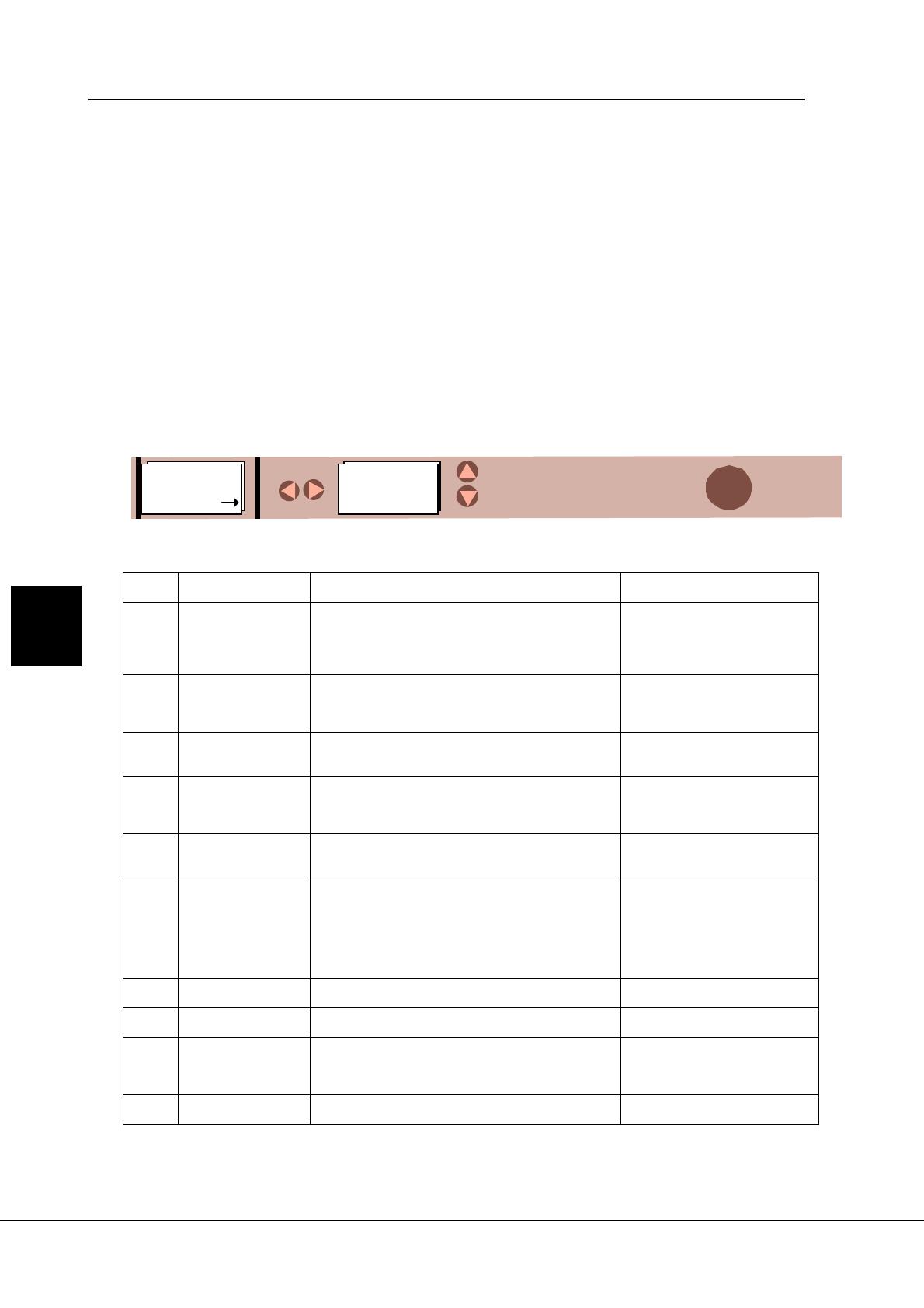
Figure 7-10. Active faults menu
Fault
codes
Fault Possible cause Checking
F1 Overcurrent The frequency converter has measured too high a
current (>4*In) in the motor output:
- sudden heavy load increase
- short circuit in the motor cables
- unsuitable motor
Check loading
Check motor size
Check cables
F2 Overvoltage The voltage of the internal DC-link of the frequency
converter has exceeded the nominal voltage by 35%
- deceleration time is too fast
- high overvoltage spikes at utility
Adjust the deceleration time
F3 Ground fault Current measurement detected that the sum of the
motor phase current is not zero
- insulation failure in the motor or the cables
Check the motor cables
F4 Inverter fault The frequency converter has detected faulty opera-
tion in the gate drivers or IGBT bridge
- interference fault
- component failure
Reset the fault and restart again.
If the fault occurs again contact
your Vacon distributor.
F5 Charging switch Charging switch open when START command active
- interference fault
- component failure
Reset the fault and restart again.
If the fault occurs again contact
your Vacon distributor.
F9 Undervoltage DC-bus voltage has gone below 65% of the nominal
voltage
- most common reason is failure of the utility supply
- internal failure of the frequency converter can also
cause an undervoltage trip
In case of temporary supply
voltage break, reset the fault and
start again.
Check utility input.
If utility supply is correct and
internal failure has occurred.
Contact your Vacon distributor.
F10 Input line supervi-
sion
Input line phase is missing Check the utility connection
F11 Output phase su-
pervision
Current measurement has detected that there is no
current in one motor phase
Check motor cables
F12 Brake chopper su-
pervision
- brake resistor not installed
- brake resistor broken
- brake chopper broken
Check brake resistor
- If resistor is OK the chopper is
broken. Contact your Vacon
distributor
F13 Drive undertem-
perature
Temperature of heat sink below -10C
7
Table 7-3. Fault codes (continues on next page)
7.7 Active faults menu
The Active faults menu can be entered from
the main menu by pushing the
Menu button
(right)
when the symbol M5 is visible on the
first line of the alpha-numeric display as
shown in Figure 7-10.
When a fault brings the frequency converter
to a stop, the fault symbol F, the ordinal
number of the fault, the fault code and a short
description of the fault are displayed. In
addition, the indication FAULT will appear
on the first line of the display. If there are
several faults at the same time, the list of
active faults can be browsed with the
Browser buttons.
The display can be cleared with the
Reset
button
and the read-out will return to the
same display it had before the fault trip.
The fault remains active until it is cleared with
the Reset button or with a reset signal from
the I/O terminal.
Note! Remove external Start signal before
resetting the fault to prevent unintended re-
start of the drive.
RESET
M5
Active faults
F 1-9
F1
1. Overcurrent
Browse active
fault list
RESET:
7_10.fh8
Vacon Page 69 (90)
Control panel
Vacon Plc Tel: +358-201-2121 Fax: +358-201-212 205
On-call: +358-40-8371 150 E-mail: [email protected]
Table 7-3. Fault codes (cont.)
7
Fault
codes
Fault Possible cause Checking
F14 Drive overtempera-
ture
Temperature of heat sink over 90C (CXS series)
Temperature of heat sink over 77C (CX/CXL series
up to 75 kW)
Temperature of heat sink over 70C (CX/CXL series
from 90 kW)
- Check the cooling air flow
- Check that the heat sink is not
dirty
- Check ambient temperature
- Check that the switching fre-
quency is not too high compared
with ambient temperature and
motor load
F15 Motor stalled The motor stall protection has tripped - Check the motor
F16 Motor overtem-
perature
The frequency converter motor temperature model
has detected motor overheat
- motor is overloaded
Decrease motor load.
Check the temperature model
parameters if the motor was not
overheated
F17 Motor underload The motor underload protection has tripped
F18 Analogue input po-
larity fault or
analogue input
hardware fault
Wrong analogue input polarity
Component failure on control board
Check the polarity of the ana-
logue input.
Contact your Vacon distributor.
F19 Option board identi-
fication
Reading of the option board has failed Check the installation
- If installation is correct, contact
your Vacon distributor
F20 10 V voltage refer-
ence
+10 V reference shorted on control board or option
board
Check the cabling from +10 V
reference voltage
F21 24 V supply +24 V supply shorted on control board or option
board
Check the cabling from +24 V
reference voltage
F22
F23
EEPROM check-
sum fault
Parameter restoring error
- interference fault
- component failure
When the fault is reset the fre-
quency drive will automatically
load parameter default settings.
Check all parameter settings
after reset.
If the fault occurs again contact
your Vacon distributor
F25 Microprocessor
watchdog
- interference fault
- component failure
Reset the fault and restart. If the
fault occurs again contact your
Vacon distributor
F26 Panel communica-
tion error
The connection between panel and the frequency
converter is not working
Check the panel cable
F29 Thermistor protec-
tion
Thermistor input of the I/O expander board has de-
tected increase of the motor temperature
- Check motor cooling and
loading
- Check thermistor connection
(If thermistor input of the I/O
expander board is not in use it
has to be short circuited)
F36 Analog input I
in
<
4mA (signal range
selected 4-20 mA)
The current in the analog input I
in
is below 4 mA
- signal source has failed
- control cable is broken
Check the current loop circuitry
F41 External fault Fault is detected in external fault digital input Check the external fault circuit or
device
Page 70 (90) Vacon
Vacon Plc Tel: +358-201-2121 Fax: +358-201-212 205
On-call: +358-40-8371 150 E-mail: [email protected]
Control panel
7.8 Active warning display
When a warning occurs, a text with a symbol
A# appears on the display. In addition, the
indication ALARM will appear in the top right
corner of the display. Warning codes are
explained in Table 7-4.
The display does not have to be cleared in
any special way.
The warning on the display does not disable
the normal functions of the push buttons.
Table 7-4. Warning codes
Code Warning Checking
A15
Motor stalled (Motor stall protection) Check motor
A16
Motor overtemperature (Motor thermal protection) Decrease motor loading
A17
Motor underload (Warning can be activated in Five
In One applications)
Check motor loading
A24
The values in the Fault History, MWh counters or op-
erating day/hour counters might have been changed
in the previous mains interruption.
No actions necessary. Take a
critical attitude to these values.
A28
The change of application has failed. Choose the application again and
push the Enter button.
A30
Unbalance current fault; the load of the segments is
not equal.
Contact your Vacon distributor.
A45
The frequency converter overtemperature warning;
Overtemperature trip limit minus 5 degrees. See Ta-
ble 7-3: F14
Check the cooling air flow and the
ambient temperature.
A46
Reference warning; the current of input I
in+
<4 mA
(Warning can be activated in Five in One applica-
tions)
Check the current loop circuitry.
A47
External warning; (Warning can be activated in Five-
InOne applications)
Check the external fault circuit or
device.
7
Vacon Page 71 (90)
Control panel
Vacon Plc Tel: +358-201-2121 Fax: +358-201-212 205
On-call: +358-40-8371 150 E-mail: [email protected]
7.9 Fault history menu
The fault history menu can be entered from
the main menu by pushing the
Menu button
(right)
when the symbol M6 is displayed on
the first line of the alpha-numeric panel.
The memory of the frequency converter can
store the maximum of 9 faults in the order of
appearance. The latest fault has the number
1, the second latest number 2 etc. If there
are 9 uncleared faults in the memory, the
next fault will erase the oldest from the
memory.
Pressing the
Enter button
for about 23
seconds resets the whole fault history. Then,
the symbol H# will change for 0.
Figure 7-11. Fault history menu
7.10 Contrast menu
In case the display is unclear you can adjust
the its contrast.
The contrast menu can be entered from the
main menu by pushing the
Menu button
(right)
when the symbol M7 is visible on the
first line of the alpha-numeric display.
Use the
Menu button (right)
to enter the edit
menu. You are in the edit menu when the
symbol C starts to blink. Then change the
contrast using the
Browser buttons
. The
changes take effect immediately.
Figure 7-12. Contrast setting
ENTER
2-3 s
Fault history reset
M6
Fault history
H 1-9
H1
2 Overcurrent
C
Contrast
15
M7
Contrast
15
7_11.fh8
7_12.fh8
7
Page 72 (90) Vacon
Vacon Plc Tel: +358-201-2121 Fax: +358-201-212 205
On-call: +358-40-8371 150 E-mail: [email protected]
Control panel
7.11 Controlling the motor from the control
panel
The CX/CXL/CXS can be controlled from either the
I/O terminals or the control panel. The active control
source can be changed with the programmable push
button b2 (see chapter 7.6). The motor can be
started, stopped and the direction of rotation can be
changed from the active control source.
7.11.1 Control source change from I/O
terminals to the control panel
After changing the control source the motor stops.
The direction of rotation remains the same as with
I/O control.
If the Start button is pushed at the same time as
the programmable push button B2, the Run state,
direction of rotation and reference value will be
copied from the I/O terminals to the control panel.
7.11.2 Control source change from the
control panel to the I/O terminals
After changing the control source, the I/O terminals
determine the run state, direction of rotation and
reference value.
If motor potentiometer is used in the application, the
panel reference value can be copied for a value of
motor potentiometer reference by pushing the start
button at the same time as the programmable push
button B2. Motor potentiometer function mode must
be "resetting at stop state" (Local/Remote
Application: param. 1. 5 =4, Multi-purpose
Application : param. 1. 5 = 9).
7
  • Page 1 1
  • Page 2 2
  • Page 3 3
  • Page 4 4
  • Page 5 5
  • Page 6 6
  • Page 7 7
  • Page 8 8
  • Page 9 9
  • Page 10 10
  • Page 11 11
  • Page 12 12

Vacon CX (Legacy Product) User guide

Type
User guide
This manual is also suitable for

Danfoss VACON CX (Legacy Product) is a frequency converter with a wide range of features that can be used to control the speed of an AC motor. It is suitable for a variety of applications, including fans, pumps, and compressors. The device is easy to use and has a detachable control panel that can be mounted remotely from the drive. It also features a variety of programmable functions that can be used to customize the drive to specific applications.

Ask a question and I''ll find the answer in the document

Finding information in a document is now easier with AI