Page is loading ...

XP5-MAN 1
DESCRIPTION
The Avtron Model XP5 SMARTSafe™ sensor is an incremental
encoder for hazardous atmosphere applications (also known as
tachometer or rotary pulse generator), allowing operation down to zero
RPM. It provides a specific number of electrical Pulses Per Revolution
(PPR) that are proportional to a shaft’s revolution. The XP5 SMARTSafe
sensor is a bearingless, couplingless, modular design, providing
unequaled reliability and mechanical performance.
An XPH encoder consists of multiple parts: a rotor and a removable
XP5 sensor module designed to be imbedded within or mounted on
OEM machines and an optional flange-mounting stator housing and
optional rotor mounting/riser shaft.
The XPH utilizes XP5 magnetoresistive sensors. This proven
technology is ideal for rugged environments since it is immune to
many contaminants that cause optical encoders to fail. All of the XP5
electronics are potted, providing full protection against liquids.
The outputs are protected against short circuits and wiring errors. An
Avtron XPH SMARTSafe encoder has a two-phase output (A,B) 90° out
of phase, with complements (A
–
, B
–
), (A Quad B Output), and a marker
pulse with complement (Z, Z
–
).
The XP5 removable sensor assembly has a diagnostic package
that includes Adaptive Electronics and a Fault-Check LED. With this
package, the SMARTSafe encoder can maintain itself, and let you
know if there is a problem before the problem causes unscheduled
downtime.
ADAPTIVE ELECTRONICS
A perfect duty cycle consists of a waveform whose “high” and “low”
conditions are of the same duration (50%/50%). It is possible over time
for the duty cycle and edge separation to change due to component
drift, temperature changes, or mechanical wear. The Adaptive
Electronics extend the life of the XP5 by constantly monitoring and
correcting duty cycle and edge separation over time.
INSTALLATION
WARNING
Installation should be performed only by qualified
personnel. Safety precautions must be taken to ensure
machinery cannot rotate and all sources of power are
removed during installation.
Refer to the following attached installation drawing XP5CRT05 for
installation information appropriate for specific hazardous locations.
NOTE
The equipment is intended for a fixed installation and
should be mounted so as to avoid electrostatic charging.
The XP5 is not considered as a safety device and is
not suitable for connection into a safety system.
It is the responsibility of the end user to ensure that the XP5 and XPH
encoder is selected correctly for the potentially explosive atmosphere
in which the equipment is to be put into service.
XP5 Sensor Part Numbers
Model Style Line Driver PPR
Connection Options
Terminal Box
Modifications
XP5- 1- w/bottom
mount bracket,
compatible with
64mm rotor
2- w/side-mount
brackets, com-
patible with
222mm rotor,
12.5” C-face
housing
8- w/side-mount
brackets, com-
patible with
143mm rotor,
8.5” C-face
housing
6- 5-24V in/out (7272)
8- Hi Power 5-24V in/
5-24V out (Hx)
A-
B-
Left Exit
M25 thread
Blanking plug
Left/Right are
as viewed
with the prod-
uct label read-
able (terminal
box at top)
Right Exit
Blanking
plug
M25 thread
Phasing
A->B CCW
A->B CCW
000- none
004- Super Magnetic Shielding
BC-50
AF-60
AK-80
AG-100
AH-120
AA-128
AM-200
AL-240
AN-256
AP-300
AE-360
AC-400
AB-480
AQ-500
AR-512
AS-600
AU-720
AV-900
AJ-960
AW-1000
AY-1024
AZ-1200
CX-1500
A3-2000
A4-2048
A5-2500
AT-3072
A7-3600
AD-4096
A8-4800
A9-5000
00-Special
Model: SMARTSafe
TM
XP5 Modular Sensor
Encoder Instructions

XP5-MAN 2
GENERAL
The sensor must be located accurately to properly center it on the
rotor and provide the correct sensor-to-rotor air gap without permitting
contact between the stationary sensor and spinning rotor. Axial shaft
float or endplay must be less than +/-0.100” inch.
Use a dial indicator gauge to ensure motor shaft runout (TIR) does not
exceed (0.004”) [0.10mm]. Apply anti-seize compound to the shaft
before mounting rotors.
CAUTION
Do not strike or pound the sensor or rotor.
Equipment needed for installation
Supplied:
XP5 Sensor
Optional:
Sensor mounting bracket
Grounding lug
Rotor riser shaft
Mounting plate
Mounting plate shims
Centering jig
Stator housing for sensors
Rotor installation hardware kit
Soc. Hd. Cap Screws
Anti-Seize Compound (copper)
Thread Locker (blue)
Air gap shim gage (plastic)
Not Supplied:
Dial Indicator
Vernier Caliper
Wrenches
CAUTION
Do not strike or pry the encoder or rotor at any time.
Damage will result and the warranty will be void.
At installation, clean and remove paint and burrs from
motor shaft and mounting face.
LOCATING SENSOR RELATIVE TO ROTOR
The sensor must be properly located to sense the rotor in both the
axial and radial directions. The rotor-sensor orientation must be
correct so that the incremental and marker tracks are correctly
sensed.
Style ‘1’- (XPH1) TDS9/10/11 Complete Mounting Assembly
MOUNTING THE BASE PLATE
1. Begin the installation process by mounting the B34975 centering
jig on the shaft using the screws provided.
2. Slide the B34972 base plate over the centering jig.
3. Insert and begin threading the base plate fastening screws into
the motor pylons. Do not tighten at this time.
4. The sensor-to-rotor axial position is adjusted by using shims
(provided) below the mounting base plate (provided). Insert (2 x
0.060) shims on each side (4 total) between the mounting base
plate and the motor mounting pylons.
5. Check the base plate to centering jig height. The centering jig
should be flush with the top of the plate. If the plate is not flush,
either add or remove shims beneath the mounting base plate. Be
sure to shim evenly on both sides of the plate. This step ensures
that the sensor will be axially aligned with the rotor when
mounted.
6. Once the base plate is at the proper height, tighten the base plate
mounting screws.
7. Remove the centering jig. The base plate is now correctly
positioned to ensure the sensor-to-rotor axial and radial position
is correct.
MOUNTING THE ROTOR
8. Mount the riser shaft on top of the machine shaft.
8A. For TDS 11SA, the riser shaft is mounted using separate (2)
1/4-20 x 1.5” screws (provided). Screws should be secured with
blue/removable threadlocker (provided). Do not use permanent
(red) threadlocker as heat to remove permanant threadlocker
cannot be applied to the rotor or riser shaft without damaging the
rotor.
9. Place the rotor on top of the riser shaft. Secure with (2) 1/4-20 x
2.75” screws (provided), use threadlocker. Add wire-loops as
required to prevent vibration-related back-out.
MOUNTING THE SENSOR
10. Slide the sensor into place, fitting the axial position bar/bracket
into the machined groove in the base plate. This properly locates
the sensor axially to the rotor. Secure the sensor using the 1/4-
20 x 1” screws, threadlocker and provided lock washers. Use
screw wire-loops as required.
11. Verify the sensor-to-rotor axial position is correct. The rotor top
should be 0.46” +/- 0.060 [11.7 +/-1.54] below the sensor
extended “snout” that protrudes toward the rotor.
11A. If the sensor-to-rotor axial position is not in the correct position,
the base plate shims can be adjusted to move the plate up or
down. Loosen the plate mounting screws to permit shim
changes. Be sure to evenly match shims on both sides. Be sure
to retighten the base plate screws
12. Using a PLASTIC shim provided (only): check the sensor-to-
rotor radial air gap; should be nominally 0.040” [1.02mm]. For
best performance and resistance to debris, the nominal gap
should be +0.005” / -0.005” [+0.127mm / - 0.127mm]. The
sensor can function properly down to 0.005” gap, but this is not
recommended as machine vibration could cause a sensor-rotor
head crash. If the sensor gap is not correct, adjust the location of
the base plate as required.
Style ‘8’ (XPH8) - 8.5” C-Face Housing with Sensor & Rotor
Refer to the XPH8 manual for rotor and stator mounting instructions.
After the rotor and sensor are installed, install the XP5 sensor into the
stator housing using the 4 screws and side mounting bars provided.
CAUTION
DO NOT use silicone sealants or caulk of any kind on
the motor or encoder face; these can cause
misalignment or sensor scraping damage. Do apply
antiseize compound (copper) to the encoder face to
assist in easy removal. The XP electronics are fully
sealed; water may enter and leave the rotor area as
needed. Remove the XPH8 bottom pipe plug in the
housing if frequent moisture buildup is expected.
WIRING INSTRUCTIONS
The XP5 terminal box is threaded for cable gland or hard conduit
interface. See XP5CRT05 for detailed requirements including torque
specification.
CAUTION
When removing or replacing the terminal box cover,
do not damage the flame path surfaces. These include
the part of the box cover that extends into the housing
and the mating surfaces on the box itself. Before
replacing the cover, be sure to inspect for scratches
or gouges: If the flame paths are scratched or gouged
this can cause an unsafe condition. Return the XP5 for
factory review.

XP5-MAN 3
To wire the XP5 sensor, first ensure there is no hazard (gas or
explosive dust) atmosphere present. Remove the (4) M5 hex head
screws from the terminal box.
The signal wiring pinout is shown on the mating terminal plug., and an
additional copy is affixed inside the wiring terminal box cover.
CAUTION
Remove the mating terminal plug before
wiring by loosening the 2 captive screws and pulling the
plug completely out of the housing. Attempting to wire
the terminal plug inside the XP5 can lead to accidental
damage of the encoder cover flame paths.
SWITCHING LEFT-RIGHT ORIENTATION ON TERMINAL BOX
The user may exchange cable entry points by removing the blanking
plug and installing it in the opposite terminal box hole. The blanking
plug must be installed per XP5CRT05.
SIGNAL WIRING
Refer to the attached wiring diagrams. Be sure to comply with all
installation requirements shown on XP5CRT05. Information on
specific connector pin-outs and phasing can be found on labels on the
encoder and in the tables included in these instructions.
The XP5 sensor can be wired for single phase or two phase,
either with or without complements, with or without markers. For
bidirectional operation, in most cases Phase A channel typically leads
phase B channel for clockwise shaft rotation as viewed from the anti-
drive or accessory end of the motor. From this position, the sensor
diagnostic LED can also be seen. See pinout and phasing tables for
exceptions.
CORRECTIVE ACTION FOR PHASE REVERSAL
1. Remove Power.
2. Exchange wires on cable, either at encoder cable
end or at speed controller end (but not both).
a) Single Ended 2 Phase Wiring (see wiring diagram)
Exchange A with B
b) Differential 2 Phase Wiring (see wiring diagram)
Exchange either A with A in the phase A pair OR B with B
in the phase B pair but NOT both.
3. Apply power and verify encoder feedback is correct.
Interconnection cable must be selected in compliance with
XP5CRT05.
Typical interconnection cable is 18-22AWG, 4 twisted pair + overall
shield. Example: Avtron B37150. Actual cables should be picked
based on specific application requirements such as abrasion,
temperature, tensile strength, solvents, etc. General electrical
requirements are: stranded copper, 20 through 16 AWG, twisted wire
pairs, braid or foil individual shields or over-all shield with drain wire.
20 AWG wire should not be used for DC power to the encoder for runs
greater than 200 feet and 22AWG should not be used for runs greater
than 100 ft. This is to minimize voltage drop between the encoder and
the controller. The smaller conductors are acceptable for the signal
lines.
WARNING
After completing the wiring procedures, reinstall the
terminal block. Proper torque is 0.5 to 0.6 Nm (4.4 to
5.3 in-lb). Do not overtighten the mating terminal
block retentions screws.
CAUTION
Before replacing terminal box cover, wipe the flame
patch surfaces clean (the part of the cover that extends
into the terminal box). Also wipe clean the mating
surface inside the terminal box. Do not use emery paper
or other abrasives to clean the flame path surfaces. Any
scratching or gouging of the surfaces can cause an
unsafe condition.
Be sure to replace the terminal box cover properly. Fully secure the
terminal box cover per XP5CRT05.
CAUTION
Terminal box cover should slide in place without
pounding or requiring heavy pull-in by the terminal
box screws. If the terminal box cover will not fit
smoothly in place, the flame paths around the cover
may have been damaged. Return the XP5 sensor unit
for factory review.
GROUNDING
The XPH encoder (and XPH sensor) do not require an intrinsic safety
ground (IS Ground). However, XP5 should be grounded in compliance
with XP5CRT05. (2) holes and (1) #10 SAE screw are provided for
convenient ground lug mounting on each side of the sensor.
MAINTENANCE
GENERAL
This section describes routine maintenance for the Avtron XP5 sensor.
For support, contact Avtron’s field service department at 216-642-
1230. For emergency after hours service contact us at 216-641-
8317. The XP5 sensor SMARTSafe circuitry includes a diagnostic
package that includes Adaptive Electronics and a Fault-Check LED.
For any maintenance operation be sure to comply with XP5CRT05.
This product has no user servicable parts. Care must be taken during
use to ensure that flameproof joints on the cover and housing are
not damaged. Repair of flameproof joints is not permissible. Contact
Nidec Industrial Solutions for dimensions of flameproof joints.
ROTOR INSPECTION
The rotor should be clean and free of magnetic debris. Ensure the
magnetic ring is intact and is not chipped at the side, or cracked.
This damage can affect encoder performance and/or result in rotor
contact with the sensor surface. Chipped or cracked rotors should be
replaced immediately.
CAUTION
Keep strong magnets away from rotor surfaces (such as
the base magnet of a dial indicator gage). Strong
magnets that contact the rotor can damage the signal
quality permanently.
Using a PLASTIC shim provided (only): check the sensor-to-rotor
radial air gap; should be nominally 0.040” [1.02mm]. For best
performance and resistance to debris, the nominal gap should be
+0.015” / -0.030” [+0.38mm / - 0.76mm]. If the sensor gap is not
correct, adjust the location of the base plate or stator housing as
required.
FAULT-CHECK
After power-up and the rotor position is checked by the sensor, the
Fault-Check LED will turn green.
If the adaptive electronics reach their adjustment limit for any
reason, the Fault-Check LED will notify the operator of an impending
failure. The LED will turn red if the Adaptive Electronics reach their
adjustment limit. This output occurs before an actual failure, allowing
steps to be taken to replace the unit before it causes unscheduled
downtime.

XP5-MAN 4
TROUBLESHOOTING
If the drive indicates a loss of encoder/tach fault and the XP5 fault-
check LED is not illuminated, check the encoder power supply. If
power is present, check polarity; one indicator of reversed power
supply is that all outputs will be high at the same time. If the drive
indicates encoder fault, but the LED shows GREEN, then check the
wiring between the drive and the encoder. If the wiring appears
correct and in good shape, test the wiring by replacing the XP5. If the
new unit shows GREEN, and the drive still shows encoder loss/tach
fault, then the wiring is faulty and should be repaired or replaced.
If the alarm output and/or LED indicate a fault (RED):
1. Check the rotor axial position relative to the sensor. See
installation drawing for rotor-to-sensor axial check measurement.
2. Check the air gap between the sensor and the rotor using a
plastic shim (do not use metal). It should be 0.040” [1.02mm]
+0.015” / -0.030” [+0.38mm / - 0.76mm].
3. Ensure the sensor is mounted at 90 degrees to the rotor.
If the alarm output and/or LED indicate a fault (RED) on a properly
mounted XP5 sensor and the rotor is properly located, replace the XP5
sensor.
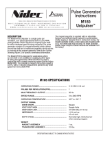
An oscilloscope can also be used to verify proper output of the XP5
sensor at the encoder connector itself and at the drive/controller
cabinet. If the outputs show large variations in the signals at steady
speed (jitter or “accordion effect”, see figure below), replace any
magnetized material nearby with non-magnetic material (aluminum,
stainless) (shafts, etc). If variations persist, consider replacing with
super-shielded models, option -004.
SENSOR REMOVAL
To remove the sensor remove the screws holding the sensor to the
mount. Take care that the sensor does not fall from the frame or flange
and crash into the rotor. Damage to the sensor or rotor could result.
ROTOR REMOVAL
Remove the rotor by hand, taking care not to damage the outer
magnetized ring.
If the rotor can not be removed by hand, use the lifter screw holes:
thread in (2) 1/4-20 screws evenly until they contact a stationary
surface. Turn each screw 1-3 more turns, and the rotor should break
free.
CAUTION
DO NOT APPLY HEAT TO THE ROTOR. DO NOT USE A GEAR
PULLER ON THE ROTOR.
VARIATION > ± 15%
PHASE A
PHASE B
Excessive Signal Jitter

XP5-MAN 5
SPECIFICATIONS
ELECTRICAL
A. Operating Power (Vin)
1. Volts .............................5-24V VIn
2. Current ......................... 400mA Max @ 5V (plus cable load)
200mA Max @ 12V (plus cable load)
100mA Max @ 24V (plus cable load)
B. Output Format (5-24V Vout)
1. 2O/ & Comp ................. A, , B, (differential line driver)
2. Marker ..........................1/Rev, Z,
C. Signal Type ......................Incremental, Square Wave, 50 ±10% Duty Cycle.
D. Direction Sensing.............See output types for phasing selection
E. Phase Sep .......................15% minimum
F. Frequency Range ............0 to 250,000 Hz
G. PPR ................................8-100000 (consult factory for higher PPRs)
H. Line Driver Specs ............See table
I. Connectors.......................Terminal box, explosion proof
J. Integral LED Indicator ...... GREEN: power on, unit ok. RED: alarm on
MECHANICAL
A. Rotor Inertia .....................
Style‘1’with64mmrotor .0.023 Oz. In. Sec
2
Style‘2’with222mmrotor 1.38-3.38Oz.In.Sec
2
Style‘8’with143mmrotor 0.12-0.46Oz.In.Sec
2
B. Acceleration .....................5000 RPM/Sec. Max.
C. Speed ..............................6000 RPM Max.
D. Weight ..............................
XP5 Sensor only .............. 4.6 lbs [2.1kg]
Style‘1’withbaseplate ....15lbs [7kg]
Style‘2’with12.5”mount 17-22 lbs [7.7 to 10kg]
Style‘8’with8.5”mount ..10-14 lbs [4.5 to 6.4kg]
E. Sensor to Rotor
Air Gap (nominal).............0.040” [1.02mm]
Tolerance .........................+0.015”/-0.030 [+0.38/-0.76mm]
F. Rotor Axial Tolerance ....... ±0.100” [±2.54mm]
ENVIRONMENTAL
Solid aluminum stator and rotor
Fully potted electronics, protected against
oil and water spray
Operating Temperature:
-50 to 85°C, 0-100% condensing humidity
See XP5CRT05 for installation notes
Certifications:
Class I Div 1, Groups C and D
Class I Zone 1, Ex db ia IIB T4 Gb
Class I Zone 1, AEx db ia IIB T4 Gb
Ex db ia IIB T4 Gb (ATEX/IECEx)
Electrical Specifications
6 8 Units
Input Voltage
5-24 5-24 VDC
Nom Output Voltage
5-24 5-24 VDC
Line Driver
7272 Hx
Output Resistance Typ
13 75 ohms
Maximum Instananeous Current
1500 3000 mA
Maximum Average Current
120 250 mA
Voh Typ
VIN-1 VIN-1
VDC
Vol Typ
0.5V 0.2 @10mA load VDC
Cable Drive Capacity
1000’ [305m] @ 5V
500’ [152m] @ 12V
200’ [60m] @ 24V
1000’ [305m]
Feet
[m]
Protection
Reverse Voltage Yes Yes
Short Circuit Yes Yes
Transient Yes Yes
Power to A, Gnd to A/ Yes Yes
Alarm
LED Green = Power On, High Signal Quality Output
LED Red = Alarm
Future
Marker
1 per revolution
Mounting Style Width
Style 1, 64mm rotor ~4 degrees
Style 2, 143mm rotor ~3 degrees
Style 8, D, 222mm rotor ~1.5 degrees
PINOUTS AND PHASING
Connector Option Phasing +V 0V A A- B B- Z Z- NC** CG*
A, B - Terminal Box CW 1 2 3 4 5 6 7 8 9 10
*Case Ground--not recommended for cable shield termination
**Future use

XP5-MAN 6
OUTLINE DIMENSIONS AND OPTION DETAILS
Mounting Style “1” - Section View as Installed. TDS 10/11
Subassembly View
XP5 SENSOR
Mounting Style “1” - Section View as Installed. TDS 10/11
Subassembly View
XP5 SENSOR
Mounting Style “1”- Assembly View, TDS 10/11
Mounting Style “1” – Rotor Axial Position
XP5 Mounting Style 1 XP5 Installed as part of XPH1 Encoder

UNLESS OTHERWISE SPECIFIED
DIMENSIONS ARE IN INCHES
THIS DOCUMENT CONTAINS
PROPRIETARY INFORMATION OF
NIDEC INDUSTRIAL SOLUTIONS
AND MAY NOT BE DISCLOSED TO
OTHERS OR USED FOR
MANUFACTURING PURPOSES
WITHOUT THE WRITTEN CONSENT
OF NIDEC INDUSTRIAL
SOLUTIONS.
DRAWN
CHECKED
APP'D
ENG
APP'D
PROD
DATE
`
8901 E. PLEASANT VALLEY ROAD
INDEPENDENCE, OH 44131-5529
IMF
PSF
REV
SIZE CAGE NO.
DWG NO.
SCALE SHEET
PATTON
XP5CRT05
0FMV7
1 OF 1
A
9/29/2017
9/29/2017
WOLFF
PATTON
XP5
3D DWG
CERTIFICATION DRAWING
USER INSTRUCTIONS
MODEL
NEXT ASSY USED ON
FINISH
PAINT PER PS
PLATE PER PS
COAT PER PS
ANODIZE PER
OTHER
TOLERANCES
0.03 0.015
1
~
NONE
REVISION
ECN NO. DESCRIPTION APPROVEDDATEREV
B
3/23/2017
DECIMALS .XX .XXX
ANGLES
``
UNLESS OTHERWISE SPECIFIED ABOVE NOTES APPLY.
Nidec Industrial Solutions
THIS DOCUMENT MUST BE PROVIDED TO THE CUSTOMER AS PART OF THE INSTRUCTION MANUAL OR AS A SEPARATE DOCUMENT.
APPROVALS:
ATEX per Certificate No. DEMKO 17 ATEX 1880X
IECEx per Certificate No. IECEx UL 17.0049X
UL/CSA 1203 per File E364384
MARKINGS:
Ex db ia IIB T4 Gb DEMKO 17 ATEX 1880X -50°C ≤ Tamb ≤ 85°C
IECEx UL 17.0049X -50°C ≤ Tamb ≤ 85°C
Telemetering Equipment for use in Hazardous Locations:
Class I, Division 1, Groups C and D
Ex db ia IIB T4 Gb
Class I Zone 1, AEx db ia IIB T4 Gb
-50°C ≤ Tamb ≤ 85°C T-Code T4
RATINGS:
MAX. VOLTAGE = 24V
MAX. CURRENT = 500 mA
MAX. SAFE AREA VOLTAGE Um = 250V
AMBIENT TEMPERATURE Tamb: -50°C ≤ Tamb ≤ 85°C
CONDITIONS FOR SAFE USE ("X" MARK):
This product has no user serviceable parts. Care must be taken during use to ensure that flameproof joints on the Cover and Housing are not damaged. Repair of
flameproof joints is not permissible. Contact Nidec Industrial Solutions for dimensions of flameproof joints.
The circuits shall be limited to overvoltage category I/II/II as defined in IEC 60664-1.
The (4) screws that secure the XP5 cover onto the XP5 enclosure require the minimum tensile strength shown below:
MATERIAL
GRADE MINIMUM TENSILE STRENGTH
A2 Stainless Steel A-70 700 Mpa (101.5 KSI)
A4 Stainless Steel A-80 800 Mpa (116.0 KSI)
Carbon Steel 8.8 800 Mpa (116.0 KSI)
Alloy Steel 12.9 1220 Mpa (176.9 KSI)
Protect the cover seal from sunlight during storage and installation.
INSTALLATION NOTES
:
Installation should only be performed by qualified personnel. Refer to WIRING INSTRUCTIONS in XP5-MAN for detailed wiring and installation instructions.
The installer
should refer to the latest edition of the following standards before installing or operating in a Hazardous Location:
EN 1127-1 Explosive Atmospheres - Explosion prevention and protection, basic concepts and methodology
EN 60079-14 Electrical apparatus for explosive gas atmospheres - Part 14: Electrical installations in hazardous areas (other than mines)
Local electric code (i.e. Article 501 of the National Electric Code (NEC) for installations in the United States)
All bolted connections must be secure. Tighten Cover Screws to 3.4 N-m (30 in-lb) max. Installer must ensure that the Rotor does not contact the Sensor or any other
stationary parts.
Encoder Housing must be grounded at one of two specified locations either on the outside or inside of housing. Use a lock washer or similar means on the external
ground location to prevent the screw from loosening. Use anti-corrosion compound on the outside ground location to prevent corrosion of the ground connection.
Ground screws must be colored green. The ground conductor size should be equal to, or larger than the power/signal conductors to the encoder.
The M25 Blanking/Close-up Plug must be assembled per manufacturer (CMP Products) installation instructions. Max. installation torque of plug is 30 N-m (22.1 ft-lb.)
For 1/2 and 3/4 NPT Blanking Plugs the customer must provide a certified plug suitable for the application.
Cable glands and conductors specified by the end user must be suitable for a service temperature of at least 94
°C
.
WARNINGS/CAUTIONS:
DO NOT OPEN IN A HAZARDOUS ENVIRONMENT WHILE ENERGIZED.
AVERTISSEMENT : Ne pas ouvrir dans un environnement dangereux, alors qu'il est sous tension.
THIS DRAWING IDENTIFIES CHARACTERISTICS REQUIRED FOR
EQUIPMENT USED IN HAZARDOUS LOCATIONS AND MAY NOT BE
CHANGED WITHOUT THIRD PARTY APPROVAL. THIRD PARTIES MUST
BE IDENTIFIED FROM IDENTIFICATION LABELS
.
EA1328 A
ADD NOTE: "FOR 1/2 AND 3/4 NPT BLANKING
PLUGS..."
10/10/17
PATTON
WOLFF

XP5-MAN 8
REV: 000
REV DATE: 11/27/17
SMARTSafe is a trademark of Nidec.
Features and specifications subject to change without notice.
Nidec standard warranty applies. All dimensions are in inches [mm].
OUTLINE DIMENSIONS AND OPTION DETAILS
These instructions have been reviewed and the product evaluated as suitable for our application.
Company Name
Authorized Company Representative
Title Date
8901 E. PLEASANT VALLEY ROAD
•
INDEPENDENCE, OHIO 44131-5508
TELEPHONE: (1) 216-642-1230
•
FAX: (1) 216-642-6037
E-MAIL: [email protected]
•
WEB: www.avtronencoders.com
All Dimensions showing inches [mm]
XP5 Installed as part of XPH1 Encoder
/