Page is loading ...

Quick Guide Flex Gateway G2
Revision 012219

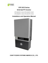
Interface & Indicators
Ethernet Port
WiFi Module Port
Terminating Res Switch
Pass-through Port
Reboot Button
Switch Signal
No-LCD INV Port
Terminating Res Switch
RS485 & DC in 9~24V
Internal Installation
(Refer to Pages 3-8)
Activity
Cloud
RS485
Power
External Installation
(Refer to Page 9-12)
RS485 & DC in 9~24V
A
B
A+ B- G
Vin GND A+ B- G
Page 1

Page 2
Switch
Activity
Cloud
RS485
Power
Default
1
ON
1
ON
Notice:
If the length of the cable connecting to the RS485 port or the Pass-through port
of
the Flex Gateway is over 1000 meters, the Terminating Resistor Switch must
be set to the ON position. Doing so will reduce signal reflection on the line.
Activity
Fast Blink: Execute Command
Blink: Gateway Heartbeat
Cloud
ON: Success Connected
Fast Blink: Shake Hands with Cloud
Blink: LAN Activity
OFF: Disconnected
RS485
Blink: Device R/W
OFF: No Activity
Power
ON
OFF
Contents Model Note
Flex Gateway G2 FG4E-US DC 9~24V
WiFi Module CPLK-US
Accessories D2XH Cable, 3 Standoffs with Screws,
3-Pin Connector, 5-Pin Connector
FG4E Enclosure 80mm * 92.5mm * 35mm
Scope of Delivery
Terminating Resistance
Switch

Page 3
Ethernet
RS485
Data logger
Ethernet
Cellular
Fiber
Meter
RS485
Weather Station
Ethernet
RS485
Modbus/TCP Converter
AC/DC
Power
- +
Inverter
ID:101
Inverter
ID:102
Inverter
ID:117
Switch
RS485
Surge
S
S
- +
- +
Example #1
Communication Box
Install the Flex Gateway in the first inverter of the
RS485 Daisy Chain.
An Ethernet cable/connection from the Comm-Box to
the inverter/Flex Gateway is required (not supplied)
A
Installation Option
Internal in Wire-Box of the Inverter
Communication Box typically
includes
these devices

Page 4
Ethernet
RS485
Data logger
Ethernet
Cellular
Inverter
ID:101
Inverter
ID:102
Inverter
ID:117
Switch
RS485
Surge
S
S
- +
- +
Example #2
Communication Box
RS485
Meter
RS485
Weather Station
Install the Flex Gateway in
the first inverter of the RS485
Daisy Chain.
An Ethernet cable/connection
from the Comm-Box to the
inverter/Flex Gateway is
required (not supplied).
AC/DC
Power
- +
Communication Box typically
includes
these devices

Page 5
The Communication Board within the Inverter Wire-Box
RS485 Port
1
Inverter Wire-Box
1. Remove the (3) screws that attach
the inverter Communication B
oard in
the Wire-Box using a #2 Phillips bit.
2
2. Replace the screws with the
(3) standoffs included in the
Flex Gateway Kit.
6-PIN Header
6-PIN Connector
3
3. Install the Flex Gateway by
carefully aligning the 6-PIN header in
the upper left-hand corner of the
Communication Board.
Install the (3) screws into the stand-offs
to secure the Flex Gateway in place.
Install the 3 screws and torque to 7 in-
lbs using a #2 Phillips bit.

Page 6
RS485 of 3rd Party Data Logger
RS485 Inverter Daisy Chain
Ethernet Port
4
4. Connect the 3rd Party Datalogger to the Pass-Through in the bottom left-hand corner
of the Flex Gateway using the 3-Pin Connector provided in the Flex Gateway Kit.
NOTE: Half duplex or "2-wire" RS-485 cabling must include a signal ground (or zero volt)
reference for reliable operation.
5. Connect the RS485 inverter Daisy Chain to the inverter Communication Board
using the 5-Pin Connector provided in the Flex Gateway Kit.
NOTE: The 5-Pin Connector is installed at the port on the bottom of the inverter
Communication Board (behind the Flex Gateway).
NOTE: Half duplex or "2-wire" RS-485 cabling must include a signal ground (or zero
volt) reference for reliable operation.
6. The RJ45 LAN cable is inserted into
the Ethernet port of the Flex Gateway.
The LAN cable must be able to access
the Internet without port filtering behind
the firewall.
A+ B- G
Vin GND A+ B- G
Signal Gnd
Signal Gnd
A + / B - / G
A + / B - / G
55
6

Page 7
RS485 Daisy Chain
Pass-through
D2XH Cable (Provided)
WiFi Module
Ethernet PortWiFi
Inverter
3rd Party
Data
Logger
RS485 A+ / B- / G
7
7. WiFi module is connected to the WiFi port of
the Flex Gateway via the D2XH cable.
Scan the QR-code to complete the CPS Connect
app download and installation by using mobile
phones that can access the Internet.
Internet
RS485 A+ / B- / G

Page 8
Inverter Wire-Box
Pass-through
Ethernet Port
3rd Party
Data
Logger
PAD 1
Inverter101
PAD 2
Inverter1
Inverter
RS485 A+ / B- / G
Inverter117 Inverter17
The Flex Gateway may be installed in the middle of the inverter Daisy Chain.
Or, alternatively the Flex Gateway may be used to combine two separate
inverter Daisy Chains into one. NOTE: Modbus IDs may not be duplicated.
When the inverters are monitored via the Flex Gateway, a unique Modbus ID, also
referred to as an RS-485 address, for each inverter can be set up through the LCD
interface.
Up to 70 inverters can be connected together in the communication network.
RS485 A+ / B- / G

Page 9
1
1. The Flex Gateway may be installed in the FG4E Enclosure as
shown. The Flex Gateway Enclosure includes a DIN rail mounting
clip for installation in an external NEMA4 communication box.
Screw M3*8
Screw M3*6
Installation Option
B
External
In Communication Box

Page 10
Ethernet
RS485
Data logger
Ethernet
Cellular
Fiber
Meter
RS485
Weather Station
Ethernet
RS485
Modbus/TCP Converter
AC/DC
Power
- +
Inverter
ID:101
Inverter
ID:102
Inverter
ID:117
Switch
Example #1
Communication Box
RS485
Surge
S
S
- +
- +
Pass-through
Ethernet
RS485
2 Typical
NOTE: Don’t use Modbus ID
160. This address is reserved
for the Broadcast Command.
16AWG Ground Wire (not supplied)
Inverter
RS485 A+ / B- / G
Vin / Gnd
RS485
A+ / B- / G

Page 11
Ethernet
RS485
Data logger
Ethernet
Cellular
AC/DC
Power
- +
Inverter
ID:1
Inverter
ID:2
Inverter
ID:17
Switch
Example #2
Communication Box
Pass-through
Ethernet
RS485
Inverter
ID:101
Inverter
ID:102
Inverter
ID:117
RS485
Surge
S
S
- +
- +
16AWG Ground Wire (not supplied)
NOTE: Don’t use Modbus ID
160. This address is reserved
for the Broadcast Command.
Inverter
RS485 A+ / B- / G
Vin / G nd
RS485
A+ / B- / G

Ethernet
RS485
Data logger
Ethernet
CellularSwitch
Example #3
Communication Box
RS485
Meter
Inverter
ID:101
Inverter
ID:102
Inverter
ID:117
RS485
Weather Station
AC/DC
Power
- +
Page 12
Pass-through
Ethernet
RS485
4
RS485
Surge
S
S
- +
- +
With Meter &
Weather Station
NOTE: The Modbus ID of the
Meter and Weather Station should
not be included in the Modbus
range of the Flex Gateway.
16AWG Ground Wire (not supplied)
Inverter
RS485 A+ / B- / G
Vin / Gnd
RS485
A+ / B- / G

Open the firewall ports before commissioning !
If a firewall is used to protect the network, the following port must be opened
both ways (incoming and outgoing communications):
TCP 1883 with destination IP 47.254.52.209
If the Flex Gateway firmware version is lower than 1.6000, the following port
must be opened both ways:
TCP 80 and 88 with destination IP 47.254.31.163
If the user or site owner is unable to have those ports opened, he/she will not
be able to get the full benefit of the remote diagnostics and firmware updates.
It is recommended to use a separate modem/router so that the inverters’
network is not part of the high security network used on the site.
Page 13

Page 14
Setup and Activation
1 2
WiFi Gateway
Flex Gateway
No-LCD Inverter
Firmware
Installer
CPS Service
Open the CPS Connect app and click
“Flex Gateway” under the “Installer” tab.
Ensure the D2XH Cable and WiFi Module
are connected to the Flex Gateway card.
Select WiFi settings and connect to the
network name beginning with “CPLK-“.
The password is “Password”, and is
case sensitive.
WiFi Setting
Next
Connect to ModuleBack
Connected to the WiFi SSID
start with “CPLK-”
And the password is
“Password”
WiFi
Module

Page 15
3 4
Quit New Gateway Activate
Once connected to the network, navigate
back to the CPS Connect app. NOTE: Do
not close the app as you will need to
repeat the previ-ous steps.
“DHCP” enabled means that the card will
try to obtain the IP and DNS by itself
from your server.
These are the recommended settings. If
your network administrator requires a
static IP, disable this feature and enter it
manually.
“Inverter Baud Rate” :
Speed 2400 / 4800 / 9600 / 14400 / 19200
Parity E / N / O
Data 8 / 9
Stop 1 / 2
“Modbus Range” can be select in the
range of 1 - 246.
Upload Interval (Minutes): You
may select
the upload interval for the data going to
the cloud.
DHCP
Inverter Baud Rate
Modbus Range 1 ~ 16
9600 N81
Test Save the Config
Basic Ethernet RS485
Flex Gateway Name: unknown
Model: FG4E-US
SN: 1088000000106
Hardware Ver: V1.4.1751
Firmware Ver: V01.6142
Quit New Gateway Activate
DHCP
Upload Interval
Advanced Settings
1 Minutes
Test Save the Config
Basic Ethernet RS485
Runtime: 22 Minutes
MQTT Connection: DISCONNECT
MQTT Server Host: None
Routing: LINK_OFF
MAC: 00005E113C08
IP Address: 0.0.0.0
Mask: 0.0.0.0
Gateway: 0.0.0.0
DNS: 0.0.0.0

Page 16
5
Quit New Gateway Activate
If it is showing 0.0.0.0
Please contact your network administrator
for further help.
If the card has successfully obtained an IP
address it will be displayed as shown.
Quit New Gateway Activate
DHCP
Upload Interval
Advanced Settings
1 Minutes
Test Save the Config
Basic Ethernet RS485
Runtime: 25 Minutes
MQTT Connection: CONNECT
MQTT Server Host: cps.j1st.io 1883
Routing: LINK_ON
MAC: 00005E113C08
IP Address: 192.168.1.100
Mask: 255.255.255.0
Gateway: 192.168.1.1
DNS: 6.6.6.6
DHCP
Upload Interval
Advanced Settings
1 Minutes
Test Save the Config
Basic Ethernet RS485
Runtime: 22 Minutes
MQTT Connection: DISCONNECT
MQTT Server Host: None
Routing: LINK_OFF
MAC: 00005E113C08
IP Address: 0.0.0.0
Mask: 0.0.0.0
Gateway: 0.0.0.0
DNS: 0.0.0.0

Page 17
6 7
Back Advanced Settings
When ”Reboot” is selected, this will only
restart the Flex Gateway. It will not erase
any settings.
When “Reset” is selected, this will restore
the Flex Gateway to the factory settings.
All previous data will be permanently
deleted.
In the “Ethernet” settings, the user can
connect the Flex Gateway to the two
different servers.
Inverter Port
Pass-through Port
Ethernet
Reboot
Reset
Upgrade Firmware
Back Ethernet Execute
DHCP
Protocol of Server
MQTT
SunSpec

Page 18
8 9
Quit New Gateway Activate
Click “Test” to check the default
configuration. The Flex Gateway will
query each inverter in the Daisy Chain
and display the connection with all units.
Make sure all inverters have a unique
Modbus ID address.
Once the “Test” has completed, the user
should be able to see all the inverters
that were found within the given range.
If the user is missing an inverter, make
sure it has a unique Modbus ID and is
within the range. Once all the expected
inverters are found, press “Save the
Config”.
At this point the “Activate” button at the
top right corner should be highlighted.
DHCP
Inverter Baud Rate
Modbus Range 1 ~ 32
9600 N81
Test Save the Config
Basic Ethernet RS485
---------------------------------------
Test:
1. Server Connection [ OK ]
2. Query Inverter 1...
Quit New Gateway Activate
DHCP
Upload Interval
Advanced Settings
1 Minutes
Test Save the Config
Basic Ethernet RS485
Runtime: 25 Minutes
MQTT Connection: CONNECT
MQTT Server Host: cps.j1st.io 1883
Routing: LINK_ON
MAC: 00005E113C08
IP Address: 192.168.1.100
Mask: 255.255.255.0
Gateway: 192.168.1.1
DNS: 6.6.6.6

Page 19
10 11
Press “Activate”. The app will prompt you
for an internet connection.
This will require the user to disable the
WiFi connection between his/hers smart
device (mobile phone/tablet) and the WiFi
module, and enable the 3G/4G network
of the smart device to take over.
Once you disable the WiFi, navigate back
to the app. Do not close the app.
Ensure the mobile phone is connected to
the Internet during this step.
Input the email address
"[email protected]" and click “Next”.
If you are not sure about the email.
Please contact our service team.
Quit
Next
Email of Site Owner
/