Page is loading ...

Installation and user manual
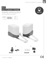
( WORM )
for swing gates
24V Encoding
system
intensive1A
AUTOMATION KIT
EN
Comfort
kit
Motors
Control unit
2 remote control
Blinker
Motors
Control unit
2 remote control
Blinker
Photocells
Safety
kit

1.1 GENERAL PRECAUTION:
1
INDEX
WARNING :
This user manual is only for qualified technicians who is specialized in installations and automations.
(1) All installations, electrical connections, adjustments and testing must be performed only after
reading and understanding of all instructions carefully.
(2) Before carrying out any installation or maintenance operation, disconnect the electrical power
supply by turning off the magneto thermic switch connected upstream and apply the hazard area
notice required by applicable regulations
(3) Make sure the existing structure is up to standard in terms of strength and stability
(4) When necessary, connect the motorized gate to reliable earth system during electricity connection phase.
(5) Installation requires qualified personnel with mechanical and electrical skills.
(6) Keep the automatic controls (remote, push bottom, key selectors…etc) being placed properly
and away from children.
(7) For replace or repair of the motorized system, only original parts must be applied. Any damage
caused by inadequate parts and methods will not be claimed to motor manufacturer.
(8) Never operate the drive if you have any suspect with what it might be faulty or damage to the system.
(9) The motors are exclusively designed for the gate opening and closing application, any other
usage is deemed inappropriate. The manufacture should not be liable for any damage resulting
from the improper use. Improper usage should void all warranty, and the user accepts sole
responsibility for any risks thereby may accrue.
(10) The system may only be operated in proper working order. Always follow the standard procedures
by following the instructions in this installation and operating manual.
(11) Only command the remote when you have a full view of the gate.
Please keep this installation manual for future reference.
1.1 General Safety Precaution
1.2 Installation
A. Standard Installation
B. Dimension Chart
C. Motor Fixing
D. Wire Connection
E. Emergency Release
1.3 Technical Features
1.4 Maintenance
P.1
P.2
P.2
P.2
P.3
P.3
P.4
P.4
P.5
Low Voltage
24V
24V power supply
for great safety
Durability
Solid material apply
with lasting usage
EZ Instal
Easy installation
and user friendly
interface
Silence
Worm gear application
give silence operation
Manual release device
with easy use and
highly protection
Key Release

ASTANDARD INSTALLATION
BDIMENSION CHART
1. 24V DC blinker with antenna
2. Push Button
3. Control Box
4. Photo Sensor
5. 24V DC gate opener
6. Transmitter
2
1.2 STANDARD INSTALLATION
Comply with the measures shown on the chart for proper installation. Adjust the gate structure
to fit it for best automation, if necessary.
Before preceding the installation, be sure that gate moves freely and that:
1) Hinges are properly positioned and greased.
2) No obstacles in the moving area.
3) No frictions between two gate leafs or with the ground while moving
RX - 0.5m
1.5 m
1.5 m
0.5 m
0.5 m
1.5 m
4
6
23
1
4
5 5

CMOTOR FIXING
Assemble the rear bracket and fix it on the pillar.
DWIRE CONNECTION:
3
Remove the wire cover and fix the rear bracket with the pin. Release the gate opener and place
the pin into the fitting position no.1 and no. 2
Make sure the gate openers are mounted in horizontal position especially in those positions.
1) Gate in “CLOSE” position
2) Gate in “OPEN” position
3) Gate at “45。angle” position
Prior to weld the bracket on the gate leaf(if necessary), cover the gate opener to prevent
damages from sparks.
5
4
3
2
1
TO CONNECT MASTIFF WITH CONTROL UNIT
White
Yellow
Red
Green
Black
Motor (+)
Motor (-)
Hall Sensor (5V)
Hall Sensor (Signal)
Hall Sensor (GND)
1
2
3
4
5
With Hall Sensor
Motor (+)
Motor (-)
-
-
-
Standard Motor
no.1
no.2
A
B

EEMERGENCY RELEASE
4
Step 2Step 1 Step 3
In case of power failure, push the lid of release chamber and move forward. Insert the key and
turn clockwise to unlock, then turn around the knob to release. To restore the automation, simply
reverse the above procedures.
Step1. Push the lid of release chamber and move forward
Step2. Insert the key and turn clockwise to the unlock position
Step3. then turn clockwise the knob to release the motor.
Make sure the White bar on the knob is on the position
opposite to the triangle indication.
To restore the automation, simply reverse the above procedure.
1.3 TECHNICAL FEATURES :
Motor
Type
Max Absorbed Power
Peak Thrust
Nominal Thrust
Stroke Length
Power Supply
Nominal Input Power
Maximum Operating Current
Maximum Gate Weight
Maximum Gate Length
Duty Cycle
Operating Temperature
Dimension
Weight
24Vdc motor with mechanical release
Worm gear
144W
3000N
3000N
300mm
24Vdc
2A
5.5A for maximum 10 seconds.
300 kg per leaf
3 meters
20%
-20℃~+50℃
837mm x 123mm x 124mm
6.6kg
123
328
124
61.5
61.5
min837~max1197

5
1.4 Maintenance:
Conduct the following operations at least every 6 months. If in high intensity of use,
shorten the period in between.
Disconnect the power supply:
(1) Clean and lubricate the screws, the pins, and the hinge with grease.
(2) Check the fastening points are properly tightened.
(3) Make the wire connection are in good condition.
Connect the power supply:
(1) Check the power adjustments.
(2) Check the function of the manual release.
(3) Check the function of photocells or other safety devise.
Hotline (Fr)
From monday to friday : 9
h
>12
h
- 14
h
>18
h
00 33 (0)2 51 61 01 21
0 810 90 24 21
(coût d’un appel local)

PURCHASE LOCATION
company : .................................................................... date of purchase : .....................................
city : .............................................................................. zip code : .................................................
YOU
company : ................................................................................... .......................................................
name : ........................................................... surname : ................................................................
phone : .................................................. email : .............................................................................
city : .............................................................................. zip code : .................................................
!
YOUR PRODUCT
product name : automation kit for swing gates INTENSIVE4
gencod (13 numbers) : ......................................................................................................................
batch number (close to gencod location) : ..................................................................................
WARRANTY 3 YEARS
WARRANTY DECLARATION
TO RETURN BY MAIL TO :
your installer or distributor
To be send at least 1 month after purchasing. Please keep your proof of purchase.

Index
1. BOÎTIER DE CONTRÔLE
2. INSTALLATION
2.1 SW1 MODES DE FONCTIONNEMENT
2.1.1 MODE RALENTISSEMENT (Dip 1.S/F Set)
2.1.2 SURINTENSITÉ (Dip 2.Over2 & Dip 3.Over1)
2.1.3 MODE FERMETURE AUTOMATIQUE (Dip 4.Auto 3, Dip 5.Auto 2 & Dip 6.Auto 1)
2.1.4 PHOTOCELLULES (Dip 7.Photo)
2.1.5 FEU CLIGNOTANT AVEC ANTENNE INTÉGRÉE (Dip 8.Light)
2.2 SW2 MODES DE FONCTIONNEMENT
2.2.1 GÂCHE ÉLECTRIQUE (Dip 5.Latch)
2.2.2 RÉGLAGE DU MOTEUR- RALENTISSEMENT (Dip 6.Slow)
2.2.3 RÉGLAGE DU MOTEUR- VITESSE (Dip 7.Fast)
2.2.4 FONCTIONNEMENT DU PORTAIL SIMPLE ET DOUBLE (Dip 8.Ds/Set)
2.3 INDICATION DE LED
2.4 MÉMORISATION ET L'EFFACEMENT DE TÉLÉCOMMANDE
2.5 PROCESSUS D'APPRENTISSAGE DU SYSTÈME
2.6 FONCTIONNEMENT/ACTIVATION DU PORTAIL
2.7 LOGIQUE DE MOUVEMENT
2.8 L'UTILISATION AVANCÉE DE TÉLÉCOMMANDE
3. MAINTENANCE ET DIAGNOSTIC DE PANNES
1
3
3
3
3
3
4
4
4
4
4
4
4
4
5
5
5
5
6
6
Assistance
téléphonique
(Fr)
Du lundi au vendredi : 9h>12h - 14h>18h
Tél. 02 51 61 01 21
0 810 90 24 21
(coût d’un appel local)

3
2.1 SW1 MODES DE FONCTIONNEMENT
2.1.1 Mode de ralentissement (Dip 1)
2.1.2 Réglage de puissance (Dip 2.Over2 & Dip 3.Over1)
Dip Switch 3 OFF
Dip Switch 3 ON
Dip Switch 3 OFF
Dip Switch 3 ON
Dip Switch 2 OFF
Dip Switch 2 OFF
Dip Switch 2 ON
Dip Switch 2 ON
2A
3A
4A
5A
OVER1 OVER2 Intensité (Amp)
2). INSTALLATION
NC: Non utilisé
ON: Le moteur ne démarre pas doucement et ne ralentit pas en fin de course.
OFF: Le moteur démarre doucement et ralentit en fin de course.
2.1.3 Mode fermeture automatique (Dip 4.Auto 3, Dip 5.Auto 2 & Dip 6.Auto 1)
Dip switch 6 OFF
Dip switch 6 ON
Dip switch 6 OFF
Dip switch 6 ON
Dip switch 6 OFF
Dip switch 6 ON
Dip switch 6 OFF
Dip switch 6 ON
Dip Switch 5 OFF
Dip Switch 5 OFF
Dip Switch 5 ON
Dip Switch 5 ON
Dip Switch 5 OFF
Dip Switch 5 OFF
Dip Switch 5 ON
Dip Switch 5 ON
Dip Switch 4 OFF
Dip Switch 4 OFF
Dip Switch 4 OFF
Dip Switch 4 OFF
Dip Switch 4 ON
Dip Switch 4 ON
Dip Switch 4 ON
Dip Switch 4 ON
Pas de fermeture automatique
3 sec.
10 sec.
20 sec.
40 sec.
60 sec.
120 sec.
300 sec.
Auto-ferme 1 Auto-ferme 2 Auto-ferme 3 Effect
En mode fermeture automatique, quand votre portail est complètement ouvert, le fait d’appuyer sur la télécommande
ou le sélecteur à clé fait que votre portail se refermera immédiatement (en oubliant le temps de pause programmé).
Transformer
24V
24V
24V
Avant d’alimenter la carte électronique,
veuillez régler vos clips switch en fonction
du mode de fonctionnement désiré.
Paragraphe 2.1 jusqu’à paragraphe 2.4.

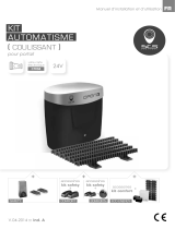
Installation and user manual
24V
intensive
CONTROL BOX
EN
©

Index
1. Control Box
2. Setting
2.1 SW1 Dip Switch Setting
2.1.1 Slowdown Adjustment (Dip 1.S/F Set)
2.1.2 Over-current Adjustment (Dip 2.Over2 & Dip 3.Over1)
2.1.3 Gate Auto-close Adjustment (Dip 4.Auto 3, Dip 5.Auto 2 & Dip 6.Auto 1)
2.1.4 Photocells Adjustment (Dip 7.Photo)
2.1.5 Flashing Light Adjustment (Dip 8.Light)
2.2 SW2 Dip Switch Setting
2.2.1 Electric Latch Adjustment (Dip 5.Latch)
2.2.2 Slowdown Speed Adjustment of The Gear Motors (Dip 6.Slow)
2.2.3 Operation Speed Adjustment of The Gear Motors (Dip 7.Fast)
2.2.4 Single and Dual Gate Operation Adjustment (Dip 8.Ds/Set)
2.3 LED Indication
2.4 Transmitter Memorizing and Erasing Process
2.5 System Learning Process
2.6 Gate Operation
2.7 Gate-moving Logic
2.8 Advanced Operation of the Transmitter
3. Trouble Shooting
1
3
3
3
3
3
4
4
4
4
4
4
4
4
5
5
5
5
6
6
Hotline
(Fr)
From monday to friday : 9h>12h - 14h>18h
02 51 61 01 21
0 810 90 24 21
(coût d’un appel local)

1
CONTROL BOX INSTALLATION
1). Control Box
1. Decide the installation position of control box first, it is suggested to be installed near the gate and should
be protected from possible damage. Be aware of the motor cable length before deciding the installation position.
2. Remove the cover by unscrewing the four screws on the cover. See Figure 1(1).
3. Use a screwdriver to puncture the holes beneath the bottom of the control box. See Figure 1(2).
4. Secure it on the wall. See Figure 1(3).
Figure 1(1) Figure 1(2) Figure 1(3)
5. Wiring Connection:
Prepare all the wires of the accessories beforehand and connect the wires to the gear motors and accessories on
the PCB as shown in Figure 1(4). All of the wiring connections of the accessories are not requested to
distinguish the positive (+) and the negative (-) polarity.
1). PF-1 Flashing light: Connect the two wires from the flashing light to the terminal LIT (+) and LIT (-) on the PCB.
2). PEL-1 Electric Latch: Connect the two wires from the electric latch to the terminal LAT (+) and LAT (-) on the PCB.
3). Gate openers: Refer to Figure 1(4) and connect the wires separately to the terminals on the PCB.
M1: Connect the motor wire (White +) to the terminals M1 (+), and (Yellow -) to the M1 (-).
Connect the hall sensor wires red, green, and black to the terminals 5V, S1, and GND.
M2: Connect the motor wire (White +) to the terminals M2 (+), and (Yellow -) to the M2 (-).
Connect the hall sensor wires red, green, and black to the terminals 5V, S2, and GND.
Notes:
For gates opened outward,
M1: Connect the motor wire (Yellow -) to the terminals M1 (+), and (White +) to the terminals M1 (-).
M2: Connect the motor wire (Yellow -) to the terminals M2 (+), and (White +) to the terminals M2 (-).
4). PH-1 Photocells: See Figure 1(4)
(A). In the installation of one set: Connect the wires referred to 7 and 9.
And remove the electric jumper “JP1”.
(B). In the installation of two sets: connect the wires referred to 7, 8, 9 and 10.
And remove both the electric jumper “JP2”and”JP1”. Figure 1(4)
24V
GND
DKEY
SKEY
GND
GND
Phot2
Phot1
24V
24V
! CAUTION: There is control board inside, punch with care, do not damage the board

2
Transformer
Figure 1(4)
M1
Key Selector
TX1 TX2 RX1 RX2
Push Button
Latch M2
230V≈
24V
24V
24V

3
2.1 SW1 Dip Switch Setting
2.1.1 Slowdown Adjustment (Dip 1.S/F Set)
2.1.2 Over-current Adjustment (Dip 2.Over2 & Dip 3.Over1)
Dip Switch 3 OFF
Dip Switch 3 ON
Dip Switch 3 OFF
Dip Switch 3 ON
Dip Switch 2 OFF
Dip Switch 2 OFF
Dip Switch 2 ON
Dip Switch 2 ON
2A
3A
4A
5A
OVER1 OVER2 Current (Amp)
2). SETTING
Before powering on the control unit, the
following dip switch setting must be
decided by gate weight and installation
environment first. See Figure 2
NC: No Connection
ON: The gear motors do not slow down before the gates completely close or open.
OFF: The gear motors slow down before the gates completely close or open.
2.1.3 Gate Auto-close Adjustment (Dip 4.Auto 3, Dip 5.Auto 2 & Dip 6.Auto 1)
Dip switch 6 OFF
Dip switch 6 ON
Dip switch 6 OFF
Dip switch 6 ON
Dip switch 6 OFF
Dip switch 6 ON
Dip switch 6 OFF
Dip switch 6 ON
Dip Switch 5 OFF
Dip Switch 5 OFF
Dip Switch 5 ON
Dip Switch 5 ON
Dip Switch 5 OFF
Dip Switch 5 OFF
Dip Switch 5 ON
Dip Switch 5 ON
Dip Switch 4 OFF
Dip Switch 4 OFF
Dip Switch 4 OFF
Dip Switch 4 OFF
Dip Switch 4 ON
Dip Switch 4 ON
Dip Switch 4 ON
Dip Switch 4 ON
No auto-close
3 sec.
10 sec.
20 sec.
40 sec.
60 sec.
120 sec.
300 sec.
Auto-close 1 Auto-close 2 Auto-close 3 Effect
Note: Auto-close mode activates when the gates move to the end position or stopped manually. If the transmitter,
push button, or the key selector is activated before the auto-close counting, the gate will close immediately.
Transformer
24V
24V
24V

4
2.1.4 Photocells Adjustment (Dip 7.Photo)
ON: When encountering any obstacles, the gates will stop during opening phase ; stop and reverse during closing phase.
OFF: The gate will keep moving when encountering any obstacles during closing and opening phases.
2.1.5 Flashing Light Adjustment (Dip 8.Light)
ON: The flashing light blinks for 3 seconds before the gate moves, and blinks simultaneously during the movement.
OFF: The flashing light blinks and the gate moves simultaneously.
2.2.1 Electric Latch Adjustment (Dip 5.Latch)
2.2 SW2 Dip Switch Setting
ON: The electric latch functions when dip switch is set to “ON”.
OFF: The electric latch does not function when dip switch is set to “OFF”.
2.2.2 Slowdown Speed Adjustment of The Gear Motors (Dip 6.Slow)
ON: The speed is 70% output of the full speed.
OFF: The speed is 50% output of the full speed.
2.2.3 Operation Speed Adjustment of The Gear Motors (Dip 7.Fast)
ON: The speed is 100% output of the full speed.
OFF: The speed is 80% output of the full speed.
2.2.4 Single and Dual Gate Operation Adjustment (Dip 8.Ds/Set)
ON: Dual Gates operation in system learning and normal operation.
OFF: Single Gate operation in system learning and normal operation.
2.3 LED Indication
LED1 System Learning: LED1 blinks once when single-gate learning is completed ;
LED1 blinks twice when dual-gate learning is completed.
LED2 RF : If the switch of the transmitter, key selector, or the push button is activated, LED2 will be on.
LED3 Photocells 1 : LED3 will be on when the first pair of the photocells are activated.
LED4 Photocells 2 : LED4 will be on when the second pair of the photocells are activated.
LED5 RF Indicator : LED5 will be on when RF signal is received.
Transformer
LED1
SYSlearn
LED2
RFLED
LED3
LED4
Ph01
LED5
Ph02
RFlearn
24V
24V
24V

5
2.5 System Learning Process
Step1: Connect the master motor wires to M1 terminals and the slave motor wires to M2 terminals correctly. If only
one gate is installed, the motor wires have to be connected to M1 terminals.
Step2: Press and hold the S2 button on the PCB for 5 seconds. After LED1 blinks once per second, press the
button on the transmitter to choose dual-gate(A button) or single-gate(B button) system learning.
In system learning mode, the gates will proceed with the following procedures.
(A) Dual-Gate Mode: Slave Gate closes→Master Gate closes→Master Gate opens→Slave Gate opens→Slave
Gate closes→Master Gate closes.
(B) Single-Gate Mode: Master Gate closes→Master Gate opens→Master Gate closes.
The completion of system learning:
(A) For Dual-Gate installation: The system learning is completed when LED1 quickly blinks twice per second.
(B) For Single-Gate installation: The system learning is completed when LED1 quickly blinks once per second.
Notes:
(A) System learning fails and needs to be learned again when an unpredictable interruption occurs.
(B) Once the system learning is completed, there is no need to proceed with the learning process again when
there isa power failure.
(C) The slave gate opens 3 seconds after the master gate opens and the master gate closes 3 seconds after the
slave gate closes.
2.6 Gate Operation
Press the button “A” on the transmitter for dual-gate operation.
Press the button “B” on the transmitter for single-gate
operation in either single-gate or dual-gate installation.
2.7 Gate-moving Logic
(A) In gate-opening phase: The gates stop if the transmitter/push button/key selector is activated, and close when
the transmitter/push button/key selector is reactivated.
(B) In gate-closing phase: The gates stop if the transmitter/push button/key selector is activated, and open when
the transmitter/push button/key selector is reactivated.
(C) In gate-opening or gate-closing phase: For safety purpose, the gates stop if encountering obstacles.
2.4 Transmitter Memorizing and Erasing Process
(A) Transmitter Memorizing: Press and hold the S3 button on the PCB for 1 second and then the blue LED
indicator on the RF board will be “ON”. Press A button for dual-gate installation ; press B button for
single-gate installation on the transmitter within 5 seconds. The transmitter learning is completed
when the blue indicator is “OFF”.
(B) Transmitter Memory Erasing: Press and hold the S3 button on the PCB for three seconds.
(C) One radio receiver can be memorized with 200pcs of transmitters.
A B
C D

6
2.8 Advanced Operation of the Transmitter
Situation 1:
ASk: Transmitter button A for single leaf operation.
DkB: Transmitter button B for double leaves operation.
Situation 2:
BSk: Transmitter button B for single leaf operation.
DkA: Transmitter button A for double leaves operation.
Situation 3:
CSk: Transmitter button C for single leaf operation.
DkD: Transmitter button D for double leaves operation.
Situation 4:
DSk: Transmitter button D for single leaf operation.
DkC: Transmitter button C for double leaves operation.
Dk
Sk
A
B
Dk
Sk
C
D
Dk
Sk
A
B
Dk
Sk
C
D
See the following description:
DkDk
SkSk
AC
BD
Overheated Back-up Batteries
The gate doesn’t move when pressing the
button of the transmitter
The gate only moves a little distance when
pressing the button of the transmitter.
The transmitting distance is too short
The gear motors run very slowly
The Flashing light does not work
The leaves shall be closed instead of opening
The leaves suddenly stop during moving
The leaves does not move or only move toward
one direction
The master gate closes to the end first and the
slave gate stops, the flashing light blinks fast for
five seconds.
The gear motors does not run and the relay is
noisy when operating the gate opening and
closing
Check the wiring connection of the batteries.
1. Check if LED3 or 4 is “ON”.
2. Check if the voltage of the batteries is below 22V.
3. Check if LED1 is “ON”.
4. Make sure all the wiring connections are firmly connected to the
terminals on the PCB.
5. Make sure the fuse is workable.
Make sure the wiring connection of the hall sensor is firm.
Make sure the connecting terminals of the
Antenna is firm.
Check the dip switch setting of the speed adjustment.
Check if the wiring connection of the flashing light is correct.
Change the polarity connection of the positive (+) with the negative (-)
of the gear motors.
1. Check if the “RESET” socket is activated.
2. Make sure the wiring connection of the gear motors is firm.
3. Make sure the hall sensor wiring connection is firm.
4. The GND terminal of the photocells on the PCB must be
short-circuited if no photocells installed.
5. Make sure the fuse is workable.
1. Check if the “RESET” socket is activated.
2. Make sure the wiring connection of the gear motors is firm.
3. Make sure the hall sensor wiring connection is firm.
4. The GND terminal of the photocells on the PCB must be
short-circuited if no photocells installed.
Cut off the AC input power and the output of the batteries. Release the
master gate and slave gate manually, then open the master to the end
and close the slave gate to the end by hand, then power the whole unit
by connecting the AC and battery terminals.
Check if the fuse is burned.
3. TROUBLE SHOOTING
A B
C D
/