System Unit
1 Front bezel assembly with sub panel, 5.25” bezel
blank, and diskette drive bezel
371116-001
1 Front bezel assembly with sub panel, 5.25” bezel
blank, and diskette drive bezel (unpainted, for Blue
Angel use only)
392406-001
2 Computer access panel 392405-001
3 Chassis assembly not spared
4
Power supply, PFC 381023-001
Mass Storage Devices (not illustrated)
40 GB\7200 RPM SATA hard drive 365555-001
80 GB\7200 RPM SATA hard drive 391945-001
160 GB\7200 RPM SATA hard drive 391741-001
Diskette drive with mounting screws 392415-001
Optical Disk Drives
48X CD-ROM drive with mounting screws 326773-005
52X CD ROM drive 333969-005
48X/32X/48X CD-RW 395272-001
48X/32X/48X +16X DVD/CD-RW 359493-005
16X DVD+/-RW with LightScribe (DL/DF) 390882-001
16/48X DVD-ROM drive 391946-001
Modem Cable Adapters, RJ-11 to Country (not illustrated)
Belgium 316904-181 Italy 316904-065
Czech 234963-225 Netherlands 316920-335
Denmark 316904-085 Norway 234963-095
Finland 316904-355 Poland 316904-241
France 316904-051 Scandinavia 382848-DH1
Germany 316904-045 Sweden 316904-105
Greece 316904-151 Turkey 316904-141
Hebrew 316904-BB1 U.K. 158593-035
Hungary 234963-215
Keyboards (not illustrated)
PS/2, Basic
USB, Basic
USB, Basic, BG1650
382925-xxx
382926-xxx
382927-xxx
Belgian* -181
Korean (Hanguel) -AD1
BHCSY -B41 LA Spanish -161
Brazilian Portuguese -201 Norwegian -091
Czech -221 PRC -AA1
Danish* -081
Portuguese -131
Finnish -351 Slovakian -231
French* -051 Spanish -071
French Arabic -DE1 Swedish* -101
French Canadian -121 Swiss* -111
German* -041 Taiwanese -AB1
Hebrew -BB1 Thai -281
Hungarian -211 Turkish -141
International* -B31
U.S. -001
Italian* -061 U.K. -031
Japanese -291
*Only these countries include the 382927 keyboard
PS/2, Basic, 105 key
USB, Basic, 105 key
396215-xxx
396217-xxx
Arabic -171 Russian -251
Greek -151
Cables
1
IDE cable, ODD, 17.25”, two device 392286-001
2 Diskette drive cable 392288-001
3
SATA hard drive cable for 5.25” ODD bay only,
19.5”
391739-001
4
SATA hard drive cable, 13” 391738-001
5
Power switch/LED cable without switch holder 392285-001
* Front I/O device with cable 392408-001
*
DMS-59 to dual dongle cable 339257-005
*
RJ-11 telephone cable (use with 361286-021) 198220-005
*
Telephone modular 6-position cable assembly 366510-001
*
Telephone modular 6-position cable assembly
(Australia)
304398-015
*
Telephone modular 6-position cable assembly
(Sweden)
304398-101
*
Telephone modular 6-position cable assembly
(Switzerland)
304398-115
*Not shown
© 2005 Hewlett-Packard Development Company, L.P.
HP and the HP logo are trademarks of Hewlett-Packard
Development Company, L.P.
All other product names mentioned herein may be
trademarks of their respective companies.
HP shall not be liable for technical or editorial errors or
omissions contained herein. The information in this
document is provided “as is” without warranty of any kind
and is subject to change without notice. The warranties for
HP products are set forth in the express limited warranty
statements accompanying such products. Nothing herein
should be construed as constituting an additional
warranty.
1st Edition, June 2005
Document Number
390743-001
HP Compaq Business PC
dc7600 Series Personal Computer
Illustrated Parts Map
Convertible Minitower
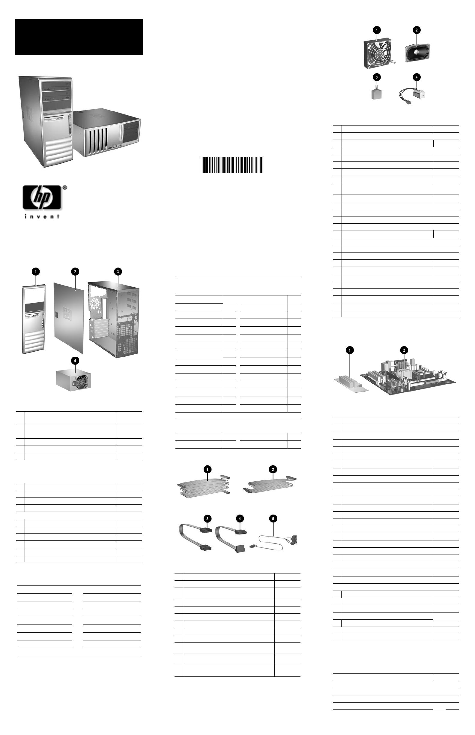
Miscellaneous Parts
1
Chassis fan 392412-001
2 Speaker 392413-001
3 Hood sensor 392417-001
4 Solenoid lock with cable 392416-001
* PCI latch kit 339808-005
* 5.25” Bay bezel blank 335937-005
* Diskette drive bay bezel blank 336581-005
* Diskette drive bay bezel 371119-001
* Diskette drive bay bezel blank, (unpainted, for Blue
Angel only)
392407-001
* Heatsink with thermal grease and alcohol pad 435920-001
* Power switch holder (use with 392285-001) 336156-005
* Mouse, 2-Button, PS/2 with scroll wheel 390937-001
* Mouse, 2-Button, USB, optical with scroll wheel 390938-001
* Mouse, 2-Button, USB, with scroll wheel 323615-005
* Rubber foot (4 ea) 336445-005
* Drive Key II, 256 MB 372889-001
* Real-time-clock battery 153099-001
* Port control cover 340400-005
* Second Serial Port 392414-001
* PCI extender card tray 392418-001
* Card guide 371117-001
* Front I/O device mounting bracket 371118-001
* Kensington cable lock 370856-001
* HP Business PC Security Lock (without cable) 335808-005
* HP Business PC Security Lock (with cable) 335809-005
* DVI to VGA adapter 202997-005
*Not shown
Standard and Optional Boards
1
PCI extender card 391084-001
2
System board with alcohol pad and thermal grease 380356-001
Memory Modules
* 256 MB/533 MHz FSB
393392-001
* 512 MB/533 MHz FSB
393393-001
* 1.0 GB/533 MHZ FSB
393394-001
* 256 MB/667 MHz FSB
396519-001
* 512 MB/667 MHz FSB
396520-001
* 1.0 GB/667 MHz FSB
398038-001
Intel Pentium 4 Processors with alcohol pad and thermal grease
* 2.8 GHz\800 MHz FSB, 1MB cache, 521 394643-001
* 3.0 GHz\800 MHz FSB, 1MB cache, 531 394642-001
* 3.2 GHz\800 MHz FSB, 1MB cache, 541 394812-001
* 3.0 GHz\800 MHz FSB, 2MB cache, 630 392273-001
* 3.2 GHz\800 MHz FSB, 2MB cache, 640 384786-001
* 3.4 GHz\800 MHz FSB, 2MB cache, 650 384787-001
* 3.6 GHz\800 MHz FSB, 2MB cache, 660 392272-001
* 3.8 GHz\800 MHz FSB, 2MB cache, 670 392271-001
Intel Pentium D Processors with alcohol pad and thermal grease
* 2.8 GHz\800 MHz FSB, 2x1MB cache, 820 392419-001
Intel Celeron D Processors with alcohol pad and thermal grease
* 2.66 GHz\533 MHz FSB, 256KB cache, 331 391940-001
* 2.8 GHz\533 MHz FSB, 256KB cache, 336 391941-001
Other Cards
* Intel Pro/1000 NIC 314901-005
* ATI PCI-E DVI/S-Video graphics, 128 MB 361266-001
* Quadro NVS 280 PCI graphics, 64 MB 351384-005
* Quadro NVS 280 PCI-E graphics, 64 MB 365934-001
* DVI ADD 2 graphics card 361265-001
* PCI Modem, worldwide 361286-021
* 1394, FH bracket 361552-001
*Not shown
Miscellaneous Screw Kit (not illustrated)
Miscellaneous screw kit 393956-001
6-32x.250 TF, HI/TP W/SERR, 6 ea
6-32x.187 Tamper-resistant, T15, 2 ea
Plastite, Flathead, Phillips, 4 ea
Plastite 8X5/16L, .185DX.03 SHLDR, 2 ea

