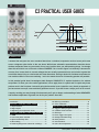
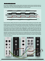
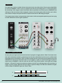
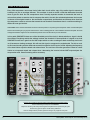
Joranalogue Compare 2 is a dual window comparator and logic module designed for audio rate and logic applications. Each channel features a voltage comparator with adjustable window size and offset, allowing for precise comparison of incoming signals to a defined range. The module also includes various logic functions (AND, OR, XOR, and FF) for combining and manipulating gate signals. With its versatile capabilities, Compare 2 is suitable for creating PWM waves, phase-shifted sawtooth waves, bitcrushing effects, and a wide range of experimental sound design and logic-based patches.
Joranalogue Compare 2 is a dual window comparator and logic module designed for audio rate and logic applications. Each channel features a voltage comparator with adjustable window size and offset, allowing for precise comparison of incoming signals to a defined range. The module also includes various logic functions (AND, OR, XOR, and FF) for combining and manipulating gate signals. With its versatile capabilities, Compare 2 is suitable for creating PWM waves, phase-shifted sawtooth waves, bitcrushing effects, and a wide range of experimental sound design and logic-based patches.


-
 1
1
-
 2
2
-
 3
3
-
 4
4
-
 5
5
-
 6
6
-
 7
7
-
 8
8
-
 9
9
-
 10
10
-
 11
11
-
 12
12
-
 13
13
-
 14
14
-
 15
15
-
 16
16
-
 17
17
-
 18
18


Joranalogue Compare 2 is a dual window comparator and logic module designed for audio rate and logic applications. Each channel features a voltage comparator with adjustable window size and offset, allowing for precise comparison of incoming signals to a defined range. The module also includes various logic functions (AND, OR, XOR, and FF) for combining and manipulating gate signals. With its versatile capabilities, Compare 2 is suitable for creating PWM waves, phase-shifted sawtooth waves, bitcrushing effects, and a wide range of experimental sound design and logic-based patches.
Ask a question and I''ll find the answer in the document
Finding information in a document is now easier with AI
Other documents
-
 Befaco Pony VCO User manual
-
SRS SR620 Owner's manual
-
Elenco EP130 Owner's manual
-
Silicon Labs SiM3L1xx Reference guide
-
 Erica Synths EDU DIY EG User manual
-
Freescale Semiconductor MC9S12VR64 Reference guide
-
 Erica Synths Hexinverter VCNO User manual
-
NXP S12ZVM Reference guide
-
 Bazille U-he Modular PD & FM Synthesizer User manual
-


