2/6
(11) Safety training/practice
(12) Occupational health (Medical examinations
(anterior part of the eye and ocular fundus))
(13) Other measures to prevent any interference
due to laser radiation (system protective casing,
safety inspections, etc.)
For Safe Use of Laser Products
3. Power Supply, Connection and Wiring
4. Interlock
5. Emission Direction
6. Dust and Gas Generated during Marking
7. Other
1. Power Supply, Connection and Wiring
2. Operating Environment
3. Work materials
5. Storage
6. Packing and Transporting
Notes on Operation
1.EU directives and UK legislations
Applicable Standards
EMC Standards
Safety Standards
The product is equipped with the interlock
function.Set the terminal of the input terminal block
[EMERGENCY A] (emergency stop input A) or
[EMERGENCY B] (emergency stop input B) to
open (OPEN) to forcibly close the shutter inside the
marker head and stop the laser emission.
When constructing an interlock system according
to Category 3 indicated in International Standards
ISO13849-1 (JIS B 9705-1) (classification of the
safety-related parts of a control system in respect
to their resistance to faults and their subsequent
behavior under the fault condition), use the
interlock terminal.
Do not store the product in an environment
described below.
• Storage temperature: -10 to 60 C(Non
condensation or freezing)
•
Storage humidity: 35 to 85% RH (No condensation)
• Outdoor or area subject to direct sunlight
• Area where corrosive gas, flammable gas, oil or
mist may be present
• Area that is constantly vibrating or subject to
startling vibration
• Very dusty area
The aforementioned points do not guarantee any
unforeseen situations that may arise from storing of
the product.
• To prevent power supply noise or radiant noise
from occurring, be sure to implement measures
against noise, such as a spark killer, at the
locations where a surge can occur, such as the
point of contact with the motor used for
surrounding devices.
• Refrain from using a cellular phone as it may
cause the laser marker to malfunction.
Follow the instructions below when using this
product with gold, silver, copper, or other highly
reflective materials. Reflected beams may damage
the marker head.
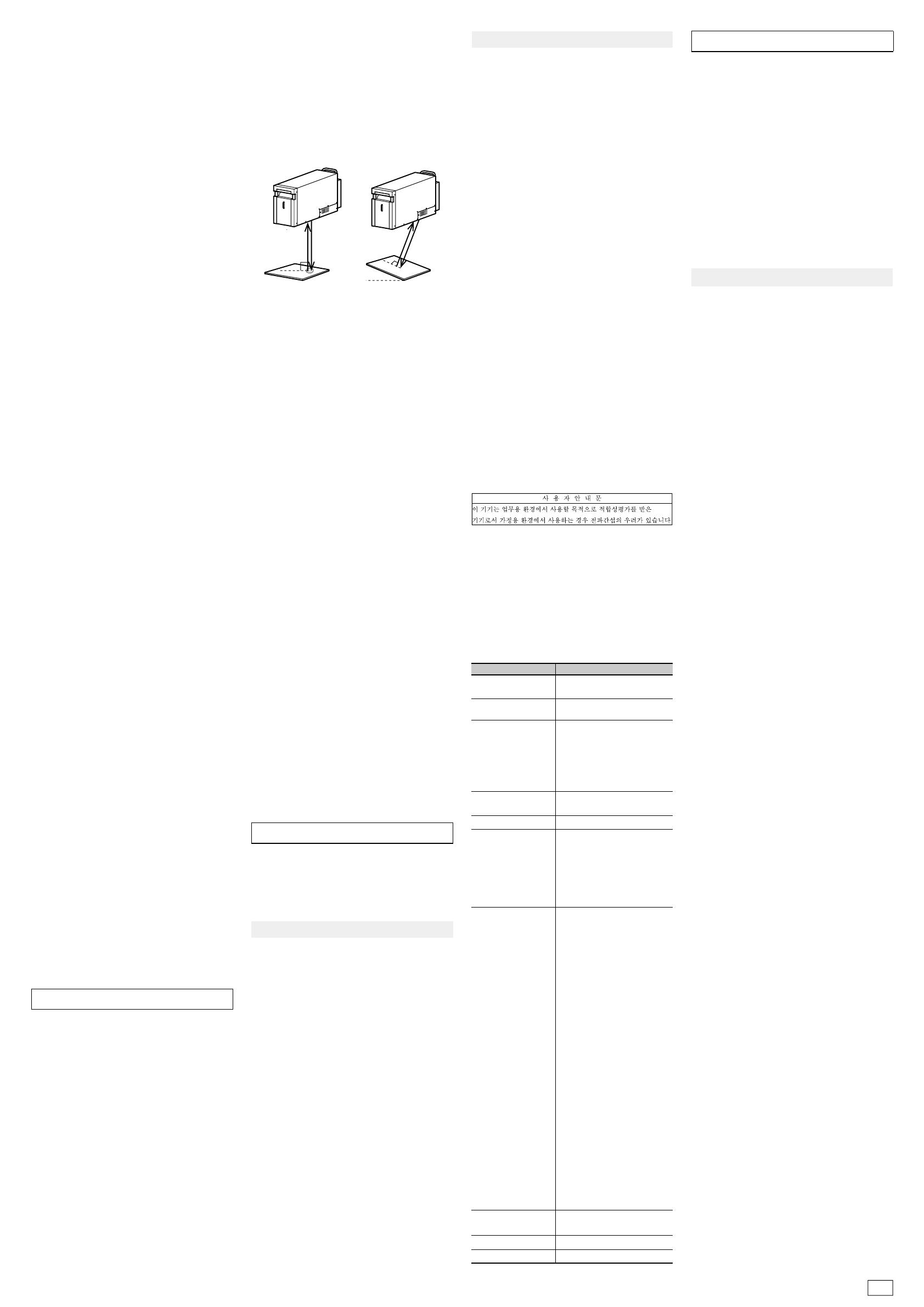
(1) For a work positioned horizontally to the
marker, do not mark within φ6 mm of the center
of the marking area.
(2) If the marking surface of the work is slanted or
curved, ensure that the specular reflection beam
is not reflected back into the marker head.
Please consult with our sales center when using
this product within these conditions.
The product assumes laser emission in the
downward direction. When setting the emission
direction to a direction other than downward, at
your own risk, please thoroughly implement safety
measures, as well as protective measures to
prevent dust from sticking to the cover glass.
Dust or gas generated during marking can cause
damage to the laser oscillator or the optical system.
Be sure to protect the laser marker by collecting
the dust or gas generated during marking.
When using a suction duct to suck in fine particles,
such as metal, oxidized and carbide material,
generated during marking, welding, cutting or other
processes, use a duct with straight interior walls
with which fine particles are hard to accumulate,
and install the duct so that fine particles do not
accumulate. Furthermore, periodically clean the
inside of the duct to prevent fine particles
from accumulating and to prevent a dust explosion.
• Do not disassemble, repair, modify, change the
shape by pressure, or incinerate this product.
• When disposing of the product, follow the
instructions of the local government and other
authorities and dispose of it as industrial waste.
• Connect the dedicated products (marker head,
controller and cable). Use of non-dedicated
products may lead to malfunction or failure.
• If you feel a sense of error, immediately stop
using the product and turn off the power supply,
and contact your OMRON representative.
• Do not move the product with the cable still
attached.
• Do not cut the fiber cable. If the fiber cable is
cut accidentally, please stop using the product
and consult your OMRON representative.
Observe the following points to prevent the product
from becoming inoperative or malfunctioning, or to
avoid adverse effects on its performance or device.
• Never bundle the marker head control cable and
the marker head power supply cable together
with 200/100 [VAC] power wires or the power
wire or control wire of the AC motor, AC servo
motor, or electromagnetic valve, etc. that is
being used on your system.Bundling them
together will cause noise to enter the galvanom-
eter control cable and the I/O cable for the
external control device, which may result in a
laser marker malfunction.
• If there is a surge in the power supply line,
connect a surge absorber depending on the
operating environment.
This product is a precision machine.Please
carefully observe the following points to avoid
damaging the product if you are packing and
transporting the roduct. When transporting the
product, use the packing materials that were used
at the factory setting by OMRON.
These requirements do not guarantee that all
machinery and equipment with this product
incorporated satisfy the requirements of EMC.
Manufacturers of the machinery and equipment are
responsible for verifying the compatibility of the
product with all the machinery and equipment.
EN61010-1 "Safety requirements for electrical
equipment for measurement, control, and laboratory
use - Part 1: General requirements" EN60825-1
"Safety of laser products - Part 1: Equipment
classification and requirements"
• Install in a place with an altitude of 3000 m or
less.
• Install indoors.
• The laser marker is a class 4 product. It is your
responsibility to build your own safety system
when using the product.
Although JIS C6802-compliant safety measures are
incorporated in this product, the safety measures
can be effective only when theuser of the product
understands the functions of these measures.Ac-
cordingly,pleasekeepinmindthatJIS
C6802-compliantproducts are products in which the
safety measures specified by JIS C6802 are
incorporated, and that the products, on their own,
arenot necessarily safe.
This product is categorized as class 4 based on
the JIS C6802
classification.The product incorporates the
function of the safetymeasures based on JIS
C6802 for the protective casing of the laser
oscillator part, cover interlock, remote interlock
(externalinterlock), key control, laser emission
display, opening label, classification label, warning
label, radiant output information
label, andoptical path cut-off (internal shutter).
Users of the product must use these functions to
apply the safety measures..
(1) Assignment of the laser safety manager
A laser safety manager is "a person who has
the sufficient knowledge required to evaluate
the danger of laser and to ensure safety and
who is responsible for the laser management,"
and is selected based on the level of knowl-
edge and experience inhandling laser devices
and prevention of interference due to laser
emission. Such a person must conduct tasks
equivalent to those of a laser device manager
based on the "Measures to prevent interference
caused by laser beams" issued by the Ministry
of Health, Labour and Welfare (
March 25, 2005
).
(2) Setting and management of the laser controlled
area
Separate the area from other areas and place a
sign to clearly indicate that the area is a laser
controlled area. Ensure that only authorized
personnel are allowed to enter the area.
Do not allow any hazardous materials such as
explosives and flammables to be brought into
the controlled area.
We have confirmed that this product satisfies the
requirements of EU directives and UK legislations
on the basis of the following requirements. Keep
the following requirements in mind when you use
This equipment is not intended for use in residential
environments and may not provide adequate protection
to radio reception in such environments.
• Make sure to attach the ferrite core to the
position specified in this INSTRUCTION
SHEET.
• When RS-232C or RS-422A serial port is
used, use a shielded twisted pair cable
(AWG24) equivalent to UL2464U-TKVVBS
(Tachii Electric Wire).
MX-9160-1M, 3M, and 5M (option) cables are
available for RS-232C to connect this product
with the PLC.
• Use a shielded cable 5m or less for connecting
to the Ethernet port.
• Use a shielded cable (AWG12 to 26) for
connecting to the removable terminals (for input
and output) and I/O connector.
• We do not guarantee that this product works
with any monitor, mouse, or keyboard. Check
the compatibility before selecting adevice.
(4)Use of remote interlock
When using this product, construct an interlock
system and surround the laser emission area
with protection in order to prevent radiation
exposure due to reflections from the object to
be marked or the surrounding area. Also, install
the controller in a locationnot being exposed to
laser beams.
(5) Management of the keys to operate the laser
devices
While a laser device is not in use, be sure to
remove the system key and pass it to the safety
manager for safekeeping in order to keep the
laser from being operated by unauthorized
personnel or without permission.
(6) Setting and verification of the beam path position
Setting the beam path position lower than the
eye level of a seated person or higher than the
eye level of a standing person can prevent laser
beams from getting in the eye accidentally.
(7) Handling of the end terminal
Take into consideration when no work exists
and terminate the laser radiation range with a
reflecting diffuser or absorber with appropriate
reflectance and heat resistance.
(8) Prevention of specular reflection
Do not use a specular reflector at the terminal.
(9) Cut-off and attenuation of beam
Be sure to install a protective enclosure
around the laser radiation range and
scattered beams in order to prevent
radiationexposure due to unexpected reflection
from the printed object and surrounding objects.
Scattered beams may exceed class 1 level.
Take measures to prevent laser exceeding
class 1 level from leaking through thegaps in
the protective casing joints.
(10) Inspection and maintenance of protective gear
(safety glasses, protective wear, flame-resistant
materials)
•
Wearing laser safety glasses for eye
protection in the laser controlled area must
be mandatory. Use laser safety glasses that
covers wavelength range of 1062 nm.
Do not look at a direct or reflected laser
beam even with safety glasses on. Safety
glasses are for protecting eyes from
scattered beams, not for protecting eyes
from direct or reflected beams.
•
Laser beam irradiation to the skin may
cause burns and irradiation to clothing may
cause it to burn.
Wear flame-retardant clothing with as little
skin exposure as possible.
Caution--use of controls or adjustments or
performance of procedures other than those
specified herein may result in hazardous radiation
exposure.
(3) Warning displays and signs
•
Post signs of danger and hazard of a laser
beam and its handling precautions in
locations where the signs are easily seen.
•
Post the name of the laser safety manager.
2. Installation Location
Do not install the product in any of the following
environments.
• Area with an ambient temperature that exceeds
the rated range
• Area with sudden temperature shift (area where
condensation can occur)
• Area with a humidity level that exceeds the 35
to 85% RH range
• Area subject to direct sunlight or near a heating
appliance
• Area where a ferromagnetic field or an intense
electric field is present
• Area where a carrier machine, etc. moves
• Area where corrosive gas or flammable gas is
present
• Area where dust, salt, or iron powder is present
• Area where water, oil or chemical splashes or
mist may be present
• Do not use a voltage that exceeds the rated
voltage or AC power source.
• Make the separate wiring for high-voltage line,
power wire and power to the product. Using the
same wire or duct will result in induction, which
then may cause malfunction or damage.
• Use the dedicated cables that are specified in
this document.
• Connect the controller power supply cable to a
3P outlet with grounding (D-class grounding). If
a D-class grounding is not used, there is a risk
of electric shock.
• Use SELV (Safety Extra Low Voltage) circuit for
all external circuits connected to this product.
SELV is an ungrounded circuit separated from
dangerous voltage by double insulation or higher
insulation, and it does not exceeds safe voltage
(peak 42.4 V or 60 V (DC)) even in single failure
condition.
■Low Voltage
2.UL standards
3.Regulation of perchlorate in California,
United States
4.Korean Radio Waves Act
When incorporating this product into a device that
complies with IEC60204-1 Standard | Safety of
machinery - Electrical equipment of machines - Part
1: General requirements, the exterior of the product
may need to be changed. Please purchase the
"Masking set" (MX-9190) that helps you easily
change the exterior of your laser marker.
We have confirmed and received certification that
this product satisfies the requirements of the UL
standard on the basis of UL 61010-1.
This product uses parts that contain perchlorate.
When you bring this product or a device with
this product incorporated into California in the
United States, the following statement must be
indicated on the individual packing box and
shipping box or ondocuments such as manuals or
MSDS included in the package.
Perchlorate Material - special handing may apply, see
http://www.dtsc.ca.gov/hazardouswaste/perchlorate/
This device has been evaluated for compatibility in
industrial use. When used in a household setting,
the device may cause radio interference.
■ Machinery
5. List of Applicable Standards
This product complies with the following standards.
Note that this product is not certified by safety
standards in countries and regions not listed.
When exporting the laser marker overseas alone
or incorporated into a machine or device, always
check the laws and standards in the country or
region the product is exported to.
Safety Measures for Class 4 Products
4. Maintenance Inspection
• If the cover glass of the marker head laser
irradiation port gets dirty, the laser output may
drop or a failure may occur. Do not use this
product while the cover glass is dirty.
• Do not use thinner, benzene, acetone or
kerosene items to clean the marker head or the
controller.Carefully remove dirt or dust on the
cover glass without scratching it by moistening
with cleaning agent a piece of cleaning paper
specifically for use on an optical device.
• Do not stack it on top of anything.
• Do not apply strong pressure on the cables.
• Pack and transport the product in the same
direction as it was installed.
• Protect the control panel, display panel,
connector and other parts from damage.
• Prevent condensation.
• Prevent the product from rolling over or falling,
or do not apply strong impact.
•
Refer to the previous item, "Storage," for details of
storing the product that is packed and is in transit.
The aforementioned items do not guarantee any
unforeseen situations that may arise from packing
or transporting of the product.
×
(1)
φ6
×
(2)
Applicable Standards
Details
FCC
Radio Act (Japan)
ICES
UL, CSA Standards
GB7247.1
GB Standards
Compliant with JIS C 6802 "Safety
Standards for Laser Products"
Not applicable (Corresponds to
facilities not requiring permission)
JIS (Japanese
Industrial Standards)
FDA (U.S. Food and
Drug Administration)
regulations
21 CFR1040.10 except for
deviations pursuant to Laser
Notice No. 50 "PART 1040
PERFORMANCE STANDARDS
FOR LIGHT-EMITTING
PRODUCTS"
Evaluated under IEC60825-1:2007
Korean Radio
Waves Act
Korean Radio Waves Act
Electromagnetic interference
(EMI)
•KN11
• KN61000-6-4
Electromagnetic susceptibility
(EMS)
• KN61000-6-2
EU directives /
UK legislations
2014/30/EU "EMC directive"
and Electromagnetic
Compatibility Regulations 2016
Electromagnetic interference
(EMI)
• EN61000-3-2 Class A
"Harmonic emission"
• EN61000-3-3 "Voltage
fluctuations and flicker"
• EN61000-6-4 "Emission
standard for industrial
environments"
Electromagnetic susceptibility
(EMS)
• EN61000-6-2 "Immunity
standard for industrial
environments"
2014/35/EU "Low Voltage
Directive" and Electrical
Equipment (Safety)
Regulations 2016
• EN61010-1 "Safety
requirements for electrical
equipment for measurement,
control, and laboratory use -
Part 1: General require-
ments"
• EN60825-1 "Safety of laser
products - Part 1: Equipment
classification and require-
ments"
UL61010-1, CAN/CSA C22.2
No.61010-1
RCM EN61000-6-4
ICES-001 Class A ISM equipment
47 CFR Part15 SubpartB
ClassA Digital Device


