Page is loading ...

OIL TRANSFER KIT
OWNER’S MANUAL
WARNING: Read carefully and understand all INSTRUCTIONS before operating.
Failure to follow the safety rules and other basic safety precautions may result in
serious personal injury.
Item # 28804

Page 1 of 16
Thank you very much for choosing a Roughneck™ Product! For future reference, please complete the
owner’s record below:
Model: _______________ Purchase Date: _______________
Save the receipt, warranty and these instructions. It is important that you read the entire manual to become
familiar with this product before you begin using it.
This machine is designed for certain applications only. The distributor cannot be responsible for issues arising
from modification. We strongly recommend this machine is not modified and/or used for any application other
than that for which it was designed. If you have any questions relative to a particular application, DO NOT use
the machine until you have first contacted distributor to determine if it can or should be performed on the
product.
For technical questions, please call 1-800-222-5381.
WARNING: Read carefully and understand all INSTRUCTIONS before operating. Failure to follow
the safety rules and other basic safety precautions may result in serious personal injury.
Save these instructions in a safe place and on hand so that they can be read when required. Keep
these instructions to assist in future servicing.
TECHNICAL SPECIFICATIONS
Model
28804
5:1 OIL PUMP KIT:
Pressure ratio
5:1
Air inlet working pressure
70-180 PSI
Max. air inlet pressure
180 PSI
Max. fluid pressure
870 PSI
Air motor effective diameter
4.25in.
Max. flow rate
11 GPM
Rigid suction tube length
35.5in (902mm)
Flexible suction tube length
6ft. (2m)
Air inlet
1/4in. FNPT
Oil outlet
3/4in. FNPT
Connection hose
1/2in. x 13ft.
HOSE REEL:
Inlet/ Outlet connection
1/2in.
Max. pressure
2000 PSI
Hose capacity
1/2in.I.D. x 50ft.
DIGITAL OIL CONTROL VALVE:
Inlet connection
1/2in.
Flow rate
0.3-9.2 GPM
Operating pressure range
7–1500 PSI
Max. operation temperature
140
Precision
±0.5%
Power source
one 3.6V ER14250 battery
FILTER AND REGULATOR:
Inlet/ Outlet
1/4in.
Pressure range
0.05-0.85mpa

Page 2 of 16
GENERAL SAFETY REGULATIONS
WARNING: Read and understand all instructions.
WARNING: The warnings, cautions, and instructions discussed in this instruction manual
cannot cover all possible conditions or situations that could occur. It must be understood by the
operator that common sense and caution are factors that cannot be built into this product, but must be
supplied by the operator.
1. Keep the work area clean and dry. Damp or wet work areas can result in injury.
2. Keep children away from work area. Do not allow children to handle this product.
3. Store idle equipment. When not in use, tools and equipment should be stored in a dry location to
inhibit rust. Always lock up tools and equipment, and keep out of reach of children.
4. Use the right tool for the job. Do not attempt to force small equipment to do the work of larger
industrial equipment. There are certain applications for which this equipment was designed. It will do the
job better and more safely at the capacity for which it was intended. Do not modify this equipment, and
do not use this equipment for a purpose for which it was not intended.
5. Use proper eye protection when assembling and using the kit.
6. Check for damaged parts. Before using this product, carefully check that it will operate properly and
perform its intended function. Check for damaged parts and any other conditions that may affect the
operation of this product. Replace damaged or worn parts immediately.
7. Do not overreach. Keep proper footing and balance at all times to prevent tripping, falling, back injury,
etc.
8. DO NOT use the equipment when tired or under the influence of drugs, alcohol, or medication.
A moment of inattention while operating this equipment may result in serious personal injury.
9. Industrial applications must follow OSHA requirements.
SPECIFIC OPERATION WARNINGS
WARNING: The included pump mainly provides power during oil transportation. Any other use can
cause unsafe operating conditions and result in component rupture, fire or explosion, which can cause
serious injury, including fluid injection.
WARNING: To prevent personal injury, perform the Pressure Relief Procedure before and after
operating the pump and before performing any disassembly or assembly.
WARNING: Failure to follow these warnings could result in serious personal injury or even death.
1. EQUIPMENT MISUSE HAZARD: Equipment misuse can cause the equipment to rupture or malfunction
and result in serious injury.
This equipment is for professional use only.
Read all instruction manuals, tags, and labels before you operate this equipment.
Use the equipment only for its intended purpose. If you are not sure, call the distributor.
Do not modify this equipment. If you need to replace the parts, use standard parts or components.
Check equipment daily. Repair or replace worn or damaged parts immediately.
Do not exceed the maximum working pressure of the lowest rated component in your system.

Page 3 of 16
Do not misuse this equipment to pump fluids and solvents which may cause damage to the wetted
parts of the equipment. Refer to instructions of the manufacturers of the fluids and solvents.
Handle hoses carefully. Do not pull on hoses to move equipment.
Route hoses away from traffic areas, sharp edges, moving parts, and hot surfaces.
Wear heat insulated gloves when operating the pump.
Do not move or lift pressurized equipment.
Comply with all applicable local, state, and national fire, electrical, and safety regulations.
2. SKIN INJECTION HAZARD: Fluid from the dispensing valve, leaks, or ruptured components can inject
fluid into your body and cause extremely serious injury. Fluid splashed in the eyes or on the skin can also
cause serious injury. If a fluid injection injury occurs, GET IMMEDIATE SURGICAL TREATMENT. Do not
treat it as a simple cut.
Do not point the dispensing valve at anyone or at any part of the body.
Do not put your hand or fingers over the end of the dispensing valve.
Do not stop or deflect leaks with your hand, body, glove or a rag.
Do not use oil that has been polluted or soiled.
Use only extensions and no-drip tips which are designed for use with your dispensing valve.
Follow the Pressure Relief Procedure in the OPERATION INSTRUCTIONS section if the fitting
coupler clogs and before you clean or service this equipment.
Tighten all fluid connections before operating the equipment.
Check the hoses, tubes, and couplings daily. Replace worn or damaged parts immediately. Do not
repair high-pressure couplings; you must replace the entire hose.
3. MOVING PARTS HAZARD: Moving parts, such as the air motor piston, can pinch or amputate your
fingers.
Keep clear of all moving parts when you start or operate the pump.
Before you service this equipment, follow the Pressure Relief Procedure in the OPERATION
INSTRUCTIONS section to prevent the equipment from starting unexpectedly.
Before operating the pump, make sure no moving parts are exposed to the outside.
Never operate the pump with the warning plate or the identification plate removed. These
plates serve as shields to protect your fingers from pinching or amputation by moving parts inside
the pump.
4. FIRE AND EXPLOSION HAZARD: Improper grounding, poor ventilation, open flames or sparks can cause
a hazardous condition and result in a fire or explosion and serious injury.
Ground the equipment and the object that is to be lubricated.
Do not run the pump without load.
If there is any static sparking or you feel an electric shock while using this equipment, stop
dispensing immediately. Do not use the equipment until proper grounding is established or any other
problem is identified and solved.
Provide fresh air ventilation to avoid the buildup of flammable fumes from solvents or the fluid being
dispensed.
Keep the dispensing area free of debris, including solvents, rags, and gasoline.
Do not smoke in the dispensing area.

Page 4 of 16
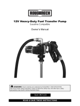
INSTALLATION
Typical installation refers to Fig.1.
Fig. 1
NOTE: The above typical installation is only for reference. It may be different from your actual system design.
WARNING: If this is a new installation, or if the oil in the lines is contaminated, flush the lines before you
install the kit. No impurities or contaminant are allowed to enter the kit.
WARNING: To reduce the risk of serious injury, the pressure release should be concerned. Please
follow the Pressure Relief Procedure in OPERATION INSTRUCTIONS section for the release process.
WARNING: Before operating the pump, check the grounding of whole system to avoid the risk of fire and
explosion.
To reduce the risk of static sparking, effectively ground all of this equipment.
Pump: Refer to Fig.1. Use ground wire and clamp as shown in Fig. 1. Remove the ground screw 1.
Connect the ground wire 2 to a true earth ground by inserting the terminal end of ground wire 2 through
the eye of the ring. Fasten the ground screw 1 back onto the pump and tighten securely.

Page 5 of 16
Air and fluid hoses: Make sure they are effectively grounded.
Air compressor: Follow the manufacturer's instruction to ground it.
Control valve: Use proper grounding wire to connect it to the pump. Always keep the metal part of the
control valve connected with the grounding equipment.
Oil Barrel: Use a barrel that can meet the local standard and ground it properly. A metal barrel can be
put directly on a surface of an electrical conductor that is properly grounded.
Other components: Ensure all parts are properly grounded to avoid risk of electrical shock.
WARNING: Always keep effective grounding when working or releasing pressure.
NOTE: Use oil resistant pipe sealant or Teflon® Tape on all fitting threads.
1. INSTALLATION OF OIL PUMP KIT
①. Secure the bracket (part# 4 of oil pump kit) to the wall using the dowels (NOT INCLUDED) at a height
appropriate for the tank’s dimension. Make sure that the wall is solid and thick enough for the dowels. Do
not interfere with hydraulic tubes or electric lines.
②. Secure the pump (part# 1 of oil pump kit) to the bracket (part# 4 of oil pump kit).
③. Connect the flexible suction tube (part# 6 of oil pump kit) to the pump using the clamp provided.
. Connect the rigid suction (part# 8 of oil pump kit) to the other end of the flexible suction tube (part# 6 of oil
pump kit) using the elastic clamp provided.
. Put the bung adapter (part# 7 of oil pump kit) into the drum hole.
. Put the rigid suction tube (part# 8 of oil pump kit) into the pump and secure it in place.
. Connect the pump to the hose reel with the 13ft. connection hose.
. Install the air filter and regulator to the air inlet of the pump with the adapter attached.
. Make sure the air supply valve is closed before connecting the air supply line with air filter and regulator.
2. INSTALLATION OF HOSE REEL
WARNING: Before mounting the hose reel, ensure that the supply line pressure does not exceed the
maximum working pressure of the hose reel.
Unpack and inspect reel for damage. Turn by hand to check for smooth operation. Check for completeness.
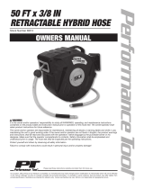
Position the reel on the floor, wall or ceiling. Secure into place using four mounting bolts (NOT INCLUDED).
See Fig. 2.
NOTE: Depending on where the reel is placed, it may be necessary to adjust the hose bumper and guide arm
to use the hose properly. See the instructions on the next page to adjust the hose bumper and reposition the
guide arm.
Fig.1 Ground the pump
1. Ground Screw
2. Ground Wire

Page 6 of 16
3. INSTALLATION OF DROP TRAY
Use one or two bolts and nuts (NOT INCLUDED) to secure the drop tray.
4. INSTALLATION OF CONTROL VALVE
Apply appropriate thread sealant around the male thread of flexible spout, and then screw the flexible
spout to the meter.
Assemble the rubber cover to the meter.
Apply appropriate thread sealant around the male thread of hose reel, then connect the male thread into
the female thread of oil inlet of the control valve, and fix them together.
Turn on all check valves of oil system.
Press the trigger to drain enough oil to make sure the oil system is completely cleaned. See
“OPERATION INSTRUCTIONS” section for the control valve operation.
NOTE: To ensure the meter accuracy, purge all air out from the fluid lines and control valve before using
them.
OPERATION INSTRUCTIONS
WARNING:
Never operate the meter with the plastic cover removed. The cover protects the meter from damage
due to impact. Meters are sealed in the factory to keep moisture and dirt away.
Flush the lines before you install this equipment in the system to prevent line contamination, or it can
cause equipment malfunction or damaged.
To reduce the risk of a serious bodily injury, including fluid injection, never exceed the maximum working
pressure of the kit you are using or of the lowest rated component in your system.
1. PRESSURE RELIEF PROCEDURE
WARNING: Skin injection hazard: The equipment stays pressurized until pressure is manually relieved.
To reduce the risk of serious injury from pressurized fluid, fluid from the valve or splashing fluid, follow this
procedure whenever you:
Are instructed to relieve pressure
Check, clean or service any system equipment
Install or clean dispensing devices
(1) Pressure relief procedure
Turn off the air supply to the pump.
Hold a metal part of the control valve firmly to a grounded metal waste container and point the valve
outlet toward the waste container, then trigger the control valve to relieve the fluid pressure.
Open any bleed-type master air valves and fluid drain valves in the system.
Floor Mounting
Wall Mounting
Ceiling Mounting
Fig. 2

Page 7 of 16
Leave the drain valve open until you are ready to pressurize the system.
(2) Clean the obstruction in the oil system, when any of the following cases occurs:
Problem on control valve, flexible hose, rigid tube or manual/auto tip.
Pressure can not be relieved completely after above procedures are done.
It takes more than 5 seconds to relieve the pressure thoroughly.
2. OPERATION
WARNING: Follow the instructions in PRESSURE RELIEF PROCEDURE before each operation.
①. Check reel for correct operation by slowly pulling out the hose. A “clicking” noise will be heard every half
revolution of the drum.
②. To latch the reel, pull out the hose and allow it to retract after hearing the first second or third “click”.
③. To unlatch, slowly pull out the hose until the “clicking” noise stops, then let the hose retract until the hose
stop rests against the hose guide. Note: To avoid damage to the reel, always hold on to the hose while it is
rewinding.
. Grab the trigger (part# 1-4 of control valve) gently, and then the control valve and the pump start to work.
. Keep the trigger lock (part# 1-3 of control valve) squeezed and depress the trigger lock (part# 1-3 of
control valve) to keep the control valve on.
. Disengage the trigger lock (part# 1-3 of control valve) and release the trigger lock (part# 1-3 of control
valve) to stop dispensing.
. Place the control valve through the hook of drop tray and let the oil drip to the poly tray.
3. ADJUSTMENTS FOR HOSE REEL
(1) Adjusting spring tension
If necessary, adjust spring tension on reel by adding or removing wraps of hose from spool, one wrap at a
time, until desired tension is obtained.
①. Pull out the hose until the latch pawl is engaged.
②. Loosen the stopper (part# 46 of hose reel), then add wraps or decrease the wraps as needed. Add wraps
to increase tension. Remove wraps to decrease tension.
③. Tighten the stopper (part# 46 of hose reel), and adjust stopper position if necessary.
CAUTION: Do not exceed the winding mechanism’s spring capacity when adding wraps of hose. Add just
enough wraps of hose to achieve the desired tension. The winding mechanism will be damaged if spring is
over-tensioned.
(2) Adjusting the hose bumper
①. Pull out the hose until the latch pawl is engaged.
②. The stopper (part# 46 of hose reel) can be adjusted by loosening the slotted screws. Slide the stopper to
the desired position and tighten the screws before pulling hose to disengage the latch pawl.
(3) Removing and positioning guide arm
According to each mounting application, recommend Guide Arm positions.
①. Pull out hose until the latch pawl is engaged.
②. Remove stopper (part# 46 of hose reel) by removing the slotted screws.
③. Disengage the latch pawl while maintaining a firm hold on spool. Turn the spool hand over hand
approximately two or three circles in the direction of the drive spring until tension is removed.
. Remove the nuts and washers holding the guide arm and shift to base.
. Rotate the guide arm and adjust it to any of the three positions hinted. See Fig. 3

Page 8 of 16
. Replace and tighten the nuts and washers.
. Tighten the drive spring by turning the spool two or three circles and engage the latch pawl.
. Pull the hose through the roller opening in the guide arm and replace the stopper.
4. OPERATION OF CONTROL VALVE
(1) LCD DISPLAY
INDICATIONS: See the following displaying illustration of the LCD panel.
Fig. 4 LCD panel displays region
Partial register
Measurement exceeds the maximum value will become zero and re-measure.
Indication of unit of measurement (L, GAL, PT, QT)
Accumulated total
Battery condition (Low-power alarm device is built in.)
(2) OPERATIONAL FUNCTIONS
The control valve features two keys (MENU and RESET).
A. Setting measurement unit
Solution 1
Press “MENU” and “RESET” simultaneously and hold for about 5 seconds to enter the unit set mode.
Press "RESET" to select the unit.
When desired measurement unit is displayed, press “MENU” and hold about 1 second or the digit stops
blink to quit the setting mode.
Solution 2
Fig. 3

Page 9 of 16
①. Move the flashing display to Zone by pressing “MENU”, then press “RESET” to choose measurement
unit;
②. Press “MENU” over 3 seconds to exit the setting mode.
B. Resetting the accumulated total
Press “MENU” for 10 seconds, the accumulated total will be reset to be “0”.
C. Displaying current correction factor
Press “MENU” and “RESET” simultaneously and hold for 2 seconds. The display shows the correction factor.
(3) CALIBRATION PROCEDURE
A. Procedure for entering the correction factor directly
Wait for the control valve to go to standby.
Press the “MENU” key. Keep it pressed until the digit flashes in Zone . Press the “RESET” key to
choose the right digit from 0 to 9. Press the “MENU” key to go the next digit so that the Actual Value can
be input.
Make sure the correction factor is right and then press the “MENU” key. Keep it pressed until calibration is
finished and the factor is saved. The control valve will then return to standby.
B. Modify the correction factor in field
Press the “RESET” for 1 second, Zone displays “0.00”.
Start dispensing into a measuring glass.
Stop dispensing when over 5 liters of volume is reached, then check the actual dispensed value. The
volume that is displayed on the LCD is the Display Value, not the Actual Value.
Press the “MENU” key. Keep it pressed until the digit flashes in Zone . Then press the RESET key to
choose the right digit from 0 to 9. Press the “MENU” key to go the next digit so that the Actual Value can
be input.
Make sure the Actual Value is input right and then press the “MENU” key. Keep it pressed until calibration
is finished and the factor is saved. The meter will then return to standby.
(4) BATTERY REPLACEMENT
If Voltage is too low, low-power alarm device will be activated and light flashes in Zone
When the LCD panel displays nothing or light flashes in Zone , the battery should be replaced. Follow the
steps below to replace new battery.
Open the battery cover (part# 3-11) with a flat screwdriver.
Remove the old battery. Discard the battery in accordance with local laws and ordinances.
Insert a 3.6V ER14250 battery into the battery compartment. Install the battery according to the direction
of polarity “+” & “-” indicated and insert the end of anode “+” first.
Place back the battery cover (part# 3-11).
TROUBLE SHOOTING
WARNING: Relieve pressure before you check or service any system equipment.
Oil pump:
Problem
Possible Cause
Corrective Action
Inadequate air supply pressure or
restricted air lines
Increase air supply and/or
clear restriction
Closed or clogged control valves
Open and/or clean
Clogged fluid line, hose, valve, or
other accessory
Relieve pressure
Clear obstruction
Pumps fails to
operate
Damaged air motor
Assess damage, and service air
motor

Page 10 of 16
Exhausted fluid supply
Refill and re-prime or flush
Continuous air
exhaust
Worn or damaged air motor
gasket or seal
Assess wear or damage, and
service air motor
Exhausted fluid supply
Refill and re-prime or flush
Worn pump seals
Replace pump seals
Erratic pump
operation
Damaged hose
Replace hose
Worn piston seal
Replace piston seal
Worn seals
Replace seals
Pump operates, but
output low
Clogged fluid line, hose, valve, or
other accessory
Relieve pressure
Clear obstruction
Leaking from
muffler plates
Worn throat seal
Replace throat seal
Oil control valve:
Problem
Possible Cause
Corrective Action
Slow or no fluid flow
1. Filter is clogged
2. Pump pressure is low
3. Shut-off valve is not fully open
4. Foreign material is jammed in
the metering element
1. Clean or replace the filter (part# 1-13
of control valve)
2. Relief the pressure
3. Fully open the shut-off valve
4. Loosen swivel fitting (part# 1-1 of
control valve), and clean up foreign
material
Oil leaks from swivel
1. Swivel is loose
2. O-ring is worn or damaged
1. Tighten the swivel (part# 1-1 of
control valve)
2. Replace the o-ring (part# 1-14 of
control valve)
Oil drips from nozzle
Nozzle is damaged or obstructed
Inspect the nozzle for damage or
obstructions, and replace if damaged
Valve leaks
O-rings or valve seat are worn or
damaged
Replace the o-rings (part# 1-5 of control
valve) and/or the valve seat (part# 1-10
of control valve)
Leakage from meter
O-ring damaged
5. 1. Get the meter off from the dispense
system
6. 2. Take off the Rubber Protector
(part# 3-4 of control valve) and Front
Label (part# 3-6 of control valve)
7. 3. Remove four the socket head cap
screws (part# 3-8 of control valve)
on the cover of the meter
8. 4. Remove eight the hex bolts (part#
3-18 of control valve) on the bottom
of the meter
9. 5. Take off the seat( part# 3-10 of
control valve)
10. 6. Check the o-ring (part# 3-1 of control
valve), replacing the o-ring if it is
damaged
11. 7. After replacing the o-ring, assemble
the meter and fix it back to the
dispense system
No display
Battery out of power
Replace the battery
Wrong reading
Wrong correction factor
Follow “CALIBRATION PROCEDURE”
for right correction factor

Page 11 of 16
MAINTENANCE
CAUTION: Remove all tension before servicing. Hazards or unsafe practices MAY result in minor
personal injury, product or property damage.
WARNING: Before performing any service, always disconnect and lock out compressed air or
fluid, and remove all spring tension. Hazards or unsafe practices COULD result in severe personal
injury or death.
WARNING: User servicing of the reel is limited to replacing input/output hoses only. Refer all other
repairs to an authorized service person. Failure to do so can result in person injury and/or equipment damage
and may void the warranty.
Replacing the hose
To remove the hose
①. Pull out the hose leaving 2 to 3 feet on the spool. Engage the latch pawl.
②. Unthread the hose at the connection to the swivel tube.
③. Remove the hose.
To install the hose
①. Route the hose through the guide arm rollers and opening of the spool. Apply thread tape or sealant to
hose threads.
②. Screw hose fitting into threaded fitting on swivel. Tighten connection with a wrench on fitting. Install
stopper on working end of hose if required.
③. Disengage latch pawl and allow hose to retract.
Replacing the swivel
①. If the swivel leak, replace the O-ring or seal (#31) and washer (#30) by removing the lock washer (#40)
and the part of the swivel shift.
②. If the balls (#37) wear-out, replace by removing the lock washer (#40).
③. Replace the new seal by clipping the lock washer (#40). Replace the part of the swivel shift by clipping the
lock washer (#40).
Transportation
When the control valve is in transit, do not exposure the control valves with direct sunlight and avoid rain,
falling, corrosive substances, etc.
Storage
①. Store the control valve in a dry place with good ventilation. Do not expose it to excessive heat, humidity or
sunlight. Never let it touch any corrosive substances.
Fig. 5

Page 12 of 16
②. Store it out of the reach of children.
③. Always keep the pump at least 4 feet away from any heat source.
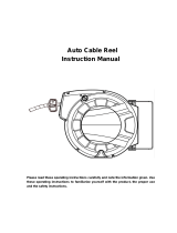
DIAGRAMS AND PARTS LIST
Part No.
Description
Qty.
Part No.
Description
Qty.
1
Oil pump
1
8
Rigid suction hose
1
2
Hose reel
1
9
Pump adapter
1
3
Oil Control Valve
1
10
3/4in. to 1/2in. Adapter
1
4
Drop tray
1
11
Adapter (male & male)
1
5
Filter and regulator
1
12
Bung adapter
1
6
Connection hose
1
13
Filter
1
7
Flexible suction hose
1
14
Wall bracket
1
2
1
3
4
5
6
7
8
10
9
12
14
13
11

Page 13 of 16
1. 17130503 Oil pump
Part No.
Description
Qty.
Part No.
Description
Qty.
1
Air motor cover
1
28
Rope pin
2
2*
Spring piece
2
29*
O-ring
1
3
Bracket
1
30
Rope shaft
2
4
Rope rocker
2
31*
Spring
2
5
Shaft
1
32*
O-ring
1
6*
Copper ring
1
33
Jar body
1
7
Air control center
1
34
Washer
2
8*
O-ring
1
35*
Steel wire
2
9
Right silencer
1
36
Adjustable screw
2
10*
U-seal
1
37*
Rubber gasket
2
11*
Sponge
2
38
Connect shaft
2
12*
O-ring
1
39*
Gasket
2
13*
O-ring
1
40
Quick plug
1
14
Piston
1
41
Oil outlet
1
15*
Circlip
1
42*
Rubber gasket
2
16
Suction tube
1
43
Bolt
2

Page 14 of 16
17*
O-ring
1
44
Bolt
12
18
Oil inlet valve
1
45
Bolt
1
21
Piston shaft
1
46
Adjustable nut
2
22
Left silencer
1
47
Nut
2
23
Transfer slipcover
1
48
Bung adapter
1
24
Shaft
1
49
Label
2
25
Screw
6
50*
O-ring
1
26*
O-ring
1
51
Steel ball
1
27
Piston
1
52
Steel ball
1
Wear parts
Part No.
Description
Qty.
Part No.
Description
Qty.
2*
Spring piece
2
26*
O-ring
1
6*
Copper ring
1
29*
O-ring
1
8*
O-ring
1
31*
Spring
2
10*
U-seal
1
32*
O-ring
1
11*
Sponge
2
35*
Steel wire
2
12*
O-ring
1
37*
Rubber gasket
2
13*
O-ring
1
39*
Gasket
2
15*
Circlip
1
42*
Rubber gasket
2
17*
O-ring
1
43
Bolt
2
50*
O-ring
1
2. M860154 Hose Reel
Part No.
Description
Qty.
Part No.
Description
Qty.
1
Nut
1
23
Bolt
4
2
Spring washer
1
24
Base
1
3
Washer
2
25
Double bolt
3

Page 15 of 16
4
Bolt
9
26
Spring core
1
5
Bracket arm
1
27
Spring
1
6
Washer
1
28
Drum
1
7
Ratchet
1
29
Swivel shaft
1
8
Washer
1
30
Washer
2
9
Lock washer
1
31
O-ring or seal
1
10
Click pulley
1
32
Washer
1
11
Nut
8
35
Swivel shaft
1
12
Lock washer
2
36
Bearing cover
1
13
Washer
4
37
Ball bearing
17
14
Shaft
1
38
Bearing washer
1
15
Key
1
39
Washer
1
16
Guide sub-plate
1
40
Lock washer
2
17
Drum
1
41
Bracket arm
1
18
Roller axle
2
43
Double bolt
1
19
Roller
2
44
Hose assembly
1
20
Roller
2
45
Clamp
1
21
Roller axle
2
46
Stopper assembly
1
22
Guide plate
1
47
Ratchet spring
1
3. 18123522 Digital Oil Control Valve
Part No.
Description
Qty.
Part No.
Description
Qty.
1-1
Swivel
1
3-5
Main Circuit Board
1
1-2
Handle
1
3-6
Front Label
1
1-3
Trigger lock
1
3-7
Screw
4
1-4
Trigger
1
3-8
Screw
4

Page 16 of 16
1-5*
O-ring
2
3-9*
O-ring
1
1-6
Screw
2
3-10
Seat
1
1-7*
Washer, flat
2
3-11
Battery cover
11
1-8
Cam
1
3-12
Spring
1
1-9
Rod
1
3-13*
Battery
1
1-10*
Seat
1
3-14
Screw
2
1-11
Washer
1
3-15
Shaft
2
1-12
Spring
1
3-16
Oval Gear
2
1-13*
Filter
1
3-17
Magnetic Rod
2
2
Adapter
1
3-18
Bolt
8
3-1*
O-ring
1
3-19*
Waterproof protector
2
3-2
Meter Holder
1
3-20*
Seal washer
4
3-3
Meter Cover
1
3-21
Washer
4
3-4
Rubber Protector
1
4
Nozzle with tip
1
PART#4 includes:
Part No.
Description
MH10002
Flexible nozzle
MT10002
Auto tip
Wear parts
Part No.
Description
Qty.
Part No.
Description
Qty.
1-5*
O-ring
2
3-9*
O-ring
1
1-7*
Washer, flat
2
3-13*
Battery
1
1-10*
Seat
1
3-19*
Waterproof protector
2
1-13*
Filter
1
3-20*
Seal washer
4
3-1*
O-ring
1
4. DT10001 Drop tray
Part No.
Description
Qty.
1
Steel stand
1
2
Poly tray
1
For replacement parts and technical questions, please call 1-800-222-5381.
WARRANTY
One-Year Limited Warranty
Distributed by
Northern Tool + Equipment Co., Inc.
Burnsville, MN 55306
NorthernTool.com
Made in China
/