Page is loading ...

Instructions
SD and XD Series
Hose Reels 313431L
EN
For dispensing air, water, antifreeze, windshield washer solvent, transmission fluid, oil and
grease. For professional use only.
Not approved for use in European explosive atmosphere locations.
A complete list of Models, including Maximum Working
Pressure, begins on page 2.
Table of Conents
Models . . . . . . . . . . . . . . . . . . . . . . . . . . . . . . . . . . . . 2
Warnings . . . . . . . . . . . . . . . . . . . . . . . . . . . . . . . . . . 5
Typical Installation . . . . . . . . . . . . . . . . . . . . . . . . . . 7
Installation . . . . . . . . . . . . . . . . . . . . . . . . . . . . . . . . 8
Maintenance . . . . . . . . . . . . . . . . . . . . . . . . . . . . . . 24
Parts SD Series . . . . . . . . . . . . . . . . . . . . . . . . . . . . 30
Parts XD Series; HS Models . . . . . . . . . . . . . . . . . 32
Parts XD Series; HN Models . . . . . . . . . . . . . . . . . 34
Kits . . . . . . . . . . . . . . . . . . . . . . . . . . . . . . . . . . . . . . 36
Technical Data . . . . . . . . . . . . . . . . . . . . . . . . . . . .41
Mounting Channel Dimensions . . . . . . . . . . . . . . .45
Notes . . . . . . . . . . . . . . . . . . . . . . . . . . . . . . . . . . . .51
Graco Hose Reel Warranty . . . . . . . . . . . . . . . . . .52
Graco Information . . . . . . . . . . . . . . . . . . . . . . . . .52
Important Safety Instructions
Read all warnings and instructions in this
manual. Save these instructions.
(HS Models)
(HP Models)
SD Series XD Series XD Series
(HN Models)
Patents
Community Design #001209712-001 (SD Series and XD Series only)

Models
2313431L
Models
SD Series (Part List page 30)
*Each HP Model hose reel shown in the tables below is available in several colors. The last character of each Model
No. indicates the hose reel color. For example: A = white, B = metallic blue, C = red, D = black, E = Mercedes blue, or
F = yellow. (Other color choices may be available from your Graco Distributor.) On the table below this last character
is represented by the generic # symbol. For example, to show the complete model number for a white HPL56# model
hose reel, the # symbol in the table is replaced with “A”. The complete model number is: HPL56A.
Model
No.* Size Type
Pressure
Rating
psi (bar) Media
Connection Size Line
Size
(inches)
Length
(feet)Inlet Outlet
HPL2D# 10 Bare 300 (20.7) Air/Water 3/8 npsm(m)
3/8 bspp(m)
1/2 npsm(f)
1/2 bspp(f) 3/8 50
HPL6D# 20 Bare 300 (20.7) Air/Water 1/2 npsm(m)
1/2 bspp(m)
1/2 npsm(f)
1/2 bspp(f) 1/2 50
HPL23# 10 Hose 300 (20.7) Air/Water 1/2 npsm(m)
1/2 bspp(m)
3/8 npt(m)
3/8 bspp(m)
3/8 bspt(m)
3/8 35
HPL25# 10 Hose 300 (20.7) Air/Water 1/2 npsm(m)
1/2 bspp(m)
3/8 npt(m)
3/8 bspp(m)
3/8 bspt(m)
3/8 50
HPL56# 20 Hose 300 (20.7) Air/Water 1/2 npsm(m)
1/2 bspp(m)
3/8 npt(m)
3/8 bspp(m)
3/8 bspt(m)
3/8 65
HPL33# 10 Hose 300 (20.7) Air/Water 1/2 npsm(m)
1/2 bspp(m)
1/2 npt(m)
1/2 bspp(m)
1/2 bspt(m)
1/2 35
HPL65# 20 Hose 300 (20.7) Air/Water 1/2 npsm(m)
1/2 bspp(m)
1/2 npt(m)
1/2 bspp(m)
1/2 bspt(m)
1/2 50
HPM3B# 10 Bare 2000 (138) Oil 1/2 npsm(m)
1/2 bspp(m)
1/2 npsm(f)
1/2 bspp(f) 1/2 35
HPM6D# 20 Bare 2000 (138) Oil 1/2 npsm(m)
1/2 bspp(m)
1/2 npsm(f)
1/2 bspp(f) 1/2 50
HPM33# 10 Hose 2000 (138) Oil 1/2 npsm(m)
1/2 bspp(m)
1/2 npt(m)
1/2 bspp(m)
1/2 bspt(m)
1/2 35
HPM65# 20 Hose 2000 (138) Oil 1/2 npsm(m)
1/2 bspp(m)
1/2 npt(m)
1/2 bspp(m)
1/2 bspt(m)
1/2 50
HPH1D# 10 Bare 5000 (344.7) Grease 3/8 npsm(m)
3/8 bspp(m)
3/8 npsm(f)
3/8 bspp(f) 1/4 50
HPH5D# 20 Bare 5000 (344.7) Grease 3/8 npsm(m)
3/8 bspp(m)
3/8 npsm(f)
3/8 bspp(f) 3/8 50
HPH15# 10 Hose 5000 (344.7) Grease 3/8 npsm(m)
3/8 bspp(m)
1/4 npt(m)
1/4 bspp(m)
1/4 bspt(m)
1/4 50

Models
313431L 3
HPH23# 10 Hose 4800 (331) Grease 3/8 npsm(m)
3/8 bspp(m)
1/4 npt(m)
1/4 bspp(m)
1/4 bspt(m)
3/8 35
HPH55# 20 Hose 4800 (331) Grease 3/8 npsm(m)
3/8 bspp(m)
1/4 npt(m)
1/4 bspp(m)
1/4 bspt(m)
3/8 50
Model
No.* Size Type
Pressure
Rating
psi (bar) Media
Connection Size Line
Size
(inches)
Length
(feet)Inlet Outlet

Models
4313431L
XD Series (Parts List page 32)
**Each HS or HN Model hose reel shown in the table below is available in either white, metallic blue or yellow. The
last character of each Model No. indicates the hose reel color. For example: A = white, B = metallic blue, F = yellow.
(Other color choices may be available from your Graco Distributor.) On the table below this last character is repre-
sented by the generic # symbol. For example to show the complete model number for a white HSL2D# model hose
reel, the # symbol in the table is replaced with “A”. The complete model number is: HSL2DA.
Model
No.** Size Type
Pressure
Rating
psi (bar) Media
Connection Size Line
Size
(inches)
Length
(feet)Inlet Outlet
HSL2D# 10 Bare 300 (20.7) Air/Water 1/2 npsm(m)
1/2 bspp(m)
3/8 npsm(f)
3/8 bspp(f) 3/8 50
HSL6D# 20 Bare 300 (20.7) Air/Water 1/2 npsm(m)
1/2 bspp(m)
1/2 npsm(f)
1/2 bspp(f) 1/2 50
HSL25# 10 Hose 300 (20.7) Air/Water 1/2 npsm(m)
1/2 bspp(m)
3/8 npt(m)
3/8 bspp(m)
3/8 bspt(m)
3/8 50
HSL33# 10 Hose 300 (20.7) Air/Water 1/2 npsm(m)
1/2 bspp(m)
1/2 npsm(m)
1/2 bspp(m)
1/2 bspt (m)
1/2 35
HSL56# 20 Hose 300 (20.7) Air/Water 1/2 npsm(m)
1/2 bspp(m)
3/8 npt(m)
3/8 bspp(m)
3/8 bspt(m)
3/8 65
HSL65# 20 Hose 300 (20.7) Air/Water 1/2 npsm(m)
1/2 bspp(m)
1/2 npt(m)
1/2 bspp(m)
1/2 bspt(m)
1/2 50
HSM3B# 10 Bare 2000 (138) Oil 1/2 npsm(m)
1/2 bspp(m)
1/2 npsm(f)
1/2 bspp(f) 1/2 35
HSM6D# 20 Bare 2000 (138) Oil 1/2 npsm(m)
1/2 bspp(m)
1/2 npsm(f)
1/2 bspp(f) 1/2 50
HSM33# 10 Hose 2000 (138) Oil 1/2 npsm(m)
1/2 bspp(m)
1/2 npt(m)
1/2 bspp(m)
1/2 bspt(m)
1/2 35
HSM65# 20 Hose 2000 (138) Oil 1/2 npsm(m)
1/2 bspp(m)
1/2 npt(m)
1/2 bspp(m)
1/2 bspt(m)
1/2 50
HSH15# 10 Hose 5000
(344.7)
Grease 3/8 npsm(m)
3/8 bspp(m)
1/4 npt(m)
1/4 bspp(m)
1/4 bspt(m)
1/4 50
HSH1D# 10 Bare 5000
(344.7) Grease 3/8 npsm(m)
3/8 bspp(m)
3/8 npsm(f)
3/8 bspp(f) 1/4 50
HSH5D# 20 Bare 5000
(344.7) Grease 3/8 npsm(m)
3/8 bspp(m)
3/8 npsm(f)
3/8 bspp(f) 3/8 50
HSH55# 20 Hose 4800 (331) Grease 3/8 npsm(m)
3/8 bspp(m)
1/4 npt(m)
1/4 bspp(m)
1/4 bspt(m)
3/8 50
HNL56# 20 Hose 300 (20.7) Air/Water 1/2 npsm(m) 3/8 npt(m) 3/8 65
HNL65# 20 Hose 300 (20.7) Air/Water 1/2 npsm(m) 1/2 npt(m) 1/2 50
HNM65# 20 Hose 2000 (138) Oil 1/2 npsm(m) 1/2 npt(m) 1/2 50
HNH55# 20 Hose 4800 (331) Grease 3/8 npsm(m) 1/4 npt(m) 3/8 50

Warnings
313431L 5
Warnings
The following warnings are for the setup, use, grounding, maintenance, and repair of this equipment. The exclama-
tion point symbol alerts you to a general warning and the hazard symbol refers to procedure-specific risk. Refer back
to these warnings. Additional, product-specific warnings may be found throughout the body of this manual where
applicable.
WARNING
FIRE AND EXPLOSION HAZARD
When flammable fluids are present in the work area, such as gasoline and windshield wiper fluid, be
aware that flammable fumes can ignite or explode. To help prevent fire and explosion:
• Use equipment only in well ventilated area.
• Eliminate all ignition sources, such as cigarettes and portable electric lamps.
• Keep work area free of debris, including rags and spilled or open containers of solvent and gasoline.
• Do not plug or unplug power cords or turn lights on or off when flammable fumes are present.
• Ground all equipment in the work area.
• Use only grounded hoses.
• If there is static sparking or you feel a shock, stop operation immediately. Do not use equipment
until you identify and correct the problem.
• Keep a working fire extinguisher in the work area.
EQUIPMENT MISUSE HAZARD
Misuse can cause death or serious injury.
• Do not operate the unit when fatigued or under the influence of drugs or alcohol.
• Do not exceed the maximum working pressure or temperature rating of the lowest rated system
component. See Technical Data in all equipment manuals.
• Use fluids and solvents that are compatible with equipment wetted parts. See Technical Data in all
equipment manuals. Read fluid and solvent manufacturer’s warnings. For complete information
about your material, request MSDS forms from distributor or retailer.
• Check equipment daily. Repair or replace worn or damaged parts immediately with genuine manu-
facturer’s replacement parts only.
• Do not alter or modify equipment.
• Use equipment only for its intended purpose. Call your distributor for information.
• Route hoses and cables away from traffic areas, sharp edges, moving parts, and hot surfaces.
• Do not kink or over bend hoses or use hoses to pull equipment.
• Keep children and animals away from work area.
• Comply with all applicable safety regulations.
SKIN INJECTION HAZARD
High-pressure fluid from dispense valve, hose leaks, or ruptured components will pierce skin. This may
look like just a cut, but it is a serious injury that can result in amputation. Get immediate surgical
treatment.
• Do not point dispense valve at anyone or at any part of the body.
• Do not put your hand over the end of the dispense nozzle.
• Do not stop or deflect leaks with your hand, body, glove, or rag.
• Follow Pressure Relief Procedure in this manual, when you stop spraying and before cleaning,
checking, or servicing equipment.

Warnings
6313431L
MOVING PARTS HAZARD
Moving parts can pinch or amputate fingers and other body parts.
• Keep clear of moving parts.
• Do not operate equipment with protective guards or covers removed.
• Pressurized equipment can start without warning. Before checking, moving, or servicing equipment,
follow the Pressure Relief Procedure in this manual. Disconnect power or air supply.
PRESSURIZED EQUIPMENT HAZARD
Fluid from the gun/dispense valve, leaks, or ruptured components can splash in the eyes or on skin and
cause serious injury.
• Follow Pressure Relief Procedure in this manual, when you stop spraying and before cleaning,
checking, or servicing equipment.
• Tighten all fluid connections before operating the equipment.
• Check hoses, tubes, and couplings daily. Replace worn or damaged parts immediately.
WARNING

Typical Installation
313431L 7
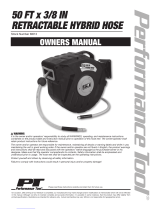
Typical Installation
Overhead-Mounted Hose Reel
Key:
A Main air supply line
B Pump air supply line
CAir filter
D Air regulator
E Bleed-type master air valve (required)
FPump
G Pump grounding wire (required)
H Fluid drain valve (required)
J Fluid shutoff valve
K Fluid line
L Hose reel fluid inlet kit
M Hose reel
N Dispensing valve
P Mounting channel/base
A ground wire (G), bleed-type master air valve (E) and
fluid drain valve (H) are required in your system installa-
tion. These components help reduce the risk of serious
injury, including electric shock and splashing in your eyes
or on the skin.
•The ground wire must be connected to the pump
grounding lug and to a true each ground according to
your local code.
•The bleed-type master air valve relieves air trapped
between this valve and the pump after the air is shut
off. Trapped air can cause the pump to cycle unexpect-
edly Locate the valve close to the pump.
•The fluid drain valve assists in relieving fluid pressure
in the displacement pump, hose and gun. Triggering
the valve to relieve pressure may not be sufficient.
FIG. 1: Typical Installation
03791
A
B
C
DE
F
G
K
H
J
N
M
P
L
J

Installation
8313431L
Installation
The typical installations shown in FIG. 1 is only a guide
for selecting and installing a hose reel system. The com-
ponents shown are the minimum requirements for all
systems. However, it is not an actual system design.
Contact your Graco distributor for assistance in design-
ing a system to suit your needs.
NOTE: The air and fluid accessories required for your
pump must be properly sized to that pump. Refer to your
specific pump manual for selecting pump accessories.
Air Line Components
Install the following components in the order shown in
FIG. 1, using adapters if necessary.
• Bleed-type Master Air Valve (E): locate down-
stream from the air regulator and for easy access
from the pump.
• Air Regulator (D): controls pump speed and outlet
pressure by adjusting the air pressure to the pump.
Locate the regulator close to the pump but upstream
from the bleed-type master air valve.
• Air Line Filter (C): removes harmful dirt and mois-
ture from the compressed air supply.
Fluid Line Components
Install the following components in the order shown in
FIG. 1, using adapters if necessary.
• Fluid Drain Valve (H): install the drain valve point-
ing down but so the handle points up when the valve
is open.
• Fluid Shutoff Valve (J): shuts off fluid to hose reel.
• Dispensing Valve (N): dispenses the fluid or air.
Required Components
Be sure you have the following components before you
begin the installation.
• Hose inlet kit (L)
• Reel mounting bases, mounting brackets and
mounting channels (P)
• Dispense valves (N)

Installation
313431L 9
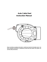
Installation Mounting Options
Mounting Adapter Kit for Replacing Series
500 Reels
A Mounting Adapter Kit is available for installing an XD
Series Hose Reel in the same location that a Series 500
Hose Reel was previously installed. Order Graco Kit No.
24A224. See FIG. 2 and page 39.
A = Original Series 500 holes in mounting surface.
B = Holes on the bottom of adapter bracket, predrilled to
match original Series 500 hole configuration (A).
C = Holes on the top of the adapter bracket, predrilled to
match new XD Series Hose Reel base.
All Mountings
NOTE: Reels perform best when arm allows hose to pull
straight off the spool as shown in FIG. 3.
FIG. 2
AB
C
mounting
XD base
surface
Adapter 24A224
ti13795
To reduce the risk of injury, be sure the mounting sur-
face is strong enough to support the reels, weight of
the lubricants and stress caused by hard pulls on the
service hoses. See Technical Data, page 41 for
weights of hose reel assemblies.
FIG. 3
ti13258
Panel Mount (HN) Models
HP, HS Models

Installation
10 313431L
NOTE: Always use all 4 large flat washers with 4 bolts to
mount the hose reel pedestal to any surface.
All Models
Select the reel bank mounting location.
• For high ceilings, suspend a suitable support
structure for the reels, so the hoses will be long
enough to reach your service area.
• A reel bank mounted in a one-lift service bay
should be at least 6-ft (1.9m) from the center
line of the lift (FIG. 6).
• In a one-lift bay, mount the reel bank at least 6
feet (1.9 m) from the center line of the lift. In a
two-lift bay, mount the bank equal distance
between the lifts.
• A bank of all motor oil reels should be mounted
about 5 ft (1.5m) from the center of the lift,
toward the front of the lift rails (FIG. 6).
HP or HS Models Only
1. Determine the desired position of the roller support
arm (a) (FIG. 4).
• The hose reel is factory-assembled and shipped
with the roller support arm (a) in position AA
(HP Models) or EE (HS Models) (FIG. 4). If that
position is desired, skip step 2.
2. To reposition roller support arm to any other position
than the Ship Position (AA or EE):
• HP Model Reels
a. Secure spool against pedestal with C-Clamp.
b. Remove 4 nuts (b) and rotate arm to desired
position, BB, CC, DD, EE, or FF.
c. Check pawl to make sure it is not wedged. See
FIG. 5.
• HS Model Reels
a. Secure spool against pedestal with C-Clamp.
b. Remove 8 nuts (b) and 2 bolts (c) to rotate
arm to desired position, AA, BB, CC, DD, or
FF.
c. Check pawl to make sure it is not wedged. See
FIG. 5.
FIG. 4
ti12199a
a
CC
BB
b
*HP Models Shipping Position
DD
EE
FF
AA*
**HS Models Shipping Position
a
**EE
FF
DD
AA
BB
CC
b
ti13394
c

Installation
313431L 11
Overhead Installations
HS Models Only
1. Reposition guide arm to position AA. See Step 2 for
HS Model Reels (above).
2. Position the hose reel so the pedestal is facing up.
3. Using the lift truck, raise the reel as close to the
mounting location as possible.
4. Bolt hose reel to its mounting. Be sure it is secure
before lowering the lift truck.
5. Connect inlet supply line to inlet hose of the reel.
See Hose Installation, page 17.
NOTE:
• None of the hose reels listed in this manual come
with a Hose Inlet Kit.
6. Flush system.
To avoid contaminating the fluid with line-scale,
chips or other installation debris, before installing
meter or dispense valve to end of hose, flush the
equipment with a compatible solvent such as Stod-
dard solvent or mineral spirits.
a. Secure the end of the hose in a waste bucket.
b. Blow out entire lubricant supply line with air.
To reduce the risk of injury, when you are mounting a
hose reel overhead, always use a lift truck.
FIG. 5
Incorrect
Correct
FIG. 6
2
3
1
5 ft (1.5m) minimum for motor oil
1
6 ft (1.9m) minimum for 1 lift
2
Center between two lifts
3
ti13351

Installation
12 313431L
c. Pump solvent through line until fluid runs clear
and is debris free.
d. Pump lubricant through line until all solvent is
flushed out.
7. For enclosed channel installations, continue with
instructions on page 21. For all other installations,
continue Step 8.
8. Position hose stop so hose extends far enough for
all operators to reach dispensing valve and tighten
nuts to securely hold hose stop in place.
9. Install meter or dispense valve to end of hose follow-
ing instructions provided with the dispense equip-
ment. (NOTE: If installing an enclosure around hose
reel, install the enclosure before installing dispense
valve or meter to hose end.)
10. Adjust spring tension, page 19.

Installation
313431L 13
Other Mounting Options
Ceiling Mounting Without an I-Beam - Open Channel (All Models)
• For HP Model Reels Order Mounting Kit: 24A934, 24A935, 24A936, 24A937, 24A938 or 24A939. For HS or HN
Model Reels Order Mounting Kit: 24A219, 24A220, 24A221, 24A222.
• See page 45 for mounting channel dimensions.
1. Install the mounting channel (105) and (HP Models)
base plate (104) as shown in FIG. 7.
HP Models: Open Channel Mounting Kits HS Models: Mounting Kits
FN Description
24A934
1 Reel
24A935
2 Reels
24A936
3 Reels
24A937
4 Reels
24A938
5 Reels
24A939
6 Reels
24A219
1 Reel
24A220
2 Reels
24A221
3 Reels
24A222
6 Reels
101PLATE, hold down123456
102 SCREW, 3/8” - 16 x
5/8” 5 1015202530 4 8 1224
103WASHER, lock, 3/8”5 1015202530 4 8 1224
104 BASE, reel 123456
105 BASE, reel, channel 1111111111
FIG. 7
105
103
102
101
104
ti13185

Installation
14 313431L
Ceiling Mounting Directly to an I-Beam - HP
Models Only
1. Using the template (B), provided, drill holes in the
I-Beam (C) (FIG. 8).
2. Bolt reel to I-Beam.
3. If you are installing permanent supply lines, drill 1.5
in. (38 mm) diameter holes through the ceiling
toward the inlet side of the reels.
4. Continue installation following steps 5 - 10 of Over-
head Installations instructions, beginning on page
11.
Ceiling Mounting to I-Beam without Drilling
Holes - All models
(Order Mounting Bracket Kit: 204741 for open or
enclosed reels.)
NOTE: For mounting 1-3 reels, two kits are required. For
mounting 4-6 reels, three kits are required.
1. Secure mounting brackets (D) to the channel. Use
two mounting brackets for each 1- to 3 capacity
mounting channel (103). (Use 3 brackets for 4-6 reel
channels.)
2. Position the adjustable clamps (206) of the mount-
ing brackets over the I-Beam (A), and tighten them
securely (FIG. 9).
3. HP Model Reels only (FIG. 7, page 13): Slide hose
reel onto the base plate (104) and install the
hold-down plate (101), washer (103) and capscrew
(102). Tighten the screw firmly.
NOTE: For enclosed reels, use the Enclosure Kit Base
Plate (Part No. 302, page 21).
4. If you are installing permanent supply lines, drill 1.5
in. (38 mm) diameter holes through the ceiling
toward the inlet side of the reels.
FIG. 8
A
B
C
ti13186
FN Description Qty
201 WASHER, lock, 1/2” 2
202 SCREW, 1/2” - 13 x 1” 2
203 SCREW, 1/2” - 13 x 1-3/4” 2
204 NUT 1/2” - 13 2
205 NUT, spring clamp (not
shown) 2
206 CLAMP, beam 2
207 CHANNEL, unistrut 1

Installation
313431L 15
5. Connect inlet supply line to inlet hose of the reel.
See Hose Installation, page 17.
NOTE:
• The hose reels listed in this manual do not come
with a Hose Inlet Kit.
6. Flush system.
To avoid contaminating the fluid with line-scale,
chips or other installation debris, before installing
meter or dispense valve to end of hose, flush the
equipment with a compatible solvent such as Stod-
dard solvent or mineral spirits.
a. Secure the end of the hose in a waste bucket.
b. Blow out entire lubricant supply line with air.
c. Pump solvent through line until fluid runs clear
and is debris free.
d. Pump lubricant through line until all solvent is
flushed out.
7. For enclosed channel installations, continue with
instructions on page 21. For all other installations,
continue Step 8.
8. Position hose stop so hose extends far enough for
all operators to reach dispensing valve and tighten
nuts to securely hold hose stop in place.
9. Install meter or dispense valve to end of hose follow-
ing instructions provided with the dispense equip-
ment. (NOTE: If installing an enclosure around hose
reel, install the enclosure before installing dispense
valve or meter to hose end.)
10. Adjust spring tension, page 19.
FIG. 9
A
D
ti13187
207
206 203
201 / 202 / 204
205
103
206
D
203
204
201
202
ti13188

Installation
16 313431L
Wall Mounting
(For HP Model Reels Order Mounting Kit: 24A934, 24A935, 24A936, 24A937, 24A938 or 24A939.
For HS or HN Model Reels Order Mounting Kit: 24A219, 24A220, 24A221, 24A222.)
1. Adjust guide arm to desired position, FIG. 4, page
10.
2. Select the reel bank mounting location. Mount the
reel to a wall, using the provided template (B) for
laying out the holes you drill.
You can mount the base plate (104) to the wall for
easier installation and removal of the hose reel for
servicing (FIG. 10).
3. Slide hose reel onto the base plate (104) and install
the hold-down plate (101), washer (103) and cap-
screw (102). Tighten the screw firmly (FIG. 10).
4. Connect inlet supply line to inlet hose of the reel.
See Hose Installation, page 17.
NOTE:
• The hose reels listed in this manual do not come
with a Hose Inlet Kit.
5. Flush system.
To avoid contaminating the fluid with line-scale,
chips or other installation debris, before installing
meter or dispense valve to end of hose, flush the
equipment with a compatible solvent such as Stod-
dard solvent or mineral spirits.
a. Secure the end of the hose in a waste bucket.
b. Blow out entire lubricant supply line with air.
c. Pump solvent through line until fluid runs clear
and is debris free.
d. Pump lubricant through line until all solvent is
flushed out.
6. Position hose stop so hose extends far enough for
all operators to reach dispensing valve.
7. Insert screws through hose stop and tighten nuts to
securely hold hose stop in place.
8. Install meter or dispense valve to end of hose follow-
ing instructions provided with the dispense equip-
ment.
NOTE: If installing an enclosure around hose reel,
install the enclosure before installing dispense valve
or meter to hose end.
9. Adjust spring tension, page 19.
HP Models: Open Channel Mounting Kits HS / HN Models: Mounting Kits
FN Description
24A934
1 Reel
24A935
2 Reels
24A936
3 Reels
24A937
4 Reels
24A938
5 Reels
24A939
6 Reels
24A219
1 Reel
24A220
2 Reels
24A221
3 Reels
24A222
4 Reels
101PLATE, hold down123456
102 SCREW, 3/8” x 16 x
5/8” 5 1015202530 4 8 1224
103 WASHER, lock,3/8” 5 10 15 20 25 30 4 8 12 24
104 BASE, reel 123456
105 BASE, reel channel 1111111111
FIG. 10
ti13189
101 104
B
103
102

Installation
313431L 17
Hose Installation
Installing a Hose on a Bare Reel
1. Locate length of your hose in table below. Note how
many times you must turn the spring to properly pre-
set spring tension.
2. Before you install hose, attach a C-Clamp (D) to reel
flange to help prevent the reel from unintentionally
becoming unlatched and spinning freely. (FIG. 11).
3. Place a piece of tape on the side of the reel flange
to use as a visual reference to help you count the
number of reel turns.
4. Wearing heavy gloves, firmly grab the outside edge
of the reel flange with both hands. Wind the reel the
proper number of turns (See reference table follow-
ing Step 1), rotating it in the direction shown in FIG.
11.
• Stop only at latching locations.
• Stop reel where there is access to hose swivel
(A) (FIG. 12) and where reel is securely latched.
5. Uncoil and extend hose.
6. Install hose stop (C) to end of hose. If hose has a
warning tag (F), hose stop should be installed on
the same end of the hose as the warning tag.
Hose Length No. of Reel Turns
35 ft (10.7 m) 17
50 ft. (15.2 m) 21
65 ft. (19.8 m) 23
Never allow the reel to spin freely. Doing so causes the
hose reel to spin out of control, which could cause serious
injury if you are hit by the hose or other moving parts
Always wear heavy gloves when you adjust spring tension
to protect your hands from being cut on hose reel.
FIG. 11
D
B
ti13191

Installation
18 313431L
7. Run the end of hose (B), through the hose guide (G)
and then the hole (E) in reel (FIG. 12).
8. For air/water or oil reel, attach hose end (B) to
hose reel swivel (A). Then carefully remove
C-Clamp (D) (FIG. 11).
9. For grease reel, insert hose end (B) through
bracket (H). Attach hose end (B) to strain relief hose
(J).
10. Pull hose hard enough to release the latch, and
slowly allow the hose to retract.
11. Flush system.
To avoid contaminating the fluid with line-scale,
chips or other installation debris, before installing
meter or dispense valve to end of hose, flush the
equipment with a compatible solvent such as Stod-
dard solvent or mineral spirits.
a. Secure the end of the hose in a waste bucket.
b. Blow out entire lubricant supply line with air.
c. Pump solvent through line until fluid runs clear
and is debris free.
d. Pump lubricant through line until all solvent is
flushed out.
12. Position hose stop so hose extends far enough for
all operators to reach dispensing valve.
13. Insert screws through hose stop and tighten nuts to
securely hold hose stop in place.
14. Install meter or dispense valve to end of hose follow-
ing instructions provided with the dispense equip-
ment. (NOTE: If installing an enclosure around hose
reel, install the enclosure before installing dispense
valve or meter to hose end.)
15. Adjust spring tension, page 19.
FIG. 12
A
B
C
E
F
G
A
B
C
E
F
G
Grease reel
ti13190-2
Air/Water or Oil reel
JH
ti13190
ti13190-3
NOTICE
Do not bypass mounting bracket H. Failure to attach
the hose through mounting bracket H can cause
decreased retraction performance.

Installation
313431L 19
Increasing and Decreasing Spring Tension
Single Pedestal HP Model Hose Reels
Increasing Spring Tension
1. Pull out hose, 1 to 2 turns and engage latch.
2. Pull hose back through hose rollers.
3. Wrap a loop of hose onto the reel flange.
4. Check the spring tension; the hose must pull out
fully and retract fully. Wrap more loops, one at a
time around the reel flange until the spring has the
desired tension.
NOTE: Do not put so many loops onto the reel that the
spring winds up tightly before the hose is fully extended.
Decreasing Spring Tension
Remove loops to decrease tension.
• The hose reel spring is not a serviceable part. Do
not attempt to replace or service the hose reel
spring.
• The spring is always under great tension and could
be propelled with enough force to cause serious
injury.
• Never allow reel to spin freely. Doing so causes the
hose reel to spin out of control, which could cause
serious injury if you are hit by the hose valve or
other moving parts.
• Reel must be bolted securely in place when mak-
ing adjustments.

Installation
20 313431L
Dual Pedestal HS or HN Model Hose Reels
If hose is not retracting sufficiently or is wound too tight,
the tension can be increased or decreased using one of
the following procedures:
Increasing Spring Tension
(spring is too loose, hose does not retract completely or
retraction is sluggish)
1. Loosen screw (A) 3-5 turns. Do not completely
remove it.
2. Use a hex wrench to loosen, the two screws (B). Do
not completely remove them.
3. Insert a 3/8” square drive breaker bar in opening (C)
on the spring adjustment plate (D).
4. While holding the breaker bar securely, completely
remove the two screws (B).
5. Firmly grasp the breaker bar with both hands and
turn it clockwise one turn at a time to increase
(tighten) spring tension.
6. Replace and partially tighten one screw. You can
now remove the breaker bar. Pull out a section of
hose and allow it to retract to test the tension adjust-
ment.
7. If additional tension is required, insert the breaker
bar in the bracket again and remove screw. Then
repeat steps 5 - 6.
8. When you are satisfied with the new setting, tighten
screws A and B.
Decreasing Spring Tension
(spring is too tight, hose retracts too fast)
1. Loosen screw (A) 3-5 turns. Do not completely
remove it.
2. Use a hex wrench to loosen, the two screws (B). Do
not completely remove them.
3. Insert a 3/8” square drive breaker bar in opening (C)
on the spring adjustment plate (D).
4. While holding the breaker bar securely, completely
remove the two screws (B).
5. Firmly grasp the breaker bar with both hands and
turn it counter-clockwise one turn at a time to
decrease (loosen) spring tension.
6. Replace and partially tighten one screw. You can
now remove the breaker bar. Pull out a section of
hose and allow it to retract to test the tension adjust-
ment.
7. If additional adjustment is required, insert the
breaker bar in the bracket again and remove screw.
Then repeat steps 5 and 6.
8. When you are satisfied with the new setting, tighten
screws A and B.
FIG. 13
• Never allow the reel to spin freely. Doing so causes
the reel to spin out of control, which could cause
serious injury if you are hit by a tool or the hose.
• Reel must be bolted securely in place when mak-
ing adjustments.
ti12201
A
B
C
D
/