Page is loading ...

Operating instructions for
Pressure sensor, PCB+ type, three wires
Description
Pressure sensors of the PCB+ type are used to measure very small pressures (relative and differential ones). The
measured pressure is sensed by a semiconductor strain-gauge sensor or a ceramic capacitive sensor. The sensors
are designed for gases. In case of a semiconductor sensor, gases have to be non-aggressive and dry. The sensors
are adjusted at the factory. The sensors are not manufactured in the EX design.
Selected technical parameters:
Pressure ranges: 0.6 kPa to 100 kPa
Accuracy: 0.5% (1%) of range according to range and type of used sensor
Supply voltage range: 19 to 31 VDC or 230 V / 50Hz (optional)
Max. power consumption: 1.2 VA, replaceable internal fuse T32 mA
Influence of supply voltage on accuracy: max 0.05% of range / 10 V
Output signal: 0 to 10 V three-wire load min. 1 MΩ (standard)
0 (4) to 20 mA three-wire load max. 500 Ω
Influence of load resistance: max. 0.05% / 500 Ω.
Power polarity reversal resistance and short circuit resistance at the output: permanent.
semicond. sensor capacit. sensor
Operating range of temperatures: -20°C to 70°C 0°C to 60°C (DC power supply 119 to 31 V)
-20°C to 50°C 0°C to 50°C (AC power supply 230 V / 50 Hz)
Compensated range of temperatures: 0°C to 60°C 10°C to 40°C
Influence of temperature in the compensated range of temperatures
a. zero: 0.1 … 1.8% / 10°C depends on the pressure range and the sensor type
b. range: 0.1 … 1.8% / 10°C depends on the pressure range and the sensor type
Switching of limits, only for versions with display:
a. the number of limits: 1 to 2
b. output: 1 switching contact, load capacity 5A / 230V AC
Material of the box: ABS
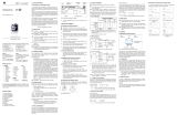
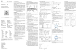
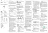
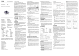
Fig. 1 Mechanical dimensions: Fig. 2: Location of terminal blocks on the printed circuit board
(view with the removed cover of the sensor in a vertical position)
Power supply
230V / 50Hz:
L: 1
N: 2
19 … 31 VDC:
+U: 2
0: 4
Output + : 3
Output -: 4
Relay contacts: 6
S1
5
7
9
S2
8
10

Mechanical assembly
The sensor should be fixed using four clips on the housing. The sensor cannot be placed in an immediate
proximity of interference sources (transformers, transmitters, motors) and heat sources. Shocks or vibrations at
the installation site can cause an error. Correctly, the sensor has to be mounted in a vertical position (pressure
inlets oriented down). In this position, the sensors are adjusted at the factory. This position prevents
a condensate from the penetration into the sensor. WARNING! Prior to mounting, make sure that there is no
liquid in the threaded insert of the closed valve. Remaining liquid has to be removed properly. The sensor
cannot be mounted if there is liquid in the thread.
Connection of the measured pressure (using 1/4“ hose)
The higher pressure is connected to the "+" inlet, the lower pressure to the "-" inlet. In case of a risk of water
vapor condensation, condensation loops have to be created on the hoses. The version of the sensor for
measuring the relative pressure includes only a single inlet. Blowing into pressure inlets is not allowed. Sensors
to be used up to 100 mbar can be damaged or destroyed by air pressure from lungs.
Commissioning
Remove the cover of housing. Connect electrical power using the connection terminals (see Fig. 2). Thread the
outlets through the cable gland. The sensor is equipped with the polarity reversal protection.
! The version with 230 V / 50 Hz power supply may only be connected by an authorized person according
to the notice No. 50/78 Coll. §6 and above!
The 230 V / 50 Hz power supply has to be connected using a cable VM05VV-F 2 x 0.75mm
2
or equivalent. The
same type of the cable or the equivalent one with the cross-section of 0.75 mm
2
has to be used also for
switching outputs when 230 V / 50 Hz is switched. The power supply has to be connected through a 6A circuit
breaker serving for the disconnection.
Outlets have to be threaded through cable glands. For 230V / 50Hz power supply, a separate cable and
a separate cable gland (the first one from the right) have to be used. A separate cable gland (the first one from
the left) has to be also be used for outputs of switching levels if 230 VAC is switched.
The third cable gland (the bottom center one) is used for the output signal. After removing the outer insulation
of the cable, separate wires have to be threaded through the appropriate catch loops froward to the terminal
board. This is unconditionally true for all the wires of the version with 230 V / 50 Hz supply or even where
only the switching outputs are connected to 230 V / 50 Hz.
Display
The display shows data in pressure units or according to user's request. The user can adjust the range of the
display.
After switching on, the output signal can be measured. When changing the output signal, two circumstances
have to be taken into account.
1) The starting time is 5 minutes. After that time, the output signal has to be stable at the zero differential
pressure and the constant temperature.
2) For measuring ranges below 100 mbar, the shift of zero occurs due to the change of the sensor position.
After passing the starting time, the error can be reset by the zero-setting potentiometer RP1.
Settings
In general
When designing the display, a simple operation and a customer control were primarily emphasized. Particular
functions are set by two buttons on the front side via the system of menus. The settings are permanently saved
in the Flash-EPROM memory and can be password-protected against an unauthorized manipulation. The
indicator of measured values (or individual menus) comprises a four-digit seven-segment display with the
height of digits being 7.62 mm.

Location of control elements and the display:
Unit The unit of the quantity to be displayed has to be selected when ordering the display. Later, the unit can
be changed using the supplied self-adhesive stickers with the units.
Displaying status of the switch
A LED diode is used to display the status of the switch. The diode shines if the switching point is
reached and the switching output is switched on.
Displaying measured values and adjusting display functions
A four-digit display is used to display the measured value and to adjust functions. The measured value is
displayed in units defined by the user and depends on the range and adjusted settings.
Control elements for setting the functions
For the control, two buttons located under a foil can be used. The user moves forward in the menu or
increases the values on the display by the "▲" button . The "▼" button is used to decrease the values
and to move backward in the menu.
The menu system is closed. By scrolling the particular menu items forward and backward, the desired
set-point can be achieved.
If the buttons are pressed for a longer time (> 5 seconds), the rate of change of the value on the display
is gradually increased in two steps.
By simultaneous pressing of both the buttons,
- the display mode is changed to the configuration mode
- the adjusted value is saved
- the display is returned to the display mode
ATTENTION: Change of adjusted parameters (switching point, hysteresis, etc.) becomes effective after
returning to the display mode.
Calibration of the lower limit of the display using a reference
During the lifetime of the pressure sensor, the lower limit may shift. The lower limit of the display is
calibrated for the value of 0 mA or 4 mA (or 0 V in the version 0 ... 10 V). Therefore, the value on the
display can differ from the adjusted beginning of the measuring range.
For the calibration, a pressure reference has to be used.
The PAof in the menu should be selected. Both the buttons should simultaneously be pressed.
Control diode of
the switch 1
Unit Control diode of
the switch 2
Display
Menu down Menu up

• The number 0247 should be entered to select the special function.
• Both the buttons should be pressed simultaneously again. The following value appears on the
display:
• Now, the pressure sensor has to be pressurized via the pressure reference. The pressure has to
correspond to the lower limit of the measuring range.
• When both the buttons are pressed again, the output signal of the sensor is saved as the lower limit.
From this moment, the entry adjusted as the beginning of the measuring range appears on the
display, although the sensor signal is shifted.
ATTENTION: Please note that the output signal of the converter remains unaffected by this change.
Calibration of the upper limit of the display using a reference
During the lifetime of the pressure sensor, the upper limit may shift. The upper limit of the display is
calibrated for the value of 20.000 mA (or 10 V in the version 0 ... 10 V). Therefore, the value on the
display can differ from the adjusted end of the measuring range.
• The PAof menu should be selected.
• Both the buttons should simultaneously be pressed.
• The number 0238 should be entered to select the special function.
• Both the buttons should be pressed simultaneously again. The following value appears on the
display:
• Now, the pressure sensor has to be pressurized via the pressure reference. The pressure has to
correspond to the upper limit of the measuring range.
• When both the buttons are pressed again, the output signal of the sensor is saved as the upper limit.
From this moment, the entry adjusted as the end of the measuring range appears on the display,
although the sensor signal is shifted.
ATTENTION: Please note that the output signal of the converter remains unaffected by this change.
Return to factory calibration
The control system of the display is equipped with the ability to restore the factory calibration. That
way, all the calibrations performed by the user are canceled.
• To load the factory adjustment, the PAof in menu should be selected.
• Then, both the buttons should be pressed.
• The number 0729 should be entered to select the special function.
• Both the buttons should be pressed simultaneously again. The following value appears on the
display.
• If both the buttons are simultaneously pressed again, the factory adjustment is activated again.
Restrictions on entering a password
ATTENTION: Due to special functions, the numbers 0247, 0238, 0729 cannot be used for the password.

Structure of the menu
Adjustment of password protection - password active
If the password is activated, the user is asked after pressing both the
control buttons for the password to make settings in the menu system.
Adjustment of the password protection - password inactive
If not activate, the password can be activated by pressing both the
buttons simultaneously and entering a predetermined secret number. In
factory setting, 5 is the corresponding number. To change this number,
both the buttons should be pressed simultaneously. Then, the number
0835 should be adjusted. Afterwards, both the buttons should be
pressed simultaneously again, and the password within 0 and 9999
should be adjusted by buttons. The number is confirmed by pressing
both the buttons simultaneously. That way, the new password is
adjusted. To activate password protection, both the buttons should be
simultaneously pressed and the password can be adjusted. Then, both
the buttons should be pressed simultaneously again.
Adjustment of decimal point
After pressing of both the buttons simultaneously, position of the
decimal point can be adjusted. The desired position can be selected
using "▲" or "▼" buttons. Pressing both the buttons simultaneously,
the settings are closed.

Adjustment of zero
Pressing both the buttons simultaneously, the lower limit of the range
can be adjusted. The adjusted value appears on the display when the
output signal of the sensor is 4 mA / 0 V. Pressing both the buttons
simultaneously, the settings are saved.
Adjustment of the upper limit of the range
Pressing both the buttons simultaneously, the upper limit of the range
can be adjusted. The adjusted value appears on the display when the
output signal of the sensor is 20 mA / 10 V. Pressing both the buttons
simultaneously, the settings are saved.
Adjustment of attenuation (filter)
After pressing both the buttons simultaneously, the time interval of the
attenuation can be adjusted. The range of the adjustment is from 0.3 to
30 seconds. Pressing both the buttons simultaneously, the settings are
saved.
Activation of report about exceeding the range
After pressing both the buttons simultaneously, the report about
exceeding the lower or upper limit of the range can be activated. The
status "ON" or "OFF" can be selected. Pressing both the buttons
simultaneously, the settings are saved.
Adjustment of the closing limit of the switch 1
After pressing both buttons simultaneously, the closing value of the
switch 1 can be adjusted. Pressing both the buttons simultaneously, the
settings are closed.
Adjustment of the opening limit of the switch 1
After pressing both the buttons simultaneously, the opening of the
switch 1 can be adjusted. Pressing both the buttons simultaneously, the
settings are saved.
Adjustment of the closing limit of the switch 2
After pressing both buttons simultaneously, the closing value of the
switch 1 can be adjusted. Pressing both the buttons simultaneously, the
settings are closed.
Adjustment of the opening limit of the switch 2
After pressing both the buttons simultaneously, the opening of the
switch 1 can be adjusted. Pressing both the buttons simultaneously, the
settings are saved.
Adjustment of the comparator mode and the hysteresis of the switch 1
After pressing both the buttons simultaneously, the hysteresis mode
and the comparator mode of the switch 1 can be switched. The
difference between both the modes of operation is given by the
illustration given in the note. Pressing both the buttons simultaneously,
the settings are saved.
Adjustment of the comparator mode and the hysteresis of the switch 2
After pressing both the buttons simultaneously, the hysteresis mode
and the comparator mode of the switch 1 can be switched. The
difference between both the modes of operation is given by the
illustration given in the note. Pressing both the buttons simultaneously,
the settings are saved.

Adjustment of the closing delay of the switch 1
After pressing both the buttons simultaneously, we can adjust the
closing delay of the switch 1 after reaching the closing limit. The range
of the adjustment is from 0 to 100 seconds. Pressing both the buttons
simultaneously, the settings are saved.
Adjustment of the opening delay of the switch 1
After pressing both the buttons simultaneously, we can adjust the
opening delay of switch 1 after reaching the opening limit. The range
of adjustment is from 0 to 100 seconds. Pressing both the buttons
simultaneously, the settings are saved.
Adjustment of the closing delay of the switch 2
After pressing both the buttons simultaneously, we can adjust the
closing delay of the switch 1 after reaching the closing limit. The range
of the adjustment is from 0 to 100 seconds. Pressing both the buttons
simultaneously, the settings are saved.
Adjustment of the opening delay of the switch 2
After pressing both the buttons simultaneously, we can adjust the
opening delay of switch 1 after reaching the opening limit. The range
of adjustment is from 0 to 100 seconds. Pressing both the buttons
simultaneously, the settings are saved.
Maximum value - since version 6.00
After pressing both the buttons simultaneously, the maximum value
occurred during the measurement is shown on the display. If both the
buttons are within one-second interval pressed again, the saved value is
deleted. Please note that the value does not stay saved when the power
supply is interrupted (current loop).
Minimum value - since version 6.00
After pressing both the buttons simultaneously, the minimum value
occurred during the measurement is shown on the display. If both the
buttons are within one-second interval pressed again, the saved value is
deleted. Please note that the value does not stay saved when the power
supply is interrupted (current loop).
Frequency of value recovery on the display - since version 7.00
After pressing both the buttons simultaneously, we can adjust the
frequency of value recovery on the display. The range of adjustment is
from 0 ... 10 s. When adjusting 0 s, the function is not active. The
adjusted value does not affect the function of the switches. Pressing
both the buttons simultaneously, the settings are saved.

Note:
Certificate of quality and completeness
Type : …………………………………………………………
Serial number : …………………………………………………………
Power supply : …………………………………………………………
Range : …………………………………………………………
Pressure overload : …………………………………………………………
Accuracy : …………………………………………………………
Technical inspection of offset : …………………………………………………………
Technical inspection of range : …………………………………………………………
Display data : …………………………………………………………
Manufacture date : …………………………………………………………
Warranty period : …………………………………………………………
Signature : …………………………………………………………
SENSORS s.r.o.
•
Hradišťská 817
•
687 08 Buchlovice
•
Tel. 572 432 111
•
572 432 116
•
E-mail: sale@bdsensors.cz
PCB3 Rev. 2/07
Hysteresis
mode
0
1
Compare
mode
0
1
Pressu
re S1ON S1OF
0
max.
t [s]
→
/
