Page is loading ...

Providing sustainable energy solutions worldwide
178 083 26-3 P93783 2023-06-22
Installation- and maintenance instruction
STG 146i/2 J/K
LMV37
Jumo dTRON 316
MB-DLE 407
IP40
Translation of the original instructions.

2Bentone
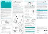
example Beispielexempel
352011030141
Designation
Type
Model
Serial no.
Motor supply
Main supply
MADE IN SWEDEN BY
LIGHT OIL 35-90kW 1,25-6,0 cSt 7-14bar
BF 1 KS 76-24
BF 1
BF 1 KS 76-24
1234567
1~230V 1,0A 50Hz IP 20
Man.Year 2019
Cap. Min-Max
3
?
1
-sv
1. Manualer på övriga språk
2. www.bentone.com\
nedladdning eller scanna
QR-koden.
3. Skriv in brännarens
artikelnummer som nns på
din typskylt (se bild) och välj
ditt språk.
Detaljerad ecodesign
information kan laddas ner
på: www.bentone.com/
ecodesign.
-en
1. Manuals in other languages
2. www.bentone.com\download
or scan QR-code.
3. Enter the burner`s article
number on your data plate (see
picture) and select language.
Detailed ecodesign information
can be downloaded at:
www.bentone.com/ecodesign.
-da
1. Manualer på andre sprog
2. www.bentone.com\
download eller scan
QR-koden.
3. Indtast brænderens
artikelnummer, der ndes
på typeskiltet (se billede), og
vælg dit sprog.
Detaljerede oplysninger om
ecodesign kan downloades
på: www.bentone.com/
ecodesign.
-fr
1. Manuels dans d’autres
langues
2. www.bentone.com\
download ou scannez le code
QR.
3. Saisir le numéro d’article
du brûleur sur votre plaque
signalétique (consultez
l’illustration) et sélectionnez
la langue.
Des informations détaillées
sur l’écodesign peuvent être
téléchargées à l’adresse:
www.bentone.com/
ecodesign.
-de
1. Gebrauchsanweisungen in
anderen Sprachen
2. www.bentone.com\download
oder scannen Sie den QR-Code.
3. Geben Sie die Artikelnummer
des Brenners auf Ihrem
Typenschild ein, (siehe Bild)
und wählen Sie die Sprache
aus.
Detaillierte Informationen zum
Ecodesign können unter
www.bentone.com/ecodesign
heruntergeladen werden.
2

3 Bentone
Table of contents
1. General Information ............................................................4
1.1 Delivery inspection........................................................................ 4
1.2 Safety ............................................................................................... 4
1.3 What to do if you smell gas ......................................................... 5
2. Technical data .......................................................................6
2.1 Dimensions STG 146i/2 ................................................................ 6
2.2 Capacity range ............................................................................... 7
2.3 Gas categories, approved gases ................................................ 7
2.4 Technicalspecication ................................................................. 7
2.5 Workingeld .................................................................................. 8
2.6 Setting for nozzle assembly and air damper ......................... 8
2.7 Components ................................................................................... 9
2.8 Skeleton diagrams, 1-stage burner ........................................11
3. Electric equipment ............................................................. 12
3.1 Safety system .............................................................................. 12
3.2 Components ................................................................................. 12
3.3 Wiring diagram ............................................................................ 13
4. Automatic control unit LMV37 .........................................14
4.1 System structure/function description ...................................14
4.2 General information ................................................................... 15
4.3 Technical Data Basic unit LMV37.4... .......................................15
4.4 Connection and internal diagram............................................20
5. Operation LMV37 ...............................................................22
5.1 LMV37 automatic control unit ..................................................22
5.2 List of phase displays ................................................................. 24
5.3 Automatic control unit levels .................................................... 25
5.4 Setting the automatic control unit ..........................................29
5.5 Backup and restore .................................................................... 41
5.6 Fault status message, display of errors and info .................45
5.7 Dispaly message of info ............................................................. 50
5.8 Resetting the automatic control unit ...................................... 51
5.9 Manual output ............................................................................. 52
6. Parameter list - LMV37 ......................................................54
7. Error code list - LMV37 ......................................................64
8. Controller JUMO dTRON 316 .............................................79
8.1 Preface...........................................................................................79
8.2 Scope of delivery ......................................................................... 79
8.3 Mounting ...................................................................................... 79
8.4 Electrical connection .................................................................. 80
8.5 Displays and keys ........................................................................ 81
8.6 Operation ......................................................................................82
8.7 Parameter level „PArA“ ..............................................................85
8.8 Congurationlevel„ConF“........................................................ 86
8.9 Autotuning .................................................................................... 89
8.10 Alarms ............................................................................................ 89
8.11 Factory settings Controller JUMO ............................................ 90
9. Installation ..........................................................................97
9.1 General instructions ................................................................... 97
9.2 Instructions .................................................................................. 97
9.3 Inspection and maintenance .................................................... 97
9.4 Preparation for assembly ......................................................... 97
9.5 Gas supply .................................................................................... 97
9.6 Electric connection ..................................................................... 97
10. Mounting ............................................................................98
10.1 Gas nozzle.....................................................................................99
10.3 Tightness control ......................................................................100
10.2 De-aerating .................................................................................100
10.4 Calculationofgasow ............................................................101
10.5 Calculate prepurge time, Industrial applications ..............102
11. Settings .............................................................................103
11.1 Air settings .................................................................................103
11.2 Nozzle adjustment ....................................................................103
11.3 Startup ......................................................................................... 104
11.4 Control of combustion ............................................................104
11.5 Settingtheairpressureswitch ..............................................105
11.6 Settingthegaspressureswitchmin/VPS ............................106
11.7 Settingthegaspressureswitchmax/
overloadprotectionswitch .....................................................107
12. Gas valve MultiBloc DLE 405 - 412..................................108
13. Service ...............................................................................111
13.1 Burner Service Schedule, Gas ................................................111
13.2 Component replacement intervals ........................................111
13.3 Combustion device ...................................................................112
13.4 Fanmotorandfanwheel ........................................................113
13.5 Air intake and suction cone ....................................................114
13.6 Replacement of electrical components ................................ 115
13.7 Vibrations .................................................................................... 116
13.8 Flame monitoring and ionisation current check ................117
13.9 Flame detector QRC .................................................................118
14. Handing over of the installation ....................................119
15. Troubleshooting ...............................................................120
16. Service- and inspection protocol ................................... 122

4Bentone
172 515 01-2 2021-10-05
1. General Information
The burner may only be used for its intended purpose in accordance with the
product’s technical data.
We reserve the right to make design changes and cannot be held liable for any
misprints or typographical errors.
Modifying the design or using accessories or components that have not been
approved by Enertech in writing is strictly prohibited.
This Installation and Maintenance manual:
• is to be regarded as part of the burner and must always be kept near
the installation site.
• must be read prior to installation.
• is intended for use by authorised personnel.
1.1 Delivery inspection
• Make sure everything is delivered and the goods have not been
damaged during transit. Transport damage should be reported to the
shipping company.
• If something is wrong with a delivery, report it to the supplier.
1.2 Safety
- before installation:
• Installation and work on the burner and associated system
components may only be carried out by persons who have undergone
relevant training.
• The product is packaged to prevent damage from occurring when
handled – Handle the product with care! Lifting equipment must be
used to lift larger packages.
• The products must be transported/stored on a level surface in a dry
environment, max. 80% relative humidity, no condensation.
Temperature -20 to +60 °C.
- installation:
• The burner must be installed in accordance with local regulations for
re safety, electrical safety, and fuel distribution.
• The premises must comply with local regulations pertaining to use of
the burner and must have adequate air supply.
• The installation site must be free of chemicals.
• Fire extinguisher with Class BE recommended.
• Make sure when installing the burner that there is enough space to
service the burner.
• The electrical installation must be professionally carried out in
accordance with current mains electricity regulations and in a
professional manner.
• Make sure that the burner is suitable for the application (see Technical
Data).
• All components must be installed without being bent, twisted or
subjected to mechanical or thermal forces that affect components.

5 Bentone
• Care must be taken by the installer to ensure that no electrical cables
or fuel lines are pinched or otherwise damaged during installation or
service.
• Sharp edges can occur on, for example: ame tube, fan wheel and air
damper.
• The gas outlet from the pressure regulator must be congured in
accordance with applicable regulations and lead to a safe area.
- before rst start:
• The burner must not be put into operation without proper safety and
protection devices.
• Permitted ambient temperature during operation -10 to +60 °C. Max.
80% relative humidity, no condensation.
• The surface temperature of the burner’s components may exceed
60 °C.
• Handle with caution – the burner has moving parts, and there is risk
of crushing injuries.
• Seal inspections must be performed during installation and servicing
to prevent leakage.
• Fitting and installation work has been completed and approved.
• Electrical installation has been correctly performed.
• Flue gas ducts and combustion air ducts are not blocked.
• All actuators and control and safety devices are in working order and
correctly set.
• If the boiler is equipped with an access hatch, this must be equipped
with a hatch opening switch connected to the burner’s safety system.
• When in operation, the burner’s noise level can exceed 85 dBA – use
hearing protection!
- Operation:
• Carry out all stipulated settings, service and inspection work within
the set time.
1.3 What to do if you smell gas
• Turn off the fuel supply.
• Turn off the device and remove the boiler from operation.
• Open windows and doors.
• Prevent open ames or sparking, e.g. do not turn lights on or off, do
not use any electrical appliances or mobile phones.
• Evacuate the building.
• Notify the installer or gas supplier of the problem so that it can be
rectied.

6Bentone
172 535 22-3
2. Technical data
The burner is intended for:
• Operation with boiler according to EN 303, EN 676 and EN 746-2.
Fuels:
• Natural gas H, E, L, LL.
• LPG Butane G30 and Propane G31.
2.1 Dimensions STG 146i/2
* Min. recommended distance to oor.
2.1.1 Measurements for connection to boiler
N
M
L
O
D
160303-540
A
F
E
øB øC
*K
G H
160303-541
J
I
L M N O
10.5 Ø 110 Ø 140-170 12.5
D E F G H I J *K
269 239 197 200 158 101 32 200
Length of
ame tube
Flame tube
measure A
Flame tube
measure B
Flame tube
measure C
145 122 ø104 ø89
245 222 ø104 ø89

7 Bentone
2.2 Capacity range
2.3 Gas categories, approved gases
Only dry gas is permitted for use.
STG 146i/2
G20 41 - 133 4.3 14.1 360 20 DLE 405
DLE 407
G25 41 - 133 5.0 16.4 360 20 DLE 405
DLE 407
G30 47 - 144 1.5 4.5 360 20 DLE 405
DLE 407
G31 47 - 144 1.9 5.9 360 20 DLE 405
DLE 407
160303-542-2
Capacity
kW
Gas quantity
at min. power
Nm3/h
Gas quantity at
max. power
Nm3/h
Max. connection
pressure
mbar
Min. connection
pressure
mbar
Gas valve
MultiBloc
Gas quantity and capacity vary according to grade of gas and connection pressure.
Category Country of destination Supply pressure
II2R3R AT, BE, BG, CH, CY, CZ, DE, DK, EE, ES, FI, FR, GB, GR, HR,
HU, IE, IS, IT, LT, LU, LV, MK, MT, NL, NO, PL, PT, RO, RS, SE,
SI, SK, TR
20 mbar
II2H3B/P AT, CH, CY, DK, FI, LT, RO, SE, SK 20 mbar
II2H3P GB, IE 20 mbar
II2L3B/P NL, RO 20 mbar
II2E3B/P PL 20 mbar
I2E(R)B BE 20 mbar
I3P BE 20 mbar
160302-302-4
Measurements according to EN 3746: 2010
Alt.1 The sound level of the burner can be reduced by equipping the burner
with silencer. Installation must be done so it does not prevent air supply
to the burner.
Alt.2 The burner’s noise level can be reduced by connecting the burner’s air
intake to the air duct that opens into an appropriate location. Installation
must be done so it does not prevent air supply to the burner.
2.4 Technical specication
STG 146i/2
Main supply 230V, 1~, 1.5A, 50Hz, IP40
Max fuse rating 10A
NOX-class 2
Noise level 78dBA

8Bentone
!Do not exceed working
eld.
2.5 Working eld
2.6 Setting for nozzle assembly and air damper
Basic settings should only be seen as setting values to get burner to start.
Once the burner has started and established ame, it is necessary to adjust the
settings so that they are adapted to the installation and the fuel used.
mbar
kW
G20, G25 - 41-133 kW
G30, G31 - 47-144 kW
-1,0
0,0
1,0
2,0
3,0
4,0
5,0
30 40 50 60 70 80 90 100 110 120 130 140 150
160302-961-2
0
4
8
12
16
20
24
28
32
40 50 60 70 80 90 100 110 120 130 140
160303-543
kW
Air settings
Nozzle assembly
Scale
Burner output

9 Bentone
2.7 Components
1. Fixing ange
2. Transformer
3. Connection, Gas valve
4. Gas pressure switch VPS
5. Gas valve (MultiBloc)
6. Pressure regulator
7. Filter
8. Ignition electrode
9. Ionization electrode
10. Brake plate
11. Motor
12. Fan wheel
13. Nozzle assembly adjustment
14. Air setting
160303-544
21 53 6
7
4
8
9
10
11 13 1412

10 Bentone
2.7.1 Components, Electrical cabinet
15. Electrical box
16. Gas pressure switch min.
17. Gas pressure switch max./
Overload protection switch
18. Flame tube
19. Air pressure switch
20. Main switch
21. Fuse
22. Connection block
23. Automatic control unit LMV
24. Display AZL
(automatic control unit)
25. Reset
26. Operating switch 0-I
27. Regulator RWF
160303-546
24 2523 26
20 22
19
21
160303-545
160303-547
15 16
18
1716

11 Bentone
172 515 04 2018-01-02
2.8 Skeleton diagrams, 1-stage burner
1 Ball valve
2 Filter
3 Pressure regulator
4 Pressure gauge with shut-off cock
5a Gas pressure switch, Min.
5b Gas pressure switch, Max.
6a Main valve
6b Safety valve
7 1) Leakage control
9 Air pressure switch
10 Burner control
Pos. 5b, 7: Components not required according to EN 676.
1) Required over 1200 kW according to EN 676.
3
6b
5b
10
6a
9
7
12
5a
4

12 Bentone
172 625 38-1
3. Electric equipment
3.1 Safety system
The safety system (safety switch for hatches, doors, water level, pressure,
temperature and other safety devices) must be installed in the safety
circuit in accordance with current regulations for the system. If these safety
requirements are met by other means, safety circuits must be bypassed.
This can differ between different systems in which the burner is installed,
see rules and regulations that apply.
The cables of the safety system must be separated so that the outgoing
signal is not placed in the same cable as the incoming signal.
3.2 Components
A1 Burner control
A2 Regulator
AL Alarm
F1 Fuse
F2 Fuse
B1 Ionization electrode
M1 Motor
PT100 Sensor
S1 Operating switch 0-I
S7 Main switch
S8 Air pressure switch
S9 Gas pressure switch, min
S10 Gas pressure switch, max
S17 Leakage control, VPS
T1 Ignition transformer
X1 Connection block
X20 Connection block
X56 Connection, display
Y1 Solenoid valve 1
Y2 Solenoid valve 2
!The installation of a safety
system is required to start
the burner.
!Mains connection and fuse
in accordance with local
regulations.

13 Bentone
3.3 Wiring diagram
Bk Black
Bn Brown
Bu Blue
Gn Green
Gn/Ye Green/Yellow
Gy Grey
Og Orange
Pk Pink
Rd Red
Vt Violet
Wh White
Ye Yellow
E106384

14 Bentone
4.1 System structure/function description
The LMV37.4... is a microprocessor-based burner management system with
matching system components for the control and supervision of forced draft
burners of medium to high capacity.
Integrated in the basic unit of the LMV37.4... are:
• Burner management system complete with valve proving system
• Electronic air-fuel ratio control system for a maximum of
2 SQM3... or SQN1... actuators
• Control of VSD air fan
• Modbus interface
Example: Modulating gas burner
The system components (display and operating unit, actuators) are connected
directly to the LMV37.4... basic unit. All safety-related digital inputs and outputs
of the system are monitored by a contact feedback network.
4. Automatic control unit LMV37
At the time of writing, of the parameters mentioned above, motor frequency
control and communication via modbus are not available on the burner models
described in this manual.
172 525 55
The LMV37 automatic control unit is a piece of control equipment that can be
used for many different types of burner.
In the following review of how this control equipment works and can be
adjusted, the description will focus on the type of burner covered by this
manual.

15 Bentone
4.2 General information
The burner management system is operated and parameterized via the
AZL2… display. The AZL2… with LCD and menu-driven operation facilitates
straightforward use and targeted diagnostics. When making diagnostics, the
display shows the operating states, the type of error and the point in time the
error occurred.
Passwords protect the different parameter levels of the burner against
unauthorized access. It is possible to select from different types of fuel trains
and make use of a wide choice of individual parameter settings (program
times, conguration of inputs / outputs, etc.), enabling the installer to make
optimum adaptations to the relevant application. A change of parameters
varies in levels of authorization, this manual will give info on those that might
be changed by the installer. The actuators are driven by stepper motors and
can be positioned with high resolution. Specic features and actuator settings
are dened by the LMV37.4... basic unit.
4.3 Technical Data Basic unit LMV37.4...
Mains voltage
LMV37.400A2 AC 230 V -15 % / +10 %
Mains frequency 50 / 60 Hz ±6 %
Safety class I, with parts according to II and III to
DIN EN 60730-1
Perm. mains primary fuse
(externally)
Max. 5 AT
Unit fuse F1 (internally) 6.3 AT (DIN EN 60127 2 / 5)
Mains supply: Input current depending
on the operating state of the unit
Under voltage
Safety shutdown from operating
position at mains voltage
LMV37.400A2 Approx. AC 186 V
Restart on rise in mains voltage
LMV37.400A2 Approx. AC 195 V

16 Bentone
M
t1
p
P
P
LP
Z
AL
V1
V2
5 s5 s 30 s
POC *)
X3-04 pin 1/2
X5-03 pin 1/4
X10-05
pin 2 / pin 3/4
X10-06 pin 1/2
X3-02 pin 1/2
X5-01 pin 2/3
X5-02 pin 2/3
X5-02 pin 2/3
X3-05 pin 1
X4-02 pin 2/3
X6-03 pin 2/3
X8-02 pin 1/3
X7-01 pin 2/3
X7-02 pin 2/3
X3-05 pin 2
P
P
X9-04 pin 2/3
X5-01 pin 2/3
R (ON)
Function / Inputs
Function / Outputs
RAST plug
pin number
RAST plug
pin number
Gas direct ignition «G», «G mod», «G mod pneu»
Legend to the sequence diagrams

17 Bentone
!Not all phases, times, indices, abbreviations and symbols
appear in the individual sequence diagrams or are needed
there!
Phase numbers
00 Lockout phase
02 Safety phase
10 Home run
12 Standby (stationary)
22 Fan motor (M) = ON, safety valve (SV) = ON
24 Air damper (LK) fuel valve (V) – position
30 Prepurging
36 Air damper (LK) ignition (Z) – position
38 Preignition ignition (Z) = ON
39 Test pressure switch-min (Pmin)
40 Fuel valve (V) = ON
42 Ignition (Z) = OFF
44 Interval 1 (t44)
50 Safety time 2 (TSA2)
52 Interval 2 (t52)
60 Operation 1 (stationary)
62 Operation 2 air damper (LK) low-re (KL) – position
70 Afterburn time (t13)
72 Air damper (LK) Rated load (NL) – position
74 Postpurge time (t8)
78 Postpurge time (t3)
80 Evacuation of test space
81 Atmospheric pressure test
82 Filling of test space
83 Gas pressure test
90 Gas shortage waiting time
Valve proving is performed depending on the parameter settings:
Simultaneously with the prepurge time and/or the afterburn time.

18 Bentone
Times
TSA1 1st safety time
t1 Prepurge time
t3 Postpurge time
t8 Postpurge time
t13 Afterburn time
t44 Interval 1
t52 Interval 2
Indices
1) Parameter: Short/long prepurge time for oil only
Short/long on time of oil pump – time
2) Only with valve proving during startup
3) Parameter: With/without alarm in the event of start prevention
4) If signal is faulty in the startup phase, phase 10 is next, otherwise
phase 70
5) Max. time safety phase, then lockout
6) Time from occurrence of start prevention to signaling
7) Only in case of valve proving during startup (valve proving via pressure
switch-min)
8) Only in case of startup without valve proving (valve proving via
pressure switch -min)
9) Inverse logic in case of valve proving via pressure switch-min
10) Parameter: Oil pressure min-input
1 = active from phase 38
2 = active from safety time
11) Only with fuel train Lo and 2 fuel valves
12) Parameter 223: Repetition limit value gas pressure switch-min in
connection with gas shortage program parameter
246 (phase 90)
13) Max. drop-in/response time for air pressure switch
14) Alternative to valve proving
15) Alternative to pressure switch-max (Pmax) or POC

19 Bentone
Abbreviations
AL Alarm
FS Flame signal
GM Fan motor contactor
LP Air pressure switch
M Fan motor
P LT Pressure switch for valve proving
Pmax Pressure switch-max
Pmin Pressure switch-min
POC Proof of closure
PV Pilot valve
R Temperature or pressure controller
SB Safety limiter
SK Safety loop
STB Safety limit thermostat
SV Safety valve
WM Water shortage
V1 Fuel valve 1
V2 Fuel valve 2
VP Combustion pressure switch
SA Actuator
SA-K Low-re position of actuator
SA-N Postpurge position of actuator
SA-R Home position of actuator
SA-V Rated load position of actuator
SA-Z Ignition load position of actuator
Z Ignition transformer
Permissible position range
In Standby mode: Actuator is allowed to travel within the
permissible position range, but is always
driven to the home position; must be in the
home position for phase changes
0°/10%
90°/100%
Position as supplied (0°)
Actuator fully open (90°)
Input/output signal 1 (ON)
Input/output signal 0 (OFF)
Input permissible signal 1 (ON) or 0 (OFF)
Symbols

20 Bentone
4.4 Connection and internal diagram
Shielding:
For shielding the cables on the VSD, refer to:
• Siemens SED2 VSD Commissioning Manual (G5192), chapters 4
and 7, or
• Danfoss Operation Manual VLT 6000 (MG60A703), chapter
Installation
X3-03X3-05
X3-04
X7-01
X75 X10-05 X3-02
X5-01 X9-04 X7-02
1 1 1 11 1 1 1 1
11
11
111
1
7546a14e/0913
+
Supply signal for end switch burner ange
Fan motor contactor
Alarm
Continuous fan operation
Extra valve SV
Ignition Z
Fuel valve V3 / pilot PV
Power supply phase conductor (L)
Power supply neutral conductor (N)
Protective earth (PE)
Supply signal for safety loop
Safety loop
Fuel valve V2
Wiring point for series valve
Fuel valve V1
Fuel indication oil / gas
Reset / manual locking
Supply for external load controller
external load controller Open / Stage 2
external load controller Open / Stage 3
external load controller (On / O)
Supply signal for air pressure switch (LP)
Air pressure switch (LP)
QRA....
Supply signal (L)
GND
QRB.../ QRC...signal voltage
Ionization probe (ION)
Protection earth (PE)
Supply for fuel meter
Input fuel meter
Pressure switch leakage test gas
(PLT) or GP (VPS)
Pressure switch-min-gas (Pmin) / -min-oil
Pressure switch-max-gas / -max-oil (Pmax) or POC
End switch burner ange (component of safety loop)
/