Page is loading ...

PROCESS AUTOMATION
PRODUCT INSTALLATION MANUAL
HART TERMINATION BOARD
HISHPSM/32/MM-01

With regard to the supply of products, the current issue of the following
document is applicable:
The General Terms of Delivery for Products and Services of the Electrical
Industry, published by the Central Association of the Electrical Industry
(Zentralverband Elektrotechnik und Elektroindustrie (ZVEI) e.V.) in its
most recent version as well as the supplementary clause: "Expanded
reservation of proprietorship."

3
Contents
1. Safety ............................................................................... 5
1.1 Validity ...................................................................................... 5
1.2 Safety-relevant symbols used .................................................. 5
1.2.1 Warning! ...........................................................................................5
1.2.2 Note! .................................................................................................. 5
1.3 Target group / personnel .......................................................... 5
1.4 Reference to further documentation ........................................ 5
1.5 Intended use ............................................................................ 6
1.6 Improper use ............................................................................ 6
1.7 Mounting/Installation ............................................................... 6
1.8 Operation, maintenance, repair ................................................ 7
1.9 Delivery, transport, disposal .................................................... 8
2. Disclaimer ....................................................................... 8
3. Copyright and trademark information .......................... 9
4. General information ...................................................... 10
4.1 Introduction ............................................................................ 10
4.1.1 System overview .............................................................................10
4.1.2 HART overview ................................................................................11
4.1.3 AMS software overview...................................................................11
4.2 Conditions of safe use ........................................................... 11
4.3 Product marking ..................................................................... 11
4.4 Technical specifications ......................................................... 12
4.5 Quality assurance ................................................................... 13
4.6 Certifications and compliance ............................................... 13
5. Installation ..................................................................... 14
5.1 Storage ................................................................................... 14
5.2 Unpacking and inspection ..................................................... 14
5.3 Environmental conditions ....................................................... 15
5.4 Intrinsic safety ........................................................................ 15
5.5 Mounting ................................................................................ 15
5.6 Cables .................................................................................... 15
5.7 Wiring ..................................................................................... 16
5.7.1 Power ..............................................................................................16
5.7.2 Grounding .......................................................................................17
5.7.3 RS-485 ............................................................................................18

4
5.7.4 Field connections ............................................................................20
5.7.5 Control connections ........................................................................ 22
6. Operation ....................................................................... 24
6.1 Start-up sequence ................................................................. 24
6.2 Configuration .......................................................................... 24
7. Troubleshooting ............................................................ 24
7.1 General ................................................................................... 24
8. Maintenance .................................................................. 24
9. Glossary ......................................................................... 25
10. Contact information ..................................................... 25

5
1. Safety
1.1 Validity
The chapter “Safety” is valid as instruction manual.
Specific processes and instructions in this document require special
precautions to guarantee the safety of the operating personnel.
1.2 Safety-relevant symbols used
This document contains information that you must read for your own
personal safety and to avoid property dam-age. Depending on the hazard
category, the warning signs are displayed in descending order as follows:
1.2.1 Warning!
This symbol indicates a possible fault or danger.
Non-observance may cause personal injury or serious property
damage.
1.2.2 Note!
This symbol brings important information to your attention.
1.3 Target group / personnel
Responsibility for planning, assembly, commissioning, operation,
maintenance, and dismounting lies with the system operator.
Mounting, installation, commissioning, operation, maintenance and
disassembly of any devices may only be carried out by trained, qualified
personnel. The instruction manual must be read and understood.
1.4 Reference to further documentation
Laws, standards, or directives applicable to the intended use must be
observed. In relation to hazardous areas, Directive 1999/92/EC must be
observed.
Laws, standards, or directives applicable to the intended use must be
observed.
The corresponding data sheets, declarations of conformity, EC-type-
examination certificates, certificates and control drawings if applicable
(see data sheet) are an integral part of this document. You can find this
information under www.pepperl-fuchs.com.
Due to constant revisions, documentation is subject to permanent change.
Please refer only to the most up-to-date version, which can be found under
www.pepperl-fuchs.com.

6
1.5 Intended use
The devices are only approved for appropriate and intended use. Ignoring
these instructions will void any warranty and absolve the manufacturer from
any liability.
The device must only be operated in the ambient temperature range specified.
The device must only be operated at the relative humidity (non-condensing)
specified.
The device must only be operated in the ambient temperature range and at
the relative humidity (non-condensing) specified.
If the device replaces a predecessor device, the documentation for the
verification of intrinsic safety must be adjusted.
1.6 Improper use
Protection of the operating personnel and the overall system is not ensured if
the product is not being used according to its intended purpose.
The equipment is not suitable for isolating signals in high current applications
unless this is noted separately in the corresponding datasheet.
The device is not used to separate intrinsically safe circuits from non-
intrinsically safe circuits.
1.7 Mounting/installation
Prior to mounting, installation, and commissioning of the device you should
make yourself familiar with the device and carefully read the instruction manual.
The device must not be installed at locations where corrosive vapors may be
present.
Do not install damaged or polluted devices.
Only use accessories specified by the manufacturer.
Place warning label “Warning – Refer to operating instructions!” visibly on the
housing.
Place warning label “Warning – Refer to operating instructions!” visibly on the
surrounding enclosure.
In order to ensure protection against electric shock, observe the following
instructions:
• Keep sucient separation distance between conductors, terminals,
housing, and environment.
• Insulate conductors, terminals, and housing from the environment.

7
1.8 Operation, maintenance, repair
Prior to using the device you should make yourself familiar with the device
and carefully read the instruction manual.
The devices must not be repaired, changed or manipulated.
Do not use damaged or polluted devices.
If there is a defect, the product must always be replaced with an original device.
If there is a defect, the product must be returned to the manufacturer,
Pepperl+Fuchs.
1.9 Delivery, transport, disposal
Check the packaging and contents for damage.
Check if you have received every item and if the items received are the ones
you ordered.
Keep the original packaging. Always store and transport the device in the
original packaging.
Store the device in a clean and dry environment. The permitted ambient
conditions (see data sheet) must be considered.
Disposing of devices, packaging material, and possibly contained batteries
must be in compliance with the applicable laws and guidelines of the
respective country.

8
2. Disclaimer
While the HART Interface Solution (HIS) Replacement Panels from
Pepperl+Fuchs, Inc. (“HIS Replacement Panels”) are designed to extract the
digital HART data from standard 4 ... 20 mA loops, the HIS Replacement
Panels may not provide all of the features, or duplicate all the functions, of
the panels they replaced, and Pepperl+Fuchs, Inc. makes no warranty or
representation (and specifically disclaims any express or implied warranty
or representation) that such HIS Replacement Panels are identical to, or
will provide all of the same features or duplicate all of the same functions
of, the panels they replace. The terms, conditions and limitations of any
product warranties covering HIS Replacement Panels may be obtained from
Pepperl+Fuchs, Inc.
The information set forth in this Manual is designed to assist the Purchaser
in the installation, operation and maintenance of an HIS Replacement Panel.
Such information should not be construed as a warranty or representation,
express or implied, regarding the HIS Replacement Panel or its use in, or
suitability for, a particular application, any such warranties or representations
being specifically disclaimed. The terms, conditions and limitations of any
product warranties covering HIS Replacement Panels may be obtained
from Pepperl+Fuchs, Inc. Pepperl+Fuchs, Inc. reserves the right to modify
or improve the designs, specifications, features and/or functions of HIS
Replacement Panels at any time without notice.

9
3. Copyright and trademark information
This manual is copyright of Pepperl+Fuchs with all rights reserved. This
manual may not be copied, in whole or in part, without the written consent
of Pepperl+Fuchs. Pepperl+Fuchs reserves the right to make changes to this
manual without notice.
Model Listing
Model Channels/function
HISHPSM/32/MM-01 32 I/O
To avoid damage, failure, or improper operation, read this manual
carefully before installing and operating the equipment.

10
4. General information
4.1 Introduction
This manual provides guidance for the installation, operation, and
maintenance of your Pepperl+Fuchs termination board, for use with the
HiDMUX2700. The solution is designed for easy multiplexer integration with
any control system.
HISHPSM/32/MM-01 Generic point-to-point wiring. Can be connected
to any control system
The HiDMUX2700 multiplexer will be referred to in this manual as
“MUX 2700.” For setup and specific details on operating the MUX 2700, see
the manual, datasheets, and other documentation for this product.
The HISHPSM/32/MM-01 will be referred to as “HPSM.” The combined
solution of a MUX 2700 and an HPSM will be referred to as a “HART interface
solution” or “HIS.”
4.1.1 System overview
Your HART interface solution interfaces up to 32 field-located HART devices.
The MUX 2700 is a HART signal multiplexer unit that allows access to HART
communications on existing 4 ... 20 mA wiring. It acts as a gateway device,
routing communications between the maintenance workstation PC and
the HART devices. The MUX 2700 uses Manchester encoding of the HART
protocol for the RS-485 link to the maintenance workstation PC. To link to
each of the HART devices, the MUX 2700 communicates using Bell 202
frequency-shift keying (FSK). It interrogates each HART device, retrieves
device information, and stores it in an internal database. This information
is available to the maintenance workstation software. In this way, the MUX
2700 gives the user access to each HART device as if connected directly at
the device itself. A maintenance workstation PC can use this information for
configuration, maintenance, calibration, diagnostics, and data access.
The termination board design allows the DCS and field device wiring to be
brought together with the MUX to complete the system. Various HPSM board
designs allow interface with dierent I/O cards and may include configurable
options such as fused or filtered signal lines, current to voltage conversion,
and loop or device powered instruments. HART Interface Solutions are
supplied by Pepperl+Fuchs in several models in order to allow simple and
reliable connection between SMART devices and various DCS systems.

11
4.1.2 HART overview
HART is an acronym for “highway addressable remote transducer.” The
HART protocol makes use of the Bell 202 FSK standard to superimpose
digital signals at a low level on top of the 4 ... 20 mA signal. This enables
two-way communication and makes it possible for additional information
beyond just the normal process variable to be communicated to/from a
SMART field instrument. The HART protocol allows a host application
(master) to receive two or more digital updates per second from a field
device. Because the digital FSK signal is phase continuous, there is no
interference with the 4 ... 20 mA signal.
4.1.3 Asset Management Solutions (AMS) Software Overview
AMS software provides an easy-to-use means for integrating various device
management software packages into a unified system. AMS operates under
the Microsoft® Windows® format. It combines the various device (or asset)
management tasks into an application with a common look-and-feel and
centralized data storage.
AMS provides access to functionality available via the HART communications
protocol for any HART device whose Device Description (DD) is registered
with the HART Communication Foundation.
For more information on installation of AMS software, consult the AMS
Installation Guide.
4.2 Conditions of Safe Use
1. The device shall be installed in an enclosure that maintains an ingress
protection rating of at least IP54 and meets the enclosure requirements
of IEC 60079-0.
2. Non-intrinsically-safe circuits are to be connected or disconnected only
when the area is known to be non-hazardous or when not energized.
3. Fuses are to be removed or replaced only when de-energized.
4.3 Product Marking
Ex-relevant
Ex-relevant
Ex-relevant
Ex-relevant
Confidential according to ISO 16016
Sheet
respons.
approved
norm
1 of 1
scale: 1:1 Date: 2018-FEB-20
Only valid as long as released in EDM or with a valid production documentation!
Twinsburg
change notice.
Dieses Dokument enthält sicherheitsrelevante Angaben. Es darf nicht ohne Absprache mit dem Normenfachmann geändert werden!
This document contains safety-relevant information. It must not be altered without the authorization of the norm expert!
TECHNICAL INFORMATION:
LABEL MATERIAL: 3M 7816 or any similar UL-recognized gloss white polyester label material for
indoor/outdoor identification applications, with any UL-recognized PSA for HSE (non-conductive) minimum
temperature range -20°C to 60°C]
INK: UL-recognized black compatible with label stock over temperature range -20°C to 60°C.
DESIGN DRAWING: THIS COREL DRAW (.CDR) FILENAME UNDER DRAWING NUMBER 110-4364(x)
see EDM
see EDM
see EDM
Layout for
HISHPSM/32/MM-01*
Layout for
HISHPSM/32/MM-01*
CML 17 ATEX 3337X
II 3 G Ex ec IIC T4 Gc
See manual for fuse information.
MODEL: HISHPSM/32/MM-01
68307 Mannheim, Germany www.pepperl-fuchs.com Supply: 21V to 30V / 0.05A
-20°C ≤ Ta ≤ 60°C
IECEx CML 17.0178X
Ex ec IIC T4 Gc
Warning: Do not connect or disconnect
unless area is known to be non-hazardous.
Warning: Do not remove or replace fuses
when energized.
110-4364
110-4364 Ex-relevant EDM checkout 01-MAR-18

12
4.4 Technical specifications
Mounting T type (EN 50022, DIN 46277-3) or
G types (EN 50035, DIN 46277-1) DIN rail
Environmental
conditions
Operating
temperature
-20 ºC ... 60 ºC (-4 ºF ... 140 ºF)
Storage
temperature
-20 ºC ... 60 ºC (-4 ºF ... 140 ºF) long-term (days)
-25 ºC ... 70 ºC (-13 ºF ... 158 ºF) short-term (hours)
Relative humidity 5 ... 90 % non-condensing
Connections
Power
(Supply 1 and
Suppy 2)
5.08 mm removable screw terminals
Supply voltage: 21 ... 30 VDC
Supply current: 50 A max
Wire size: 24 ... 12 AWG (0.2 ... 2.5 mm2)
Strip length: 7 mm
Terminal torque: 0.5 ... 0.6 Nm
Field wiring
(TB1)
5.08 screw terminals
Maximum common mode signal voltage: 30 VDC
4 ... 20 mA signal with HART communication
Wire size: Wire size: 24 ... 12 AWG (0.2 ... 2.5 mm2)
Strip length: 7 mm
Terminal torque: 0.5 ... 0.6 Nm
Control wiring
(TB2)
5.08 screw terminals
Maximum common mode signal voltage: 30 VDC
4 ... 20 mA signal with HART communication
Wire size: Wire size: 24 ... 12 AWG (0.2 ... 2.5 mm2)
Strip length: 7 mm
Terminal torque: 0.5 ... 0.6 Nm
RS-485
Combicon style 5.08 mm removable screw terminals
Wire size: 24 ... 12 AWG (0.2 ... 2.5 mm2)
Strip length: 7 mm
Terminal torque: 0.5 ... 0.6 Nm
Power fuse (F1, F2) 3.15 A, 5 x 20 mm (sealed type)
Dimensions
Length 222 mm (8.75 in)
Width 122 mm (4.8 in)
Height 79 mm (3.1 in) without MUX,
208 mm (8.2 in) with MUX

13
4.5 Quality Assurance
Pepperl+Fuchs is an ISO 9000 certified company and as such all production
is performed under a quality assurance program following written procedures
which are specific for each product family. During the manufacturing,
intermediate testing and inspection, and final inspection phases, all products
are built according to controlled documentation.
4.6 Certifications and compliance
HART Interface Solutions are CE compliant in accordance with EN61326.
This product is rated for use in Zone 2 (EPL Gc), per the following certificates:
• CML 17ATEX3337X II 3 G Ex ec IIC T4 Gc (see also declaration of
conformity for EU)
• IECEx CML 17.0178X Ex ec IIC T4 Gc
IEC/EN60079-0 and IEC/EN 60079-7 were the standards used for the
investigations. See the certificates and declaration of conformity for the
specific edition of the standards.

14
5. Installation
Before installation, consider the compatibility of this device and the
environment. Chemicals or other environmental conditions may not be
compatible with materials in this device. If details on materials are required,
contact the factory.
Make all electrical and mechanical connections per this manual and local/
national laws and regulations as required. For hazardous locations, consult
IEC 60079-14 in addition to other requirements.
5.1 Storage
When storing instruments and accessories, proper care should be taken to
protect them from any possible damage. Always store instruments in their
sealed original packaging until they are installed.
Provide adequate protection to prevent damage that may be caused by
exposure to:
• Rain, excessive humidity and/or temperature excursions (inadequate
sheltering)
• Dust (build-up of a corrosive patina that may cause oxidation and reduce
isolation)
• Aggressive and polluting atmospheres with consequent corrosion
• Access by insects/rodents (damage of packing or content)
• Mechanical shocks or unauthorized packing opening
• Intense vibration (loosening of fastened parts, fatigue failures, etc.)
• Any other possible risk
Make sure that the storage temperature does not exceed the limits of
-20 °C ... 60 °C (-4 °F ... 140 °F) for medium/long-term storage (days/months)
and -25 °C to +70 °C (-13 °F to 158 °F) for short-term storage (a few hours)
during transportation or shipment.
5.2 Unpacking and inspection
Upon receipt of the materials, you should check the integrity of the packing
and the contents. In case of damage due to shipping, you should promptly
and properly report to the shipper, supplying all necessary information.
If the instruments are not for immediate use, we recommend that you
check that all characteristics shown on the instrument’s label meet order
specifications (model, supply voltage and frequency, input/output range,
certification, tag etc.) as well as the actual application requirements.
If not installed, equipment should be stored following the recommendations
of the previous section.

15
5.3 Environmental conditions
HIS products, like most modern electronic equipment, can operate in wide
temperature and humidity ranges. However, practical consideration suggests
a guideline on operating environment for best results.
• Keep operating temperature below 35 °C (95 °F), ideally between
20 °C and 25 °C (68 °F and 77 °F), avoiding wide and rapid temperature
excursions.
• Control relative humidity within 40 to 60 % to avoid risks of static
charges or condensation.
• Limit the presence of corrosive atmosphere, fumes and dust, sealing
and purifying the control room area and using air filters in the cabinet air
intakes (clean cable entry path), if necessary.
• Reduce vibrations (if any) to safe levels.
5.4 Intrinsic safety
The HIS system can interface HART devices located in hazardous areas by
interposition of suitable galvanically isolated intrinsically safe barriers. The
barriers must allow bi-directional HART signal communication in addition to
the normal 4 ... 20 mA loop current processing.
5.5 Mounting
The MUX 2700 is a plug-in unit that must be inserted in the appropriate
termination board position. Exercise care in the insertion to mate the
connector’s pins, then firmly press the module to engage the connector.
Finally, engage the quick lock tabs on either side to secure the module to the
termination board.
The HPSM is designed to be mounted on a 35 mm DIN rail.
5.6 Cables
HART signals are brought to the MUX 2700 from the field via the 5.08 mm,
3-tier screw terminal block designated TB1. The HIS interfaces to the DCS
through terminal block TB2.
Table 1: Connector Function
Field connector designation HISHPSM/32/MM-01
TB1 Channels 1-32
Control connector designation
TB2 Channels 1-32

16
5.7 Wiring
The MUX 2700 is a plug-in unit and is connected to the HPTB by two 40-pin
connectors. Therefore, all electrical connections (supply, field connections,
serial lines, etc.) are made at the termination board unit.
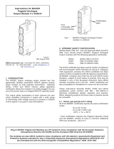
Refer to Figure 1 for a simplified representation of the termination board
configuration.
5.7.1 Power
Connect 24 VDC to the 2-pin removable terminal at the end of the HPSM.
The connector is polarized, so you cannot insert it incorrectly. The polarity
is marked on the terminals. A reverse polarity shunt diode and series fuse
protection are provided to avoid damaging the module in case of accidentally
reversing the polarity connection. In this case, the reverse voltage is clamped
at -1.2 V and the fuse blows. Restore correct supply polarity and replace
the blown fuse. Be certain to reinstall a good, properly sized, new fuse. See
chapter 4.4.1 for fuse specifications.
WARNING!
Improper supply connections can seriously damage the
instrument and result in risk of fire or explosion in hazardous
locations!
Figure 1: Termination Board Configuration

17
NOTE:
DC supply requirements: The MUX is nominally rated for 24
VDC but will function from 21 ... 30 VDC. The MUX draws a
maximum of 50 mA from the supply. If the power LEDs fail to
light, check that the polarity of the supply line is correct.
WARNING!
Note that a crude, poorly filtered, or unregulated supply can
produce destructive (hundreds of volts) voltage spikes during
supply transformer switch-o transient. This could cause
minor problems to electromechanical components like relays
or solenoids but will surely degrade or destroy electronic
equipment.
NOTE:
Supply conductors sizing: Since this HIS board only supplies
power for the MUX, a single unit will require 50 mA and will have
a conductor sizing based on mechanical strength rather than
current carrying capacity. Pepperl+Fuchs recommends 20 AWG
or larger wire be used to power this product.
5.7.2 Grounding
The HPSM provides an earth terminal lug for connecting the various shield
wires to earth. Also included with the HPSM is a DIN rail mountable terminal
block. Use of the terminal lug and terminal block for earth grounding will
provide the shortest path and best practice for grounding of the HPSM. A
10-14 AWG cable should be secured between the terminal lug and DIN rail
block which provides a single point to properly ground field wiring cable
shields. This terminal may not be necessary to use if best practice grounding
techniques are employed.
The HPSM also provides customer selectable capacitive coupling for the
shielding. Setting the shield to be direct coupled or capacitively coupled is
accomplished through jumper shunts. Placing the jumper shunt across the
pins will bypass the capacitor and direct couple the corresponding shield to
earth. Refer to Table 2 for a complete list of the shunts and the associated
shield. For best practice, any shield should be direct coupled at one end of
the circuit.

18
Table 2: Shield Configuration
Jumper Shunt # HISHPSM/32/MM-01
JP1 Channels 1-32 Field
JP2 Channels 1-32 Control
JP3 RS-485
5.7.3 RS-485
An RS-485 network permits up to 32 devices to communicate over a
maximum of 1200 m (4000 ft) of cable. The length of this network can be
extended if necessary by using RS-485 repeaters. The communication
occurs via a dierential signal over a shielded twisted pair of wires. Per the
RS-485 specification the signal wires should be labeled “A” and “B”, but
sometimes a “+” and “-” are used instead. In these cases connect the “+” to
“B” and the “-” to “A”.
NOTE:
A MUX 2700 that is cross-wired on the RS-485 network will not
be damaged, but it also will not communicate.
Since the MUX 2700 is optically isolated it is important to link the signal
grounds of the dierent network nodes to the host ground through the cable
shield. This helps prevent ground potential dierences from causing a loss of
data or damage to equipment on the RS-485 network.
Many cable manufacturers make cable specifically designed for RS-485
networks. Pepperl+Fuchs Elcon recommends using shielded twisted pair
cabling and then utilizing the shield as the RS-485 network ground. This
shield should be grounded at the RS-485 converter if possible.
RS-485 wiring must be connected as shown in Figure 2. These wires carry
data from the HIS to the PC via an RS-485/RS-232 converter cable. Connect
the converter to a serial port on the PC as indicated in the converter’s
documentation.

19
Figure 2: RS-485 Wiring

20
5.7.4 Field connections
All field wiring is connected via the 3-tier screw terminal block (TB1). To
obtain the best results from this device, the use of shielded cables is strongly
recommended. In the case of cable lengths greater than 30 m, shielded
cables are required to ensure proper function of the HPSM. See Figures 3-5
for specific device connections.
Pepperl+Fuchs recommends that all shield drain wires be connected from
as close to TB1 as possible to the nearest grounding point and this point be
linked to earth by as short a route as possible. The HPSM terminal Row B
and the Earth terminal lug have been provided to conveniently allow this.
Unless the transmitter has galvanic isolation between its output and power,
supply the analog loop from the transmitter will link the DCS common to the
transmitter power supply common through terminal Row C.
A
B
C
Field Terminal
Block (TB1)
Transmitter
(4-wire)
4-20mA
Common
Shield
Power
Supply
Figure 4: Self-Powered Transmitters (4-Wire)
Figure 3: Loop-powered Transmitters (2-Wire)
A
B
C
Field Terminal
Block (TB1)
Transmitter
(2-wire)
Shield
Power (+)
4-20mA
/