Page is loading ...

Conventional Flue Log Effect Stove
With Upgradeable Control Valve
Huntingdon 20/30/40
Instructions for Use, Installation and Servicing
For use in GB, IE (Great Britain and Republic of Ireland)
IMPORTANT
THE OUTER CASING, FRONT AND GLASS PANEL BECOME EXTREMELY HOT DURING OPERATION AND WILL RESULT IN SERIOUS
INJURY AND BURNS IF TOUCHED. IT IS THEREFORE RECOMMENDED THAT A FIREGUARD COMPLYING WITH BS 8423 (LATEST EDITION)
IS USED IN THE PRESENCE OF YOUNG CHILDREN, THE ELDERLY OR INFIRM.
ENSURE THAT ALL COMBUSTIBLE MATERIALS ARE NOT POSITIONED ABOVE OR NEAR TO THE APPLIANCE OUTER CASING.
This product contains a heat resistant glass panel. This panel should be checked during Installation and at each servicing interval. If any damage is observed on the
front face of the glass panel (scratches, scores, cracks or other surface defects), the glass panel must be replaced and the appliance must not be used until a
replacement is installed. Under no circumstances should the appliance be used if any damage is observed, the glass panel is removed or broken.
It is essential that ALL of the screws that retain the glass frame are replaced and tightened correctly. Under no circumstances should the appliance be operated if
any of these screws are loose or missing.
These Instructions must be left with the appliance for future reference and for consultation when servicing the appliance. Please make the customer aware of the
correct operation of the appliance before leaving these instructions with them.
The commissioning sheet found on Page 3 of this Instruction manual must be completed by the Installer prior to leaving the premises.
PR1811.13.10.23

2
Appliance Commissioning Checklist ......................3
User Instructions .......................................................4
Installation Instructions ..........................................13
Technical Specifications ........................................................... 13
Site Requirements .................................................................... 15
Installation ................................................................................17
Commissioning ......................................................................... 26
Servicing Requirements .........................................27
Fault Finding .............................................................................27
How to replace parts ................................................................ 29
Basic spare parts list ................................................................ 39
Service Records ....................................................................... 42
Information Requirement - Gas Heaters .................................. 43
Covering the following models:
CONTENTS
It is a requirement of the Building Regulations 2010 that the installation of this appliance is notified to the Local Authority. It is
the responsibility of the GasSafe registered installer to carry out this notification to the Local Authority via the GasSafe register
Competent Persons Scheme in England and Wales (different rules apply in Scotland and Northern Ireland).
When the installation has been notified, GasSafe will send a Building Regulations Compliance Certificate to you containing
details of the work completed. Please ensure that the person responsible for the installation of this appliance completes this
notification and records it in the Appliance Commissioning Checklist on page 3.
IT IS YOUR RESPONSIBILTY TO COMPLY WITH THE BUILDING REGULATIONS AND BE ABLE TO PRODUCE THIS
CERTIFICATE SHOULD IT BE REQUIRED IN THE FUTURE.
If you have purchased your stove or fire from an authorised stockist
within our Expert Retailer Network, then automatically your product
will carry a 2 year warranty as standard. The 2 year warranty can be
further extended to a total warranty period of 5 years by registering
your Gazco Stove or Fireplace within one month of the latter of the
purchase date or installation date. Accordingly, the start date for
the warranty period is the date of purchase. During the registration
process, the Expert Retailer details will be required for your Extended
Warranty to be activated. Any product purchased outside of our Expert
Retailer Network will carry a standard 12 month, non-extendable
warranty.
It is a condition of the Extended Warranty that the installation
complies with the relevant Building Regulations and is carried out
by a suitably trained and qualified individual (GasSafe in the UK or
equivalent in other countries) with the certificate of installation and the
Commissioning Report on Page 3 completed and retained by the end
user.
Full terms and conditions are detailed in the Warranty Statement on
the Gazco website www.gazco.com. In the event of any conflict of
information the wording on the website shall prevail.
Important Note: Should any problems be experienced with your
product, claims must first be submitted to the Expert Retailer where
the appliance was purchased from who will offer immediate assistance
or contact Gazco on your behalf.
Huntingdon 20/30/40 - Conventional Flue
MODEL
HUNTINGDON 20 HUNTINGDON 30 HUNTINGDON 40
NAT GAS LPG NAT GAS LPG NAT GAS LPG
BLACK Tracery Door 515-035 515-405 515-004 515-413 515-161 515-565
Clear Door 515-071 515-441 515-009 515-453 515-188 515-592
IVORY Tracery Door 515-044 515-423 515-154 515-484 515-170 515-574
Clear Door 515-080 515-468 515-061 515-505 515-197 515-601
MATT
IVORY
Tracery Door 515-053 515-432 515-212 515-536 515-179 515-583
Clear Door 515-089 515-477 515-100 515-570 515-206 515-619

3
To assist us in any guarantee claim please complete the following information:-
APPLIANCE COMMISSIONING CHECKLIST
IMPORTANT NOTICE
Explain the operation of the appliance to the end user, hand the completed instructions to them for safe keeping,
as the information will be required when making any guaranteed claims.
Retailer ...............................................
.......................................................
.......................................................
Contact No. ...........................................
Date of Purchase .....................................
Model No. ............................................
Serial No. .............................................
Gas Type .............................................
Installation Company ................................
......................................................
......................................................
Engineer. . . . . . . . . . . . . . . . . . . . . . . . . . . . . . . . . . . . . . . . . . . . .
Contact No. ..........................................
GasSafe Reg No. ....................................
Date of Installation ..................................
RETAILER AND INSTALLER INFORMATION
FLUE CHECK PASS FAIL
1. Flue Is correct for appliance
2. Flue ow Test
3. Spillage Test
GAS CHECK
1. Gas soundness & let by test
2. Standing gas pressure mb
3. Appliance working pressure (on High Setting)
Minimum Pressure Requirement: NG - 17.5mbar LPG - 34.5mbar
NB All other gas appliances must be operating on full
mb
4. Gas rate m3/h
5. Does Ventilation meet appliance requirements
6. Have controls been upgraded (Upgradeable models only) 8455 Standard
8456 Programmable Thermostatic and Timer
YES NO
YES NO
SAFETY CHECK
1. Check soundness of the Thermocouple connections - including tightness and lead integrity
2. Glass checked to ensure no damage, scratches, scores or cracks
3. Glass frame secured correctly and all screws replaced
4. CO Alarm Fitted
BUILDING CONTROL NOTIFICATION YES NO
1. Installer notied GasSafe/Local Authority of installation via Competent Persons Scheme?

4
WELCOME
Congratulations on purchasing your Huntingdon stove, if installed
correctly Gazco hope it will give you many years of warmth and
pleasure for which it was designed.
The purpose of this manual is to familiarise you with your
appliance, and give guidelines for its installation, operation and
maintenance. If, after reading, you need further information, please
do not hesitate to contact your Gazco retailer.
WARNING
In the event of a gas escape or if you can smell
gas, please take the following steps:
• Immediately turn off the gas supply at the
meter/emergency control valve
• Extinguish all sources of ignition
• Do not smoke
• Do not operate any electrical light or power
switches (On or Off)
• Ventilate the building(s) by opening doors
and windows
• Ensure access to the premises can be made
Please report the incident immediately to the
National Gas Emergency Service Call Centre on
0800 111 999 (England, Scotland and Wales) , 0800
002 001 (N. Ireland) or in the case of LPG, the gas
supplier whose details can be found on the bulk
storage vessel or cylinder.
The gas supply must not be used until remedial
action has been taken to correct the defect and
the installation has been recommissioned by a
competent person.
GENERAL
IMPORTANT: ALWAYS WEAR THE GLOVES
PROVIDED WHEN HANDLING AN IVORY PAINTED
APPLIANCE.
Installation and servicing must only be carried out by a competent
person whose name appears on the GasSafe register. To ensure
the engineer is registered with GasSafe they should possess an ID
Card carrying the following logo:
In all correspondence, please quote the appliance type and serial
number, which can be found on the data badge located under the
top plate between the carcass and firebox or on the
Commissioning Checklist on Page 3.
Do not place curtains above the appliance:
You must have 300mm clearance between the appliance and any
curtains at either side.
The manufacturer considers the full outer casing of this appliance
to be a working surface and it will become hot whilst in operation.
A suitable guard is recommended to protect young children, the
aged and the infirm.
No furnishings or other objects should be placed within 1 metre of
the front of the appliance.
If a shelf is fitted, a distance of 225mm above the appliance is
required.
Do not attempt to burn rubbish in this appliance.
This appliance must only be operated with the door secured firmly
in position. If any cracks appear in the glass the appliance must
not be used until the glass panel is replaced.
This product is guaranteed for 5 years from the date of installation,
as set out in the terms and conditions of sale between Gazco and
your local Gazco retailer. Please consult with your local Gazco
retailer if you have any questions. In all correspondence always
quote the Model Number and Serial Number.
CO ALARMS
Building regulations require that whenever a new or replacement
fixed gas burning appliance is installed in a dwelling, a carbon
monoxide alarm complying with BS EN 50291-1(latest edition)
must be fitted in the same room as the appliance. Further guidance
and recommendations on the installation of carbon monoxide
alarms is available in BS EN 50292 (latest edition) and from
manufacturers’ instructions.
Provision of an alarm must not be considered a substitute for
either installing the appliance correctly or ensuring regular
servicing and maintenance of the appliance.
USER INSTRUCTIONS

5
OPERATING THE APPLIANCE
The control valve is at the foot on the right-hand side of the
appliance. It has two controls:
1. The right-hand knob controls the pilot ignition.
2. The left-hand knob controls the main burner.
Refer to separate instructions if your appliance is upgraded to
include battery remote control. The instructions below apply
whether or not you have the remote upgrade.
LIGHTING THE PILOT
To start the left-hand and right-hand control knobs must both point
to off ( ):
Press in the right-hand control knob and rotate anti-clockwise until
a click is heard. Continue to press in. The knob points to the pilot (
).
The pilot is lit.
Keep the knob depressed for 10 seconds before releasing. The
pilot remains lit.
Repeat the above steps if the pilot does not stay lit.
NOTE: If the pilot goes out, the Interlock system prevents you
lighting again for a short period.
If, after repeating the above steps the pilot does not light, contact
your Retailer or Installer.
Turn the right-hand knob to the left to main burner setting
().
ADJUSTING THE FLAME HEIGHT
You can now adjust the flame height and temperature using the
left-hand control knob.
Turn the left-hand knob anti-clockwise to increase the
flame height.
Turn clockwise to decrease the height.
YELLOW FLAMES APPEAR WHEN THE APPLIANCE HAS
REACHED SUFFICIENT HEAT – (10 TO 20 MINUTES).
IF THE APPLIANCE IS EXTINGUISHED OR GOES OUT IN USE,
WAIT 3 MINUTES BEFORE TRYING TO RELIGHT.
TURNING OFF THE APPLIANCE
To turn the main burner off turn the left-hand knob until it points to
off ( ). Just the pilot remains lit.
Press in and turn the right-hand knob until it points to off
(). The pilot goes out.
UPGRADING THE APPLIANCE
The appliance is fitted with a control valve that can easily be
upgraded to battery powered remote control.
There are two versions of this control which can be obtained
through your local Gazco retailer.
There is no requirement for this upgrade to be carried out by an
approved GasSafe engineer. However Gazco recommend that this
task is undertaken by a suitably competent person.
This upgrade can be fitted before or after installation but if side
clearances are limited then it will be easier to upgrade the
appliance before installation. Full instructions are included with the
kit.
If the appliance is left unattended for long periods of
time (e.g. vacation), it is recommended to place the
control valve in the Off or Pilot position.
Take care when leaving the appliance unattended,
in exceptional circumstances sound waves from
sources other than the transmitter can cause
changes in the ame height adjustment.
DO NOT install two or more appliances using
upgradeable controls in the same room, interference
between the remote control frequencies can occur.
STANDARD REMOTE CONTROL
(PART NUMBER 8455)
This remote control can control the gas appliance after the pilot
has been lit. It can turn the main burner on and regulate it from low
through to high and back again.
It can turn the main burner off leaving the pilot burning.
THERMOSTATIC AND TIMER REMOTE CONTROL
(PART NUMBER 8456)
This remote control can control the gas appliance after the pilot
has been lit.
MANUAL MODE
Can be used to turn the main burner on and manually regulate it
from low through to high and back again. It can also be used to
turn the main burner off leaving the pilot burning.
AUTO MODE
Will automatically regulate the room to a pre-set temperature.
TIMER MODE
Will turn the appliance on and off according to a pre-set
programme and automatically regulate the room temperature
during the two on periods.

6
CLEANING THE APPLIANCE
WARNING: NEVER CLEAN THE APPLIANCE
WHILE IT’S HOT. THE APPLIANCE STAYS HOT
FOR A LONG TIME AFTER SHUTDOWN.
IMPORTANT: THE OUTER PANELLING OF THE
APPLIANCE IS MADE FROM CAST IRON. USE
CAUTION WHEN INSTALLING, REMOVING AND
STORING AS THE COMPONENTS ARE HEAVY
AND SHOULD BE HANDLED CAREFULLY.
Make sure the appliance and surrounds are cool before cleaning.
REMOVING THE DOOR
For rear flue exit lift the top of the appliance off and put to one
side.
For top flue exit lift and support the top to give clearance.
HUNTINGDON 20 AND 40
Supporting the door top and bottom pull forwards whilst lifting the
front upwards at a 45° angle until it is clear of the slots and pull
away from the appliance.
HUNTINGDON 30
Lift the front upwards until it is clear of the slots and pull away from
the appliance.
ALL MODELS
Remove the glass frame by undoing the fixing screws and lifting
clear. Take care to support the glass window panel when
removing the screws.
Place carefully to one side.
Lift out the log guard.
Carefully remove the ceramic fuel bed components and set aside.
Protect the floor coverings and follow the advice given.
The logs do not require cleaning. Do not use a vacuum cleaner or
brush to clean the logs, any large pieces of debris can be removed
by hand.
Ensure any debris is removed from the burner ports.
Replace the ceramics see Log Layout section.
Ensure that the fibreglass seal on the back of the glass frame is
intact and replace the screws working from the top down. Tighten
the screws evenly DO NOT OVER TIGHTEN.
NEVER OPERATE THE APPLIANCE WHEN THE GLASS
FRAME IS REMOVED OR BROKEN.
Replace ALL of the securing screws ensuring that a screw is
present in all fixing slots.
UNDER NO CIRCUMSTANCES SHOULD THE
APPLIANCE BE USED IF ANY OF THE GLASS
FRAME RETAINING SCREWS ARE LOOSE OR
MISSING.
Use a damp cloth to clean the outer casing of the appliance.

7
CLEANING IVORY PAINTED
APPLIANCES
Allow the appliance to cool thoroughly to avoid risk of burns.
Ivory painted appliances require special attention when cleaning.
They have been coated with a high quality paint that should give
many years of service. However, this colour will mark more easily
and require cleaning more than other models.
Take care when touching the appliance to avoid marking the paint.
Most marks can be removed using a mild soap solution and a
clean lint free cloth. The finish can also be refreshed using aerosol
touch up paint (product code 2055) available from your Gazco
retailer.
ARRANGEMENT OF FUEL BED
ADVICE ON HANDLING AND DISPOSAL OF FIRE CERAMICS
The fuel effect of the log version of this
appliance is made from Refractory Ceramic
Fibre (RCF), a material which is commonly used
for this application.
Protective clothing is not required when
handling these articles, but we recommend you
follow normal hygiene rules of not smoking,
eating or drinking in the work area and always
wash your hands before eating or drinking.
To ensure that the release of RCF fibres are kept
to a minimum, during installation and servicing a
HEPA filtered vacuum is recommended to
remove any dust accumulated in and around the
appliance before and after working on it. When
servicing the appliance it is recommended that
the replaced items are not broken up, but are
sealed within heavy duty polythene bags and
labelled as RCF waste.
RCF waste is classed as stable, non-reactive
hazardous waste and may be disposed of at a
licensed landfill site.
Excessive exposure to these materials may
cause temporary irritation to eyes, skin and
respiratory tract; wash hands thoroughly after
handling the material.
LOGS MUST BE POSITIONED ACCORDING TO THE
FOLLOWING INSTRUCTIONS TO GIVE THE CORRECT FLAME
EFFECT.
LOG LAYOUT
HUNTINGDON 20
All logs can be identified by a letter (A - E) on their underside. Logs
B and E also have holes to locate each onto a burner stud.
Ensure the burner tray is clean and free from any debris.
Place Log A on the higher rear bracket and push up against the
back panel.
Place Log B over the two middle studs on the burner tray.

8
Place Log E onto the stud and behind the tag on the left hand side
of the burner tray.
Rest against Log B.
Place the small Ember at the front left of the firebox against the
rear of the log support bracket to obscure the reflection of the
burner screw.
Place the larger Ember on the lower bracket above the pilot on the
right hand side with the thicker edge facing the front and flat edges
to the base and side.
Place the foot of Log C into the rear left hand corner. The long flat
edge rests against the side of the firebox and the log touches the
back panel. The top of the log rests on Log E.
Detail A
A
Place the pointed bottom of log D into the corner of the burner tray
and rest on the location stud in log B.
Sparingly spread an amount of the Embaglow fibres provided,
covering the ports in the burner tray. Use a small piece in front of
the log on the left hand side and a long strip in front of log B.
Take care not to use more than half a packet per application.
WARNING - DO NOT PLACE NEAR THE PILOT AREA.
Embaglow
Lower log guard into position.

9
HUNTINGDON 30
Ensure the burner tray is clean and free from any debris.
The three logs that make up the fuel bed are visually distinct and fit
into specific parts on the burner tray.
Place the rear log into position between the rear brackets and
pushed up against the back panel.
Log 1
Place the second log into the left hand groove on the burner tray.
The log should butt up against the raised molding and the left hand
side liner.
Log 2
Place the third log into the groove on the right hand side.
The log should butt up against the raised molding and the right
hand side liner.
Log 3
Once the logs are in there are two embers which can be loosely
placed at the front of the fuel bed and cover the tabs securing the
burner tray.
Embers
Sparingly spread an amount of the Embaglow fibres provided,
covering the ports in the burner tray.
It is essential to cover the port in the middle of the burner tray
in order to get the most visually appealing flame picture.
Take care not to use more than half a packet per application.
WARNING - DO NOT PLACE NEAR THE PILOT AREA.
It is essential to
cover the
central port
Embaglow

10
Fix log guard into position.
HUNTINGDON 40 LAYOUT
The logs for the fuel bed are clearly individually labelled,
A to D.
Ensure the burner tray is clean and free from any debris.
There are 3 embers. Place 2 embers in the back corners of the
burner, resting in the cut outs.
Place the last ember loosely at the front of the fuel bed to cover
the hole in the centre.
Place Log D on the left hand side of the burner. There is a hole on
the underside of Log D which fits over the raised stud on the left of
the burner. The back of the log should rest flat against the back
panel.
Place Log B on top of Log D. There is a hole on the underside of
Log B which fits over the raised stud on Log D to secure in place.
The right hand side of the log rests in the groove in the burner.
Place Log C on the right hand side of the burner. There is a hole
on the underside of Log C which fits over the raised stud on the
right of the burner. The back of the log should rest flush against the
back panel.

11
Place the log guard into position on the grooves on the sides of the
firebox.
Place Log A across Log C. There is a hole on the underside of Log
A which fits over the raised stud on Log C to secure in place. The
small cut out on the left side of the log rests onto the log guard.
Once the logs are in place sparingly spread an amount of the
Embaglow fibres provided on the sections highlighted.
Take care not to use more than half a packet per application.
IT IS ESSENTIAL TO KEEP THE REAR PORT FREE FROM
OBSTRUCTION.
WARNING - DO NOT PLACE NEAR THE PILOT AREA.
Keep Rear
Port free from
Embaglow
Use a ceramic glass product generally sold for cleaning ceramic
hobs to clean the glass front.
The glass frame must be refitted to the appliance following
cleaning or servicing.
Ensure that the rope seal on the back of the glass frame is intact
and replace the screws working from the top down. Tighten the
screws evenly DO NOT OVER TIGHTEN.
Replace ALL of the securing screws ensuring that a screw is
present in all fixing slots.
UNDER NO CIRCUMSTANCES SHOULD THE
APPLIANCE BE USED IF ANY OF THE FRAME
RETAINING SCREWS ARE LOOSE OR MISSING.
NEVER OPERATE THE APPLIANCE WHEN THE GLASS
FRAME IS REMOVED, OR THE GLASS IS BROKEN.
With the top still supported or removed refit front by locating in
grooves and lowering into place.
Now replace top.

12
FLUE SURE SYSTEM
The appliance is fitted with the Gazco Flue Sure System, which will
act to cut off the gas supply to the burners in the event of incorrect
operation of the flue. If the system acts to cut off the gas supply,
this indicates that there is insufficient flue pull. If this occurs a
minimum of 10 minutes should be allowed before trying to relight.
Continued operation of this safety device means there may be a
serious problem with the flue system. A qualified GasSafe engineer
should inspect this.
DO NOT USE THE APPLIANCE UNTIL AN ENGINEER SAYS IT
IS SAFE TO DO SO.
FLAME FAILURE DEVICE
This is a safety feature incorporated on this appliance which
automatically switches off the gas supply if the pilot goes out and
fails to heat the thermocouple.
IF THIS OCCURS DO NOT ATTEMPT TO RELIGHT THE
APPLIANCE FOR 3 MINUTES.
RUNNING IN
1During initial use of a new Gazco appliance a strong odour will be
encountered as various surface coatings become hot for the first
time. Although these odours are harmless it is recommended that
the appliance is operated on maximum for 4 to 8 hours in order to
fully burn off these coatings. After this period the odours should
then disappear.
If the odours persists, please contact your installer for advice.
During the first few hours of burning there may be discolouration of
the flames. This will also disappear after a short period of use.
SERVICING
Servicing and Support
To keep your appliance looking and performing at its best, it must
be serviced annually. This service must be undertaken by a suitably
qualied individual and your retailer can organise this for you.
Alternatively, Gazco offer a manufacturers premium service with our
friendly team of qualied engineers which can be booked at
www.gazco.com/support
In all correspondence always quote the Model number and the
Serial number which may be found on the Commissioning Checklist
(Page 3).
VENTILATION
This appliance requires no additional ventilation.
INSTALLATION DETAILS
Your installer should have completed the commissioning sheet at
the front of this book. This records the essential installation details
of the appliance. In all correspondence always quote the Model
number and Serial number.
HOT SURFACES
Parts of this appliance become hot during normal use.
Regard all parts of the appliance as a ‘working surface’.
Provide a suitable fire guard to protect young children and the
infirm.
PILOT AREA WHITENING
Gas re owners (not exclusive to Gazco) have reported issues of
whitening around the pilot areas on their Conventional Flue glass
fronted products. These white marks can also appear on glass or
enamel panels inside the re and on the inside of the glass which
chemical analysis found to be Silicon Dioxide.
The cause of this is most likely a heat decomposition product of
Siloxanes or similar compounds. Gazco can conrm that there
are no Siloxane or similar products used in our conventionally
ued res and is therefore forming from sources external to the
appliance. Siloxanes can be widely found in domestic cleaning
products, cosmetics, scented room diffusers, candles and
biomethane in the natural gas supply.
To reduce this problem, Gazco would recommend the removal of
any products that could possibly contain Siloxanes from the room
the re is situated in. In addition to this, the whitening appears to
be worse when the product is left for long periods of time in the
pilot only position. This should be reduced where customers are
experiencing this problem.

13
TECHNICAL SPECIFICATION
Covering the following models:
MODEL APP.
CAT. GAS TYPE WORKING
PRESSURE AERATION INJECTOR GAS RATE
M3/H
INPUT KW
(GROSS) COUNTRY
HIGH LOW
HUNTINGDON 20
I2H Natural Gas (G20) 20mbar 1x ø6mm 185 0.314 3.3 2.0 GB, IE
I3P Propane (G31) 37mbar 6mm x 15mm 90 0.120 3.2 2.0 GB, IE
HUNTINGDON 30
I2H Natural Gas (G20) 20mbar 6mm x 6mm 260 0.433 4.55 2.5 GB, IE
I3P Propane (G31) 37mbar 1 x (14mm x 15mm) 102 0.164 4.35 2.5 GB, IE
HUNTINGDON 40
I2H Natural Gas (G20) 20mbar 2 x ø6mm 067 0.628 6.6 3.9 GB, IE
I3P Propane (G31) 37mbar 2 x ø13mm 128 0.252 6.7 3.7 GB, IE
Huntingdon 20: Efciency Class 2 - 76% / NOx Class 4
Huntingdon 30: Efciency Class 2 - 75% / NOx Class 4
Huntingdon 40: Efciency class 2 - 78%
Flue Outlet Size 127mm (5”) ø
Gas Inlet Connection Size 8mm ø
Minimum ue specication T250 / N2 / O / D / 1
Maximum ue temperature 220°C
MODEL
HUNTINGDON 20 HUNTINGDON 30 HUNTINGDON 40
NAT GAS LPG NAT GAS LPG NAT GAS LPG
BLACK Tracery Door 515-035 515-405 515-004 515-413 515-161 515-565
Clear Door 515-071 515-441 515-009 515-453 515-188 515-592
IVORY Tracery Door 515-044 515-423 515-154 515-484 515-170 515-574
Clear Door 515-080 515-468 515-061 515-505 515-197 515-601
MATT
IVORY
Tracery Door 515-053 515-432 515-212 515-536 515-179 515-583
Clear Door 515-089 515-477 515-100 515-570 515-206 515-619
The net efficiency of this appliance has been measured as specified in EN613:2001 and the result after conversion
to gross using the appropriate factor from Table E4 of SAP 2012 is 69.1% (Huntingdon 20 and 30) or 71.8%
(Huntingdon 40). The test data has been certified by Kiwa Nederland B.V. The gross efficiency value may be used in
the UK Government's Standard Assessment Procedure (SAP) for energy rating of dwellings.
INSTALLATION INSTRUCTIONS
This appliance has been certified for use in countries other than those stated. To install this appliance in these countries, it is essential to
obtain the translated instructions and in some cases the appliance will require modification. Contact Gazco for further information.

14
PACKING CHECKLIST
QTY DESCRIPTION FIXING KIT CONTAINING:-
1 x Appliance
1 x Flue infill plate
1 x Log set
1 x Packet of Embaglow
1 x Instruction manual
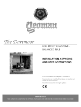
HUNTINGDON 40
A B C D E F G
Huntingdon 40 641 653 382 460 99 154 350
D
B
C
A
E
G
F
F
G
B
D
C
E
HUNTINGDON 20 & 30
A B C D E F G
Huntingdon 20 419 535 320 366 62 119 266
Huntingdon 30 552 592 357 402 96 174 305
A
DIMENSIONS (mm)

15
SITE REQUIREMENTS
FLUE & CHIMNEY REQUIREMENTS
The chimney or flue system must comply with the rules in force,
and must be a minimum of 127mm (5") in diameter.
The minimum flue height for the appliance must be 3 metres (10ft).
Any horizontal flue run from the rear outlet must not exceed
100mm from the back of the appliance.
A minimum of 100mm vertical flue above the top outlet spigot
should be provided before any offset of the flue.
The chimney or flue must be free from any obstruction. Any
damper plates must be removed or secured in the fully open
position, and no restrictor plates fitted.
The chimney must be swept prior to the installation, but it need not
be swept if it can be seen the chimney is clean and unobstructed
throughout its entire length.
A 5" (127mm) liner must be used if fitting the appliance into an
existing brick built chimney.
Larger lined flues can work, but in some instances could cause
cold start flue problems resulting in nuisance shutdown. Lined flues
above 7" (175mm) are not recommended.
The European chimney standards now describe chimneys and
flues by their temperature, pressure and resistance to corrosion,
condensation and fire. To identify the correct flue system, the
minimum flue specification is shown in the Technical Specification.
Existing chimneys are not covered by this system.
FLUE OPTIONS
A range of Vitreous Enamel Gloss Black flue pipe is available
to compliment the Huntingdon. Please contact your Gazco
retailer for further information.
GAS SUPPLY
THIS APPLIANCE IS INTENDED FOR USE ON A GAS
INSTALLATION WITH A GOVERNED METER.
Before installation, ensure that the local distribution conditions
(identification of the type of gas and pressure) and the adjustment
of the appliance are compatible.
Ensure the gas supply delivers the required amount of gas and is
in accordance with the rules in force.
You can use soft copper tubing on the installation and soft soldered
joints outside the appliance and below the fire.
A means of isolating the gas supply to the appliance must be
provided independent of any appliance control.
All supply gas pipes must be purged of any debris that may have
entered prior to connection to the appliance.
The gas supply must be installed in a way that does not restrict the
removal of the appliance for servicing and inspection.
VENTILATION
IMPORTANT: Ensure any national ventilation requirements are
taken into account during installation of the appliance.
UK ONLY:
The Huntingdon 30 has a nominal input not exceeding 7.0kW and
does not normally require any additional permanent ventilation.
FOR THE REPUBLIC OF IRELAND REFER TO THE RULES IN
FORCE FOR VENTILATION REQUIREMENTS.
CO ALARMS
Building regulations require that whenever a new or replacement
fixed gas burning appliance is installed in a dwelling, a carbon
monoxide alarm complying with BS EN 50291-1(latest edition)
must be fitted in the same room as the appliance. Further guidance
and recommendations on the installation of carbon monoxide
alarms is available in BS EN 50292 (latest edition) and from
manufacturers’ instructions.
Provision of an alarm must not be considered a substitute for
either installing the appliance correctly or ensuring regular
servicing and maintenance of the appliance.
APPLIANCE LOCATION
Building Regulations state this appliance must stand on a non-
combustible hearth that is at least 12mm thick and projects 50mm
minimum from the base of the appliance in all directions, however
Gazco recommend the hearth extends to the following dimensions.
C
A
B
DIMENSION A B C
Huntingdon 20 716 420 12
Huntingdon 30 853 451 12
Huntingdon 40 941 482 12

16
MINIMUM CLEARANCE
The appliance is not suitable for installation against a combustible
wall.
Ensure that all minimum clearances to combustible materials
are complied with.
The specified clearances provide the minimum distance to
combustible materials. If the appliance is intended to be installed
into a non-combustible opening the clearance to the sides and
above the appliance can be reduced. However, it is recommended
that the specified clearances are maintained irrespective of the
materials used in the construction of the opening to allow adequate
air flow and access to controls. The clearance at the rear of the
appliance must always be a minimum of 50mm.
150
225
150
50mm
150mm
In a non-combustible recess be careful to allow enough
clearance at the sides and rear of the appliance to perform
spillage tests and reach the controls.

17
SAFETY PRECAUTIONS
IMPORTANT: ALWAYS WEAR THE GLOVES
PROVIDED WHEN HANDLING AN IVORY PAINTED
APPLIANCE.
For your own and other’s safety, you must install this appliance
according to local and national codes of practice. Failure to install
the appliance correctly could lead to prosecution. Read these
instructions before installing and using this appliance.
These instructions must be left intact with the user.
Do not attempt to burn rubbish on this appliance.
Keep all plastic bags away from young children.
Do not place any object on or near to the appliance and allow
adequate clearance above the appliance.
IF THE APPLIANCE IS EXTINGUISHED OR GOES OUT IN USE,
WAIT 3 MINUTES BEFORE ATTEMPTING TO RELIGHT THE
APPLIANCE.
The appliance is fitted with the Gazco Flue Sure System, which will
act to cut off the gas supply to the burners in the event of incorrect
operation of the flue. If the system acts to cut off the gas supply,
this indicates that there is insufficient flue pull. If this occurs a
minimum of 10 minutes should be allowed before trying to relight.
Continued operation of this safety device means there may be a
serious problem with the flue system. A qualified GasSafe engineer
should inspect this.
Do not alter or tamper with the Flue Sure System. Use only
genuine Gazco replacement parts when servicing the system -
refer to the Servicing Section, Replacing Parts.
DO NOT USE THE APPLIANCE UNTIL AN ENGINEER SAYS IT
IS SAFE TO DO SO.
IMPORTANT: REFER TO DATA BADGE AND
TECHNICAL SPECIFICATION AT THE FRONT OF
THE MANUAL TO ENSURE THE APPLIANCE IS
CORRECTLY ADJUSTED FOR THE GAS TYPE AND
CATEGORY APPLICABLE IN THE COUNTRY OF
USE.
UNPACKING
Remove the appliance from its packaging, and check that it is
complete and undamaged.
Put the loose ceramic parts to one side so that they are not
damaged during installation.
UPGRADING THE APPLIANCE
The appliance is fitted with a control valve that can easily be
upgraded to battery powered remote control.
There are two versions of this control which can be obtained
through your local Gazco retailer.
There is no requirement for this upgrade to be carried out by an
approved GasSafe engineer. However Gazco recommend that this
task is undertaken by a suitably competent person.
This upgrade can be fitted before or after installation but if side
clearances are limited then it will be easier to upgrade the
appliance before installation. Full instructions are included with the
kit.
If the appliance is left unattended for long periods of
time (e.g. vacation), it is recommended to place the
control valve in the Off or Pilot position.
Take care when leaving the appliance unattended,
in exceptional circumstances sound waves from
sources other than the transmitter can cause
changes in the ame height adjustment.
DO NOT install two or more appliances using
upgradeable controls in the same room, interference
between the remote control frequencies can occur.
STANDARD REMOTE CONTROL
(PART NUMBER 8455)
This remote control can control the gas appliance after the pilot
has been lit. It can turn the main burner on and regulate it from low
through to high and back again.
It can turn the main burner off leaving the pilot burning.
THERMOSTATIC AND TIMER REMOTE CONTROL
(PART NUMBER 8456)
This remote control can control the gas appliance after the pilot
has been lit.
MANUAL MODE
Can be used to turn the main burner on and manually regulate it
from low through to high and back again. It can also be used to
turn the main burner off leaving the pilot burning.
AUTO MODE
Will automatically regulate the room to a pre-set temperature.
TIMER MODE
Will turn the appliance on and off according to a pre-set
programme and automatically regulate the room temperature
during the two on periods.
INSTALLATION

18
INSTALLATION OF THE APPLIANCE
Decide whether to use top or rear flue exit.
The appliance is factory built for rear flue exit but it can be
changed to top exit by swapping the flue spigot and blanking plate
located on the appliance.
HUNTINGDON 30 ONLY
On Huntingdon 30 models the flue spigot must be placed in an
offset position from the blanking plate to correctly align with the top
plate.
To access the blanking plate lift off the cast top and place carefully
to one side.
Remove the four screws holding the blanking plate to the
appliance.
Note the two additional holes in the top of the firebox.
With the blanking plate removed there are a two additional holes
underneath.
Position the flue spigot using the offset holes and the ones
previously beneath the blanking plate. Secure the spigot and
blanking plate in the new positions.
ALL MODELS
Position the appliance ensuring all appropriate clearances are
observed.
Having run the gas supply to the appliance PURGE THE SUPPLY
PIPE.
This is essential to expel any debris that can block the gas
controls.
Connect the gas supply to the 8mm compression elbow at the
right-hand rear corner of the appliance.
There is a cutout in the right-hand rear leg to enable a straight
connection to the rear of the appliance.
The flue system can now be connected to the appliance.
Ensure all joints are sealed with a fire resistant cement and use a
self-tapping screw at the flue spigot joint.
GAS SOUNDNESS PRESSURE CHECK
Connect a suitable pressure gauge to the test point located on the
inlet fitting and turn the gas supply on. Light the appliance and
check all gas joints for possible leaks. Turn the appliance to
maximum and check that the supply pressure is as stated on the
databadge. Turn the gas off and replace the test point screw, turn
the gas on and check the test point for leaks.

19
REMOVING THE DOOR
IMPORTANT: THE OUTER PANELLING OF THE
APPLIANCE IS MADE FROM CAST IRON. USE
CAUTION WHEN INSTALLING, REMOVING AND
STORING AS THE COMPONENTS ARE HEAVY
AND SHOULD BE HANDLED CAREFULLY.
For rear flue exit lift the top of the appliance off and put to one
side.
For top flue exit lift and support the top to give clearance.
HUNTINGDON 20 AND 40
Lift the front upwards until it is clear of the slots and pull away from
the appliance.
HUNTINGDON 30
Lift the front upwards until it is clear of the slots and pull away from
the appliance.
ALL MODELS
Remove the glass frame by undoing the fixing screws and lifting
clear. Take care to support the glass window panel when
removing the screws.

20
ARRANGEMENT OF FUEL BED
ADVICE ON HANDLING AND DISPOSAL OF FIRE CERAMICS
The fuel effect of the log version of this
appliance is made from Refractory Ceramic
Fibre (RCF), a material which is commonly
used for this application.
Protective clothing is not required when
handling these articles, but we recommend you
follow normal hygiene rules of not smoking,
eating or drinking in the work area and always
wash your hands before eating or drinking.
To ensure that the release of RCF fibres are
kept to a minimum, during installation and
servicing a HEPA filtered vacuum is
recommended to remove any dust
accumulated in and around the appliance
before and after working on it. When servicing
the appliance it is recommended that the
replaced items are not broken up, but are
sealed within heavy duty polythene bags and
labelled as RCF waste.
RCF waste is classed as stable, non-reactive
hazardous waste and may be disposed of at a
licensed landfill site.
Excessive exposure to these materials may
cause temporary irritation to eyes, skin and
respiratory tract; wash hands thoroughly after
handling the material.
LOG LAYOUT
HUNTINGDON 20
LOGS MUST BE POSITIONED ACCORDING TO THE
FOLLOWING INSTRUCTIONS TO GIVE THE CORRECT FLAME
EFFECT.
All logs can be identified by a letter (A - E) on their underside.
Logs, B and E also have holes to locate each onto a burner stud.
Ensure the burner tray is clean and free from any debris.
Place Log A on the higher rear bracket and push up against the
back panel.
Place Log B over the two middle studs on the burner tray.
Place Log E onto the stud and behind the tag on the left hand side
of the burner tray.
Rest against Log B.
/