Page is loading ...

IOG-2025C
08/21
WARNING
19001 Kermier Rd. Waller, Tx 77484
www.goodmanmfg.com•www.amana-hac.com
© 2020-2021 Goodman Manufacturing Company, L.P.
is a registered trademark of Maytag Corporaon or its related companies and is used under license. All rights
reserved.
These furnaces comply with requirements embodied
in the American National Standard/National Standard
of Canada ANSI Z21.47•CSA-2.3 Gas Fired Central
Furnaces.
Installer:
Ax all manuals
adjacent to the unit.
As a professional installer you have an obligation to know
the product better than the customer. This includes all
safety precautions and related items.
Prior to actual installation, thoroughly familiarize yourself
with this Instruction Manual. Pay special attention to all
safety warnings. Often during installation or repair it is
possible to place yourself in a position which is more
hazardous than when the unit is in operation.
Remember, it is your responsibility to install the product
safely and to know it well enough to be able to instruct a
customer in its safe use.
Safety is a matter of common sense...a matter of thinking
safety practices...follow them.
The precautions listed in this Installation Manual are
intended as supplemental to existing practices. However,
the content of this manual, the precautions listed here take
precedence.

2
3
5
8
10
10
13
18
21
28
31
34
34
34
34
34
34
34
44
This device, which was assembled by Goodman Manufacturing
QOQBGM111. And this international radiator has an Industry Canada
(1) This device may not cause harmful interference; and
(2) This device must accept any interference received, including
interference that may cause undesirable operation.
And this device meets the applicable Industry Canada technical
The manufacturer of the intentional radiator (model no. BGM111) is
Silicon Laboratories Finland Oy, which can be contacted by calling 617-
Goodman Manufacturing Company, L.P. may be contacted by calling
(www.goodmanMFG.com)
This equipment has been tested and found to comply with
Rules. These limits are designed to provide reasonable protection
against harmful interference in a residential installation. This equipment
generates, uses and can radiate radio frequency energy and, if not
installed and used in accordance with the instructions, may cause
harmful interference to radio communications. However, there is no
guarantee that interference will not occur in a particular installation. If
this equipment does cause harmful interference to radio or television
on, the user is encouraged to try to correct the interference by one or
—Reorient or relocate the receiving antenna.
—Increase the separation between the equipment and
receiver.
from that to which the receiver is connected.
—Consult the dealer or an experienced radio/ TV technician
for help.
This equipment complies with FCC radiation exposure limits. To ensure
compliance, human proximity to the antenna shall not be less than
WARNING
CHANGES OR MODIFICATIONS NOT EXPRESSLY APPROVED BY THE PARTY
RESPONSIBLE FOR COMPLIANCE COULD VOID THE USER’S AUTHORITY TO
OPERATE THE EQUIPMENT.

3
This unit has a control system that compensates for certain
• Be properly installed, operated, and maintained per
the instructions.
• Be serviced only by properly trained service
technicians.
Units that are not installed, maintained, or operated
properly may result in “noisy” operation during the heating
cycle. If this unit is making unusual or objectionable noises
Adhere to the following warnings and cautions when
installing, adjusting, altering, servicing, or operating the
furnace. To ensure proper installation and operation,
installation and application of this product.
This furnace is manufactured for use with natural gas only.
Install this furnace only in a location and position
section and
section of this manual.
Provide adequate combustion and ventilation air to the
section of this manual.
Combustion products must be discharged to the outdoors.
Connect this furnace to an approved vent system only, as
section of this manual.
in section of this manual.
intended temperature-rise range with a duct system which
has external static pressure within the allowable range,
Checks section of these instructions.
air circulated by the furnace to areas outside the space
containing the furnace, the return air shall also be handled
by duct(s) sealed to the furnace casing and terminating
outside the space containing the furnace.
section of this
manual.
This furnace cannot be used as a construction site heater.
CAUTION
WARNING
WARNING

4
WARNING
WARNING
WARNING
CO can cause serious illness including permanent brain
damage or death.
Advertencia especial para la instalación de calentadores ó manejadoras
de aire en áreas cerradas como estacionamientos ó cuartos de servicio.
El monóxido de carbono puede causar enfermedades severas
como daño cerebral permanente ó muerte.
Las emisiones de monóxido de carbono pueden circular a través
del aparato cuando se opera en cualquier modo.
RISQUE D'EMPOISONNEMENT AU MONOXYDE DE CARBONE
Cette ventilation est nécessaire pour éviter le danger d'intoxication
au CO pouvant survenir si un appareil produisant du monoxyde
de carbone continue de fonctionner au sein de la zone confinée.

5
All units are securely packed in shipping containers
tested according to International Safe Transit Association
for external damage. If damage is found, a request for
immediately.
The furnace must be carefully inspected on arrival for
damage and bolts or screws which may have come loose
1. Make a notation on delivery receipt of any visible
damage to shipment or container.
2. Notify carrier promptly and request an inspection.
3.
4. File the claim with the following support documents
within a nine month statute of limitations.
•
indemnity bond.
• Original paid freight bill or indemnity in lieu thereof.
•
and other discounts or reductions.
•
representative at the time damage is reported to
carrier.
The carrier is responsible for making prompt inspection of
damage and for a thorough investigation of each claim.
The distributor or manufacturer will not accept claims from
dealers for transportation damage.
Use the following precautions during furnace installation
and servicing to protect the integrated control module
from damage. By putting the furnace, the control, and
the person at the same electrostatic potential, these steps
will help avoid exposing the integrated control module to
electrostatic discharge. This procedure is applicable to
both installed and non-installed (ungrounded) furnaces.
1.
the integrated control module or any wire connected
electrostatic charge to ground.
2. Firmly touch a clean, unpainted, metal surface of
the furnaces near the control. Any tools held in a
3. Service integrated control module or connecting
wiring following the discharge process in step 2.
Use caution not to recharge your body with static
not touch ungrounded objects, etc.). If you come
in contact with an ungrounded object, repeat step 2
before touching control or wires.
4.
new control from its container. Follow steps 1 through
3 if installing the control on a furnace. Return any old
or new controls to their containers before touching
any ungrounded object.
Before installing this unit, please read this manual
maximum external static pressure, gas pressures, BTU
input rating, proper electrical connections, circulating air
temperature rise, minimum or maximum CFM, and motor
speed connections.
WARNING
This furnace is primarily designed for residential home-
use in mobile homes, trailers or recreational vehicles.
The furnace must be installed indoors (i.e., attic space,
crawl space, or garage area provided the garage area is
enclosed with an operating door).
This furnace can be used in the following non-industrial
In such applications, the furnace must be installed with the
• It must be installed per the installation instructions
provided and per local and national codes.
• It must be installed indoors in a building constructed
on site.
• It must be part of a ducted system and not used in a
free air delivery application.
• It must not be used as a “make-up” air unit.
• It must be installed as a two-pipe systems for
combustion air.
• All other warranty exclusions and restrictions apply
appropriate for use with natural gas.
•
• Non-direct vent (single pipe) central forced air furnace
in which combustion air is taken from the installation
area or from air ducted from the outside or,

6
•
which all combustion air supplied directly to the
furnace burners through a special air intake system
outlined in these instructions.
• The furnace has a permanently installed venting
system per these installation instructions.
• A room thermostat is used to control the furnace.
Fixed jumpers that provide continuous heating
CANNOT be used and can cause long term
equipment damage. Bi-metal thermostats or any
during construction.
• The furnace is attached to permanent return air
ducting sealed to the furnace.
•
•
the system and inspected daily and replaced as
needed during construction and upon completion of
construction.
• The input rate and temperature rise settings are within
furnace rating plate guidelines.
• The furnace must be installed as a two-pipe system,
construction.
• The furnace heat exchanger, components, duct
• All furnace operating conditions, including ignition,
instructions.
• Furnace doors must be in place on the furnace while
the furnace is operating in any mode.
To ensure proper furnace operation, install, operate and
maintain the furnace in accordance with these installation
and operation instructions, all local building codes and
ordinances. In their absence, follow the latest edition
Installation Codes, local plumbing or waste water codes,
and other applicable codes.
American National Standards Institute
National Fire Protection Association
1 Batterymarch Park
CSA International
The rated heating capacity of the furnace should be greater
than or equal to the total heat loss of the area to be heated.
The total heat loss should be calculated by an approved
method or in accordance with “ASHRAE Guide” or “Manual
J-Load Calculations” published by the Air Conditioning
Contractors of America.
WARNING
WARNING
Follow the instructions listed below and the guidelines
provided in the Combustion and Ventilation Air
Requirements section when selecting a furnace location.
• Centrally locate the furnace with respect to the
proposed or existing air distribution system.
• Ensure the temperature of the return air entering the
is heating.
• Provide provisions for venting combustion products
outdoors through a proper venting system. Special
and combustion air intake pipe when applicable.
Refer to Vent/Flue Pipe and Combustion Air Pipe
-Termination Locations for appropriate termination
locations and to determine if the piping system from
furnace to termination can be accomplished within
or combustion air piping can be a limiting factor in the
location of the furnace.
•
condensate drainage system in any area subject to
below freezing temperatures without proper freeze
for further details.

7
• Ensure adequate combustion air is available for the
can expose building occupants to gas combustion
products that could include carbon monoxide. Refer
to Combustion and Ventilation Air Requirements.
•
a concrete base sized approximately 1-1/2” larger
than the base of the furnace. Refer to the Horizontal
Applications and Considerations for leveling of
horizontal furnaces.
•
directly on carpeting, or any other combustible
material. The only combustible material allowed is
wood.
• Exposure to contaminated combustion air will result
not install the furnace where the combustion air is
• Permanent wave solutions
• Chlorinated waxes or cleaners
• Chlorine-based swimming pool chemicals
• Carbon tetrachloride
• Swimming pool chemicals
• Halogen type refrigerants
• Printing inks
• Cleaning solutions (such as perchloroethylene)
• Paint removers
• Varnishes
• Hydrochloric acid
• Cements and glues
• Antistatic fabric softeners for clothes dryers
• Masonry acid washing materials
• Protect a non-direct vent furnace from airborne
contaminants. To ensure that the enclosed non-direct
vent furnace has an adequate supply of combustion
air, vent from a nearby uncontaminated room or from
outdoors. Refer to the Combustion and Ventilation Air
Requirements for details.
• If the furnace is used in connection with a cooling coil
unit, install the furnace upstream or in parallel with the
cooling coil unit. Premature heat exchanger failure
will result if the cooling unit is placed ahead of the
furnace.
coil width shall not be less than furnace width minus 1”.
be the same width as the furnace or may be one size
installed with a “B” width furnace.
must face the same direction.
• If the furnace is installed in a residential garage,
position the furnace so that the burners and ignition
Protect the furnace from physical damage by vehicles.
• If the furnace is installed horizontally, ensure the
access doors are not on the “up/top” or “down/bottom”
side of the furnace.
•
serves a separate appliance designed to burn solid
fuel.
• For servicing or cleaning, a 24” front clearance is
required.
•
necessitate greater clearances than the minimum
clearances listed above.
• In all cases, accessibility clearance must take
precedence over clearances from the enclosure
where accessibility clearances are greater.
POSITION* SIDES REAR FRONT BOTTOM FLUE TOP
Upflo w 0" 0" 3" C0" 1"
Horizontal 6" 0" 3" C0" 6"
C = If placed on combustible floor, floor MUST be wood only.
*M VS96 M INIM UM CLEARANCES
TO COMBUSTIBLE MATERIALS (INCHES)
Installations must adhere to the clearances to combustible
The minimum clearance information for this furnace is
must be permanently maintained. Clearances must also
trap and drain line connections. If the alternate combustion
clearance must be provided to accommodate these
connections. Refer to Vent/Flue Pipe and Combustion Air
Pipe for details.
utility room) must have two ventilation openings with a
Sheet applicable to your model for minimum clearances
to combustible surfaces. One of the ventilation openings
must be within 12” of the top; the other opening must
typical construction, the clearance between the door and
door frame is usually adequate to satisfy this ventilation
requirement.

8
TOP
BOTTOM
TOP
BOTTOM
The following vent testing procedure is reproduced from
the
The following steps shall be followed with each appliance
connected to the venting system placed in operation, while
any other appliances connected to the venting system are
1. Seal any unused openings in the venting system.
2. Inspect the venting system for proper size and
horizontal pitch, as required by the National Fuel
there is no blockage or restriction, leakage, corrosion
condition.
3. As far as practical, close all building doors and
windows and all doors between the space in which
the appliance(s) connected to the venting system are
located and other spaces of the building.
4.
Turn on clothes dryers and any appliance not
connected to the venting system. Turn on any exhaust
fans, such as range hoods and bathroom exhausts,
operate a summer exhaust fan.
6. Follow the lighting instructions. Place the appliance
being inspected in operation. Adjust thermostat so
appliance shall operate continuously.
7. If improper venting is observed during any of the
above tests, the venting system must be corrected in
accordance with the National Fuel Gas Code ANSI
8. After it has been determined that each appliance
connected to the venting system properly vents when
tested as outlined above, return doors, windows,
burning appliance to their previous conditions of use.
If resizing is required on any portion of the venting system,
use the appropriate table in Appendix G in the latest edition
of the National Fuel Gas Code ANSI Z223.1 Installation
Codes.
•
under cabinets.
• Hot or cold air from registers.
• Radiant heat from the sun.
•
•
• Concealed hot or cold water pipes, or chimneys.
• Unconditioned areas behind the thermostat, such as
an outside wall.
Consult the instructions packaged with the thermostat for
mounting instructions and further precautions.
WARNING
Improved construction and additional insulation in buildings
escape around doors and windows. These changes have
helped in reducing heating/cooling costs but have created
a problem supplying combustion and ventilation air for
that pull air out of the house (clothes dryers, exhaust
appliances for air.
House depressurization can cause back drafting or
exposing building occupants to gas combustion products
that could include carbon monoxide.
If this furnace is to be installed in the same space with
other gas appliances, such as a water heater, ensure there
is an adequate supply of combustion and ventilation air for
all appliances. Refer to the latest edition of the National
provisions of the local building codes for determining the
combustion air requirements for the appliances.
Most homes will require outside air be supplied to the
furnace area by means of ventilation grilles or ducts
connecting directly to the outdoors or spaces open to the
outdoors such as attics or crawl spaces.

9
This furnace may be installed in an upright position or
install this furnace on its back. For vertical installations,
return air ductwork may be attached to the side panel(s)
and/or basepan. For horizontal installations, return
air ductwork must be attached to the basepan.
furnace. Refer to “Recommended Installation Positions”
If suspending the furnace from rafters or joists, use 3/8”
threaded rod and 2”x2”x1/8” angle iron as shown in the
following diagram. The length of rod will depend on the
application and the clearances necessary.
If the furnace is installed in a crawl space it must be
pad. Never install the furnace on the ground or allow it to
be exposed to water.
the front cover pressure switch tube must be re-located to
the lower port of the collector box cover.
1. Remove tube from front cover pressure switch and
collector box cover.
2. Remove rubber plug from bottom collector box port
and install on top collector box port.
3. Locate 24” x 1/4” tube in bag assembly.
4. Install one end on front cover pressure switch.
Route tube to lower port on collector box cover and
In horizontal applications the condensate drain trap is
secured to the furnace side panel, suspending it below the
must be provided for the drain trap. Additionally, the
appropriate downward piping slope must be maintained
from the drain trap to the drain location. Refer to
drain trap and drain line will be exposed to temperatures
near or below freezing, adequate measures must be taken
to prevent condensate from freezing.

10
Leveling ensures proper condensate drainage from the
must be level lengthwise from end to end. The furnace
should have a slight tilt from back to front with the access
doors downhill from the back panel approximately 1/2” to
3/4”. The slight tilt allows the heat exchanger condensate,
recuperator coil frontcover.
This furnace has provisions allowing for electrical and gas
line connections through either side panel. In horizontal
applications the connections can be made either through
the “top” or “bottom” of the furnace.
A drain pan must be provided if the furnace is installed
above a conditioned area. The drain pan must cover the
entire area under the furnace (and air conditioning coil if
applicable).
Trap and Lines.
The furnace, as shipped, requires no change to run
Sheet applicable to your model for the fuel used. All
adjustments and combustion analysis. Refer to the “Gas
Supply Pressure Measurement” section for instruction on
how to accurately measure and adjust manifold “outlet”
minutes before taking a combustion sample. Combustion
samples should be taken from beyond the furnace exhaust
for recommended manifold pressure adjustments and
pressure adjustment may be necessary to ensure furnace
operates within acceptable CO2 range.
This manual will refer to the pipe that discharges products of
The pipe that supplies air for combustion to the furnace will
be referred to as the “intake” pipe or “combustion air” pipe.
-
rect vent (single pipe) or direct vent (dual pipe) appliance.
U
PON
COMPLETION
OF
THE
FURNACE
INSTALLATION
,
CAREFULLY
INSPECT
THE
ENTIRE
FLUE
SYSTEM
BOTH
INSIDE
AND
OUTSIDE
OF
THE
FURNACE
TO
ASSURE
IT
IS
PROPERLY
SEALED
. L
EAKS
IN
THE
FLUE
SYSTEM
CAN
RESULT
IN
SERIOUS
PERSONAL
INJURY
OR
DEATH
DUE
TO
EXPOSURE
TO
FLUE
PRODUCTS
,
INCLUDING
CARBON
MONOXIDE
.
U
PON
COMPLETION
OF
THE
FURNACE
INSTALLATION
,
CAREFULLY
INSPECT
THE
ENTIRE
FLUE
SYSTEM
BOTH
INSIDE
AND
OUTSIDE
OF
THE
FURNACE
TO
ASSURE
IT
IS
PROPERLY
SEALED
. L
EAKS
IN
THE
FLUE
SYSTEM
CAN
RESULT
IN
SERIOUS
PERSONAL
INJURY
OR
DEATH
DUE
TO
EXPOSURE
TO
FLUE
PRODUCTS
,
INCLUDING
CARBON
MONOXIDE
.
F
AILURE
TO
FOLLOW
THESE
INSTRUCTIONS
CAN
RESULT
IN
BODILY
INJURY
OR
DEATH
. C
AREFULLY
READ
AND
FOLLOW
ALL
INSTRUCTIONS
GIVEN
IN
THIS
SECTION
.
T
O
AVOID
BODILY
INJURY
,
FIRE
OR
EXPLOSION
,
SOLVENT
CEMENTS
MUST
BE
KEPT
AWAY
FROM
ALL
IGNITION
SOURCES
(
I
.
E
.,
SPARKS
,
OPEN
FLAMES
,
AND
EXCESSIVE
HEAT
)
AS
THEY
ARE
COMBUSTIBLE
LIQUIDS
.
A
VOID
BREATHING
CEMENT
VAPORS
OR
CONTACT
WITH
SKIN
AND
/
OR
EYES
.
medium or long radius types. A medium radius elbow should
measure ~3-1/16” minimum from the plane of one opening
to the center line of the other opening for 2” diameter pipe,
and ~4-9/16” minimum for 3” pipe.
-
proved vent and combustion air materials for installations in
the U.S.A. Manufacturers Installation instructions for these
materials or components of one manufacturer with materials
or components of another manufacturer. Refer to the following

11
F891
FITTINGS
F628
FITTINGS
F441
F442
FITTINGS F438
PVC PRIMER
CPVC PRIMER
PVC SOLVENT CEMENT
CPVC SOLVENT CEMENT F493
ABS SOLVENT CEMENT
ABS / PVC / CPVC ALL PURPOSE
CEMENT (FOR PIPE & FITTINGS OF
THE SAME MATERIAL)
F493
TRANSITION CEMENT FOR ABS TO
PVC or CPVC
PVC & CPVC PIPE & FITTINGS
PVC & CPVC SOLVENT CEMENT
TRANSITION CEMENT
ULC S636
TABLE 3
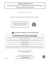
This furnace is manufactured with 2” CPVC vent & intake
couplings. Use transition cement to connect PVC or ABS
pipe, the transition from 2” to 3” should be made as close to
the furnace as possible, and only when the piping is sloped
enough to prevent condensation from collecting.
vent or vent connector, and must not be vented into masonry
chimney. A masonry chimney may be used as a chase or
passage way for approved venting materials providing the
masonry chimney is not also being used to vent products of
combustion. Never common vent this appliance with another
appliance. Never use a vent which is used by a solid fuel
appliance.
Piping may run vertically or horizontally and must be ad-
equately supported to prevent strain on joints, sagging,
separation, and detachment from the furnace. Horizontal
Condensation within the furnace secondary heat exchang-
er and in the vent pipe is a normal occurrence. Vent pipe
must be installed to maintain a minimum 1/4 inch per foot
downward slope toward the furnace to return condensate to
in the intake pipe. This commonly takes place during the
summer months when humid air enters an intake pipe that
runs through a cool basement or other conditioned space.
managing condensation.
T
O
AVOID
BODILY
INJURY
,
FIRE
OR
EXPLOSION
,
SOLVENT
CEMENTS
MUST
BE
KEPT
AWAY
FROM
ALL
IGNITION
SOURCES
(
I
.
E
.,
SPARKS
,
OPEN
FLAMES
,
AND
EXCESSIVE
HEAT
)
AS
THEY
ARE
COMBUSTIBLE
LIQUIDS
.
A
VOID
BREATHING
CEMENT
VAPORS
OR
CONTACT
WITH
SKIN
AND
/
OR
EYES
.
Figure 4

12
TRANSITION NO LESS
PIPING.
°
ACCEPTABLE
NO TRANSITION ON
HORIZONTAL PLANE,
THIS CREATES A
RESTRICTS FLUE
GASES
NOT ACCEPTABLE
Figure 6
Precautions must be taken to prevent condensate from freez-
ing inside the vent pipe. All vent piping exposed to freezing
temperatures must be insulated with 1/2” thick closed cell
foam. Inspect piping for leaks prior to installing insulation.
Consult table 4 to determine what diameter piping is required
for your installation. Lengths shown in table 4 apply to single
pipe & two pipe installations. In a two pipe installation do not
add intake and vent pipe lengths together. Both pipes would
must be within the limits of table 4. It is preferable to up-size
near maximum. This will help avoid nuisance pressure switch
opening caused by prevailing winds & sudden changes in
atmospheric pressure.
123458
2
3 144 137 123 116
2
3 144 137 123 116
123458
3
3
69
93
87
81
63
43
37
73
67
61
49
TABLE 4
The vent pipe outlet is sized to accept 2” pipe. Secure vent
glue. Alternately, a small section of 2” pipe may be glued
in the furnace socket and a rubber coupling installed to
allow removal for future service. Piping should be routed in
a manner to avoid contact with refrigerant lines, metering
devices, condensate drain lines, etc. If necessary, clearances
(Figure 7).
Figure 7
E
DGES
OF
SHEET
METAL
HOLES
MAY
BE
SHARP
. U
SE
GLOVES
AS
A
PRECAUTION
WHEN
REMOVING
HOLE
PLUGS
.
If the furnace is being installed without a combustion air pipe,
guard against blockage.
intake pipe to the air intake coupling using a rubber coupling
supplied with the furnace. The rubber coupling may be omitted
by inverting the intake coupling and gluing pipe directly to it.
Piping may also be glued to the intake coupling in its original
position by using a plastic coupling.
Figure 8

13
Combustion Air
Exhaust
coupling (Figure 8) can be secured directly to the furnace
intake coupling if condensation/rain water is a concern. If
be installed with the arrow pointing up. It should be noted,
the combustion air will actually be moving in a direction op-
condensate disposal location. A loop in the drain tube can
an acceptable method of catching condensation. It must have
proper condensate disposal location. A loop in the drain tube
can serve as a trap.
(Up ow/Horizontal models only)
to be run vertically through the side of the furnace (facing up
in horizontal left). The alternate vent location is the 3” hole
directly in line with the induced draft blower outlet.
When using the horizontal alternate vent conguration, you
must use the RF000142 vent drain kit. See Figures 10 & 11
& follow steps below.
Insert flange. Cut 2 ½” long.RF000142
2 ½”
Vent/Flue Pipe Cuts
Figure 11
T
HE
RUBBER
ELBOW
IS
NOT
DESIGNED
TO
SUPPORT
A
LOAD
. W
HEN
THE
RUBBER
ELBOW
IS
MOUNTED
EXTERNALLY
TO
THE
FURNACE
CABINET
,
EXTREME
CARE
MUST
BE
TAKEN
TO
ADEQUATELY
SUPPORT
FIELD
-
SUPPLIED
VENT
/
FLUE
PIPING
,
AS
DAMAGE
CAN
RESULT
IN
LEAKS
CAUSING
BODILY
INJURY
OR
DEATH
DUE
TO
EXPOSURE
TO
FLUE
GASES
,
INCLUDING
CARBON
MONOXIDE
B
E
SURE
NOT
TO
DAMAGE
INTERNAL
WIRING
OR
OTHER
COMPONENTS
WHEN
REINSTALLING
COUPLING
AND
SCREWS
.
top the furnace.
2. Remove the internal elbow, vent pipe and gasket.
4. Remove the 3” plastic plug (in line with the inducer
outlet) and insert it in the space vacated by removal
of the internal vent pipe.
up, on the draft inducer outlet.

14
coupling. Secure it with gear clamp provided.
7. Use the four self-tapping screws removed in step 1 to
8. Connect drain hose to the uncapped port on the
for drain connection details.
horizontal left side down installation or a vertical installation
using down – venting, the alternate combustion air opening
can be used. A locating dimple is located on the right side of
the furnace cabinet. The locating dimple is 1-7/8” measured
from the front edge of the cabinet in line with the knock out.
from cabinet.
2. Insert the 3” cabinet plug from the drain bag assembly
in the unused combustion air hole.
knockout tool used).
4. Use a knockout tool to create a 3” diameter hole.
furnace cabinet using the self-tapping screws removed
in step 1.
Products of combustion must always be vented outside. A
vent pipe must never terminate in an attic, crawl space, or
any other part of a dwelling. Follow the vent pipe & intake pipe
termination requirements listed below as well as all applicable
local, State and National codes.
All terminations (vent and/or intake) must be located at least
12” above ground level or the anticipated snow level.
All vent terminations (non-direct and direct vent) must
terminate at least 3 feet above any forced air inlet located
The vent termination of a non-direct vent application must
terminate at least 4 feet below, 4 feet horizontally from, or
1 foot above any door, window, or gravity air inlet into any
building.
The vent termination of a direct vent application must
gases may enter a building (door, window, or gravity air inlet).
The vent termination of vent pipe run vertically through a
roof must terminate at least 12” above the roof line (or the
anticipated snow level) and be at least 12” from any vertical
wall (including any anticipated snow build up).
A vent termination shall not terminate over public walkways
or over an area where condensate or vapor could create a
nuisance or hazard or could be detrimental to the operation
of regulators, relief valves, or other equipment.
The combustion air intake termination of a direct vent
application should not terminate in an area which is frequently
dusty or dirty.
Vent & combustion air pipes may terminate vertically through
a roof, or horizontally through an outside wall. The combustion
air intake and vent pipe terminations must be in the same
atmospheric pressure zone. Vertical vent pipe terminations
should be as shown in Figure 14. The penetration of pipes
through the roof must be sealed water tight with proper
Horizontal vent pipe terminations should be as shown in the
and prohibit damage to piping connections, a coupling should
be installed on either side of the wall and solvent cemented
to a length of pipe connecting the two couplings. The length
of pipe should be the wall thickness plus the depth of the
the wall. The wall penetration should be sealed with silicone
caulking material.
12"
Vent/Flue Termination
No Terminations
12"
4'
Vent/Flue Termination
Vent/Flue Termination
<10'
Forced Air
Inlet
&
Vent/Flue Terminations
Grade or Highest
Anticipated
Snow Level
Vent Termination Clearances
Figure 12

15
X-3I
I
12” MIN
HEIGHT
12” MIN TO ROOF OR
Figure 14 - Vertical Termination
STRAIGHT
Horizontal Termination (Single Pipe)
Above Highest Anticipated Snow Level
Figure 16

16
Figure 17
Figure 18
Combustion Air Intake may also be snorkeled
to obtain 12” min ground clearance.
Alternate Vent Termination Above Anticipated Snow Level
Figure 19
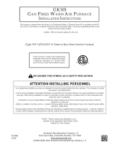
3” MIN
3”MIN
12” M IN SE PA RAT ION
Termination of
If more than one direct vent furnace is to be installed
vertically through a common roof top, maintain the same
minimum clearances between the exhaust vent and air
intake terminations of adjacent units as with the exhaust
vent and air intake terminations of a single unit.
If more than one direct vent furnace is to be installed
horizontally through a common side wall, maintain the
exhaust vent outlets at the same elevation and always
terminate all air intakes at the same elevation.
3” MIN
12” M IN SE PA RAT ION
Refer to the directions provided with the Concentric Vent
Kit or IO-619 for installation specications.

17
Vertical Installation
Horizontal Installation
Allowable Installation Orentation
This kit is to be used with 2” or 3” direct vent systems. The
vent kit must terminate outside the structure and may be
installed with the intake and exhaust pipes located side-
by-side or with one pipe above the other. These kits are
NOT intended for use with single pipe (non-direct vent)
installations.
A condensing gas furnace achieves its high level
combustion to the point where condensation takes place.
The condensate must be collected in the furnace drain trap
and routed to an appropriate drain location in compliance
with local and national codes.
Follow the bullets listed below when installing the drain
concerning furnace drain trap installation and drain hose
hook ups.
• The drain trap supplied with the furnace must be
used.
• The drain trap must be primed at time of installation.
• The drain line between furnace and drain location
must meet local and nation codes.
• The drain line between furnace and drain location
must maintain a 1/4” per foot downward slope toward
the drain.
•
the drain trap supplied with the furnace.
• If the drain line is routed through an area which may
see temperatures near or below freezing, precautions
must be taken to prevent condensate from freezing
within the drain line.
• If an air conditioning coil is installed with the furnace,
a common drain may be used. An open tee must
be installed in the drain line, near the cooling coil, to
This is necessary to prohibit any interference with the
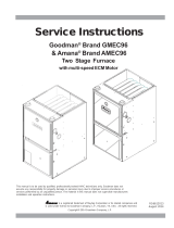
#3
#1 #2
#4
#6
#7 #8
#9
#11
100 Degree
Elbow
Coupling
All furnace models come with a factory installed drain trap.
For vertical installations, the trap will remain in the factory
position. All furnace models installed horizontally require
the trap to be relocated. Many drain hoses have a built–in
grommet which will provide a cabinet seal when installed.
See instructions below for your model and installation
position.

18
in compliance with code requirements. In horizontal
the drain trap to be removed for cleaning. The drain trap
supplied furnace drain, it must be vented. An open tee
must be installed at a height no higher than the bottom
of the furnace collector box to prevent air conditioning
condensate from backing up into the furnace, if the
common drain was blocked.
The trap and factory installed hoses remain as shipped.
The furnace drain may exit either the right or left side of the
diameter holes which can be used interchangeably for
drain and low voltage wiring purposes. If a higher drain exit
shown in Figure 24. Any unused cabinet opening must be
Hose #1
Hose #2
45º
barb-pipe
adapter
45
barb-pipe
adapter
º
Installer selects right or left side drain
and installs this hose accordingly
1.
from the outside of the cabinet (barbed end goes
in the cabinet) through hole in the right side of the
2. Locate the long drain hose #3 and cut at line “A”.
3. Install large end of hose #3 to trap outlet and secure
4.
secure with 1” clamp.
trap.
1.
outside of the cabinet (barbed end goes in the
cabinet) through the hole in the left side of the cabinet
2. Locate the long drain hose #3 and cut at “B” line for a
3. Install large end of hose #3 to trap outlet and secure
4.
secure with 1” clamp.
trap.

19
Hose #11 Hose #2
Minimum 5 ½” clearance is required for the drain trap
beneath the furnace.
1. Remove the clamps from both ends of the drain
hoses.
2. Remove the two screws holding the drain trap to the
blower deck.
3. Remove the trap and two hoses from the blower deck
4. Remove the two plugs from the right side of the
cabinet and install them in the blower deck.
cabinet through the cabinet drain hole nearest the top,
clamp.
6.
end of hose #11 from outside the cabinet in the
bottom drain hole. Install on collector box and secure
with a silver clamp.
7. Use two silver clamps and secure the hoses to drain
trap. The trap outlet faces the front of the furnace.
Secure the trap to the cabinet using two screws
removed in step 2 by inserting the two screws through
the large set of holes in the top mounting tabs of the
trap into the two predrilled holes in the side of the
cabinet.
8.
trap.
Hose #6
Hose #5
Hose #11 Front Cover
Pressure Switch
Tube Location
Minimum 5 ½” clearance is required for the drain trap
beneath the furnace.
*See Front Cover Pressure Switch Tube Location on Figure
27.
1. Remove the clamps from the two drain tubes on the
trap.
2. Remove the two screws holding the drain trap to the
blower deck.
3. Remove the trap and hoses from the blower deck.
4. Remove the two plugs from the left side of the cabinet
and install them in the blower deck.
for a “B” width cabinet.
6. Remove the rubber plug from vent – drain elbow side
port. Place hose #6 on the vent – drain elbow side
port and secure with a silver clamp .
7. Unused vent-drain elbow drip leg port must be sealed
plug removed in step 6 into the unused elbow drain
wrench into the center of the rubber plug will stretch
the plug and allow complete insertion.
8.
9.
drain hole.
secure with two red clamps
11.
side collector box drain port (bottom in horizontal left
position) and install it on right side (top) collector box
drain port.
12. Install the non-grommet end of hose #11 from outside
the cabinet in the upper drain hole. Install on collector
box and secure with a silver clamp.

20
13. Use two silver clamps and secure the hoses to drain
trap. The trap outlet faces the front of the furnace.
Secure the trap to the cabinet using two screws
removed in step 2 by inserting the two screws through
the large set of holes in the top mounting tabs of the
trap into the two pre-drilled holes in the side of the
cabinet.
14.
trap.
Insert flange. Cut 2 ½” long.RF000142
2 ½”
1.
end.
2.
outlet and secure with a red clamp.
3. Insert coupling in hose #2 and secure with a red
clamp.
4.
drain hole.
6.
7. Locate hose #6. Using red clamps, connect between
tubing.
8.
side collector box drain port (bottom in horizontal left
position) and install it on right side (top) collector box
drain port and secure with a red clamp.
9. Install the non-grommet end of hose #11 from outside
the cabinet in the upper drain hole. Install on collector
box and secure with a silver clamp.
Use two silver clamps and secure the hoses to drain
trap. The trap outlet faces the front of the furnace.
Secure the trap to the cabinet using two screws
removed in step 2 by inserting the two screws through
the large set of holes in the top mounting tabs of the
trap.
WARNING
The wiring harness is an integral part of this furnace.
the wiring diagram for wire routings. If any of the original
wire as supplied with the furnace must be replaced, it must
be replaced with wiring material having a temperature
copper conductor.
Before proceeding with electrical connections, ensure that
the supply voltage, frequency, and phase correspond to
the furnace must be NEC Class 1, and must comply with
all applicable codes. The furnace must be electrically
grounded in accordance with local codes or, in their
absence, with the latest edition of The National Electric
Use a separate fused branch electrical circuit containing
properly sized wire, and fuse or circuit breaker. The fuse
or circuit breaker must be sized in accordance with the
rating plate. An electrical disconnect must be provided at
the furnace location.
Connect hot, neutral, and ground wires as shown in the
conduit is not considered a substitute for an actual ground
wire to the unit. For direct vent applications, the cabinet
opening to the junction box must be sealed air tight using
either an UL approved bushing such as Heyco Liquid
Tight or by applying non-reactive UL approved sealant to
bushing.
connections. Line voltage connections can be made
through either the right or left side panel. The furnace is
the junction box located inside the burner compartment. To
make electrical connections through the opposite side of
the furnace, the junction box must be relocated to the other
side of the burner compartment prior to making electrical
connections. To relocate the junction box, follow the steps
shown in the Junction Box Relocation section.
/