Page is loading ...

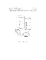
CH1
CH2
SCAN
PLEASE READ CAREFULLY AND SAVE
This manual contains important information about this product’s operation. If you are installing this
product for others, you must leave this manual -or a copy- with the end user.
User’s Manual
2.4 GHZ WIRELESS COLOR WEATHERPROOF
CAMERA KIT WITH REMOTE CONTROL
4919542

Important!
Please read this Manual carefully before installing
or using these units.
WARNING- These units should ONLY be disassembled by an authorized
technician if service is required.
Safety Precautions
For correct and safe operation of this system, it is essential that installers,
end-users and service technicians should follow all safety procedures
outlined in this manual. Specific Warning and Caution statements (and/or
symbols) are marked on the units where needed.
Warning and Caution Statements
”WARNING” indicates a situation where failure to follow proper procedures
can cause personal injury. “CAUTION” indicates a situation where failure
to follow proper procedures can cause damage to the equipment.
This camera is subject to interference from cordless phones, microwaves, and other wireless
devices operating in the 2.4GHz range. Keep the system AT LEAST 10 ft away from the devices
during installation and operation.
ORBYX ELECTRONICS WARRANTY
ORBYX Electronics warrants that this product will be free from defects in materials
and workmanship for a period of one (1) year from the date of purchase. Within
this period, simply take the product and your proof of purchase to any ORBYX
Electronics store or dealer and the product will be repaired without charge for parts
and labour. ORBYX Electronics reserves the right to charge for transportation. Any
product which has been subject to misuse or accidental damage is excluded from
this warranty.
This warranty is only applicable to a product purchased through ORBYX Electronics’
company owned stores and dealers and to a product that is presented for repair in
a country where ORBYX Electronics offers the product for sale. While this warranty
does not confer any legal rights other than those set out above, you may have
additional statutory rights which will vary under the laws of the various countries,
states, province and other governmental entities in which ORBYX Electronics
operates. This warranty is subject to all statutory rights you may have in the
country of purchase.
Limited Warranty/Garantie Limitée
© 2005/2008 ORBYX Electronics. All Rights Reserved.
Imported in Canada for
Importé au Canada pour
Orbyx Electronics,
Concord, Canada, L4K 4M3
Manufactured in China/Fabriqué en Chine
For product support please contact www.orbyxelectronics.com or
1-866-363-3059
Pour le service à la clientèle, veuillez visiter notre site Internet au
www.orbyxelectronics.com ou appelez au 1-866-363-3059

8 1
Disposal
If the camera system no longer functions and can no longer be repaired, it must be disposed of
according to the valid statutory regulations.
Disposal of spent batteries / accumulators
You are required by law (Battery Ordinance) to return all spent batteries
and accumulators. Disposing of spent batteries/accumulators in the
household waste is prohibited! Batteries / accumulators that contain
hazardous substances are marked with the symbols on the side. These
symbols indicate that it is prohibited to dispose of these batteries/
accumulators in the household waste. The abbreviations for the respective
heavy metal are: Cd= cadmium, Hg= mercury, Pb= lead. You can return spent
batteries and accumulators that can no longer be charged, free of charge, to
the collection points in your community, our outlets or everywhere else where
batteries or accumulators are sold.
You thus fulfill the legal requirements and contribute to the protection of our environment!
Troubleshooting
With this camera system, you have purchased a product that reflects the latest state of technology
and is safe to operate. Still there might be problems or malfunctions. At this point, we want to tell you
how to easily remedy possible malfunctions yourself.
Observe the safety notices under all circumstances!
Error Possible Cause
No image and no sound • Camera or monitor are not supplied with
electricity.
• Is the power pack plugged in correctly.
• The distance between the camera and
receiver is too far.
• The supply voltage is too low.
The image/sound is distorted • The range of the system was exceeded.
Shorten the distance.
• There is a strong interference source (e.g.
electric engine, walkie-talkie, etc.) nearby.
• The distance between the camera and the
receiver is too short; this may over steer
the receiver. Extend the distance.
Flickering/running image • Strong spotlight in the cover range of the
camera.
Normal sound, image is too light or dark • Surveillance monitor (TV) is adjusted
wrongly (re-adjust contrast and brightness).
• Strong spotlight in the cover range of the
camera.
White image only on the monitor • The surveillance monitor (TV) is not
correctly adjusted ( brightness controller).
Other repairs as described above may only be performed by an authorized workshop.
Safety and Hazard Notices
Damages caused by non-compliance with this operating manual lead to the
expiration of the warranty! We will not assume any liability for subsequent damages!
We will not assume any liability for damages to items or persons caused by improper
handling or non-compliance with the safety notices! Any warranty claim will be null
and void in such cases.
• This product has left the factory in perfectly safe condition. In order to maintain this status and
ensure safe operation, the user has to observe the safety notices and warnings (“Attention!” and
“Notice!”) contained in this operating manual.
Contents
Safety and Hazard Notices . . . . . . . . . . . . . . . . . . . . . . . . . . . . . . . . . . . . . . . . . . . . . . . . . . . . . . . . 1
FCC/CE Warning. . . . . . . . . . . . . . . . . . . . . . . . . . . . . . . . . . . . . . . . . . . . . . . . . . . . . . . . . . . . . . . . . 3
Parts Included in this System . . . . . . . . . . . . . . . . . . . . . . . . . . . . . . . . . . . . . . . . . . . . . . . . . . . . . . 3
Installing the Camera . . . . . . . . . . . . . . . . . . . . . . . . . . . . . . . . . . . . . . . . . . . . . . . . . . . . . . . . . . . . . 4
Installing the Receiver . . . . . . . . . . . . . . . . . . . . . . . . . . . . . . . . . . . . . . . . . . . . . . . . . . . . . . . . . . . . 5
System Installation. . . . . . . . . . . . . . . . . . . . . . . . . . . . . . . . . . . . . . . . . . . . . . . . . . . . . . . . . . . . . . . 6
Technical Data . . . . . . . . . . . . . . . . . . . . . . . . . . . . . . . . . . . . . . . . . . . . . . . . . . . . . . . . . . . . . . . . . . 7
Maintenance . . . . . . . . . . . . . . . . . . . . . . . . . . . . . . . . . . . . . . . . . . . . . . . . . . . . . . . . . . . . . . . . . . . . 7
Disposal . . . . . . . . . . . . . . . . . . . . . . . . . . . . . . . . . . . . . . . . . . . . . . . . . . . . . . . . . . . . . . . . . . . . . . . 8
Troubleshooting . . . . . . . . . . . . . . . . . . . . . . . . . . . . . . . . . . . . . . . . . . . . . . . . . . . . . . . . . . . . . . . . . 8

2 7
The following symbols need to be observed:
= An exclamation mark in a triangle indicates important notices in these operating
instructions that must be observed under all circumstances.
= A lightning symbol warns of a risk of an electric shock or the impairment of the appliance’s
electric safety.
• You may only use a (120V, 60 Hz) socket of the public supply net for the supply of the power
packs. Never attempt to operate the appliances with a different voltage.
• Make sure that all electric connections and connection cables between the devices of the
camera system as well as the devices to be connected meet the pertaining regulations and are in
conformity with the operating instructions.
• In commercial institutions, make sure you observe the accident prevention regulations of the
commercial trade organization for electric installations.
• In schools, training facilities, hobby and self-help workshops, qualified personnel needs to
supervise the operation of electronic devices.
• Also observe the safety notices and operating instructions of the other appliances connected to
the system.
• Please contact an expert in case you have any doubts about the mode of operation, the safety or
connecting the appliances.
• Do not operate the devices unsupervised.
• When opening the covers or removing parts except where possible by hand, you may expose
live parts. Connections may also be live. Prior to aligning, cleaning, service or repair work or
exchanging parts or modules, you must separate the appliances from all power sources if you
need to open them. Only an expert familiar with the risks and the pertinent regulations may repair
or maintain an open live appliance.
• Never plug-in or unplug the power packs with wet hands.
• Never tug on the power cords of the power packs, use the plug to unplug it from the wall socket.
• Always unplug the power packs from the wall outlet during thunderstorms.
• Make sure that the power cables do not get squashed or damaged by sharp edges when
installing the devices.
• Never replace damaged power cables yourself! In such a case, remove them and take the
devices to a workshop.
Maintenance
The devices are maintenance-free, so never disassemble them. The guarantee becomes void when
you open the appliance. Only clean the outside of the devices with a soft, dry cloth or a brush. Prior to
cleaning, unplug the devices from all voltage sources.
Do not use any carboxylic cleaning agents or petrol, alcohol or similar. These attack the
surfaces of the devices. Besides, the vapors are hazardous to your health and explosive. Do
not use any sharp edged tools, screw drivers, metal brushes or similar for cleaning.
Technical Data
Camera Receiver
Operating voltage 7.5V DC 7.5V DC
Current consumption 300 mA 300 mA
Transmitting frequency 2.4-2.4835Ghz 2.4-2.4835Ghz
Modulation FM
Channels 2 2
Light sensitivity 8-20 Lux
Video output level 1 Vp-p / 75 Ohm
Audio output level, mono 1 Vp-p / 600 Ohm
Audio/Video Connection Jacks AV jack
Picture sensor 1/4” CMOS color
656x492 (NTSC)
Resolution 450 TV lines (horizontal)
Microphone mono
Picture Color
Range approximately 100 m in clear visibility
Operating temperature 14 to 122˚F / -10˚C to 50˚C
Mass approx. (without tripod) 180g 209g
Dimensions (without aerial) L x W x H
2 1/4 x 1 3/4 x 1 3/4”
57 x 44 x 45 (mm)
L x W x H
4 x 3 x 1”
100 x 78 x 24 (mm)
Plug-in power units
Operating voltage 120V / 60Hz 120V / 60Hz
Output voltage 7.5V DC / 300 mA 7.5V DC / 300 mA

6 3
The FCC Wants You to Know
This equipment has been tested and found to comply with the limits for a Class
B digital device, pursuant to Part 15 of the FCC Rules. These limits are designed
to provide reasonable protection against harmful interference in a residential
installation. This equipment generates, uses and can radiate radio frequency energy
and, if not installed and used in accordance with the instructions, may cause harmful interference to
radio communications.
However, there is no guarantee that interference will not occur in a particular installation. If this
equipment does cause harmful interference to radio or television reception, which can be determined
by turning the equipment off and on, the user is encouraged to try to correct the interference by one or
more of the following measures:
• Reorient or relocate the receiving antenna.
• Increase the separation between the equipment and receiver.
• Connect the equipment into an outlet on a circuit different from that to which the receiver is
connected.
• Contact your local electronic store for help.
FCC Information
This device complies with Part 15 of the FCC Rules. Operation is subject to the following two
conditions:
(1) this device may not cause harmful interference, and
(2) this device must accept any interference received, including interference that may cause
undesired operation.
Warning: Changes or modifications to this unit not expressly approved by the party responsible for
compliance could void the user’s authority to operate the equipment.
Parts Included with This System
1. 2.4 GHz Wireless color camera x2
2. 2.4 GHz Wireless receiver x1
3. 7.5V AC/DC Adaptor for the camera x2
4. 7.5V AC/DC Adaptor for the receiver x1
5. A/V Cable x1
6 Remote Control x1
7. Camera bracket x 2
System Installation
When installing the camera, check the reception of the receiver before final installation. Have
someone hold the camera in the area to be monitored. Have another person move the receiver to a
variety of locations throughout the house to check reception. If interference or other problems occur,
refer to the Troubleshooting Guide.
To install the system, follow these steps:
- Select the same channel to be used on both the camera and receiver.
Channel selection on the camera
The camera can be set up in two different optional channels. To
set the channel, use a pointed object, e.g. a ballpoint pen, to select
the desired channel to position on CH1 or CH2. Only one channel
is activated on one camera.
Channel selection on the receiver
The receiver can receive up to two different channels. Detect the available signal and execute auto
scan function. You now have the possibility of selecting a certain channel or monitoring up to two
cameras in scan mode.
A. Single Channel Display
If only one camera is installed
Turn off then turn on the receiver, the receiver will scan the available channels and lock on a
specific camera either camera 1 or camera 2.
B. Two Channel Display
If more than one camera is installed and operate simultaneously
1. Turn off then turn on the receiver, the receiver will detect two channels, and enter into auto
scan mode (5 seconds interval between CH1 & CH2)
2. Select the channel you wish to watch; simply by pressing the channel selection button on
remote control/receiver for desired channel (1st, 2nd press).
3. For auto-scan channel selection with 3rd press to the channel selection button, all 2
channels: CH1, CH2 are displayed for Camera 1, Camera 2 on the TV/monitor at 5 sec
intervals repeatedly.
Notice:
1. The cameras are preset to CH1 and CH2 from factory.
2. While the system is in operation if either camera is not working properly, push scan button on
remote control or channel SEL on receiver to reset the system.
Press CH SEL once for
Channel 1, Camera 1
Receiver Set to
Channel 1
Press CH SEL twice for
Channel 2, Camera 2
Receiver Set to
Channel 2
Camera Set to
Channel 1
Camera Set to
Channel 2

4 5
Installing the Camera
ATTENTION!
Prior to drilling and inserting the screws, make sure that there are no electric cable pipes,
etc. in the wall that may become damaged.
1. Camera Lens
2. 12 pcs IR LED
3. Antenna
4. Power Jack
5. Camera Stand
6. 1 EDS
7. Microphone
8. Channel Switch
9. Power adaptor
Installing and Connecting the Devices
Select a suitable installation site from which you want to monitor the desired object. A suitable
installation site has the following features:
• dry
• as dust-free as possible
• little vibrations
Select an installation site that is not screened off by reinforced concrete walls, mirrors, metal
shelves, etc. There should not be any appliances with strong electric fields close to the sender
and receiver. Any strong electric environment could cause the interference and reduce the
performance
Fastening the wall bracket
• Look for a suitable place for mounting (with a socket
close-by)
• Screw the wall bracket with the supplied screws to a
suitable wall or a suitable platform, use dowels if relevant.
Connecting the Camera
Connect the low voltage plug of the power unit to the voltage supply jack of the camera.
Pay attention to the correct input voltage of 7.5V DC!
• Insert the plug-in power unit into a suitable mains socket.
• The camera is now ready for use.
• good air circulation
• with a power outlet in close vicinity
Installing the Receiver
Install the monitor approx. 1 m above ground (better receiving condition). There must be a power
outlet in proximity to the receiving site.
ATTENTION!
Only place the monitor on rugged and stable surfaces. Sensitive surfaces or surfaces that
dissolve softeners may become damaged. Use a suitable underlay.
1. Antenna
2. Power LED
3. Channel LED
4. Channel SEL
5. Power ON/OFF
Parts of the Remote Control
Remote Control Instruction
1. Press the CH1 button to view
the camera 1 image.
2. Press the CH2 button to view
the camera 2 image.
3. Press the Auto Scan button to
scan two cameras image.
4. Make sure you are within
Infrared valid distance (2m/ 6
feet) and 30 degree receiving
angle from receiver.
Notice:
1. Camera 1 is preset to CH1
2. Camera 2 is preset to CH2
6. DC Power
7. Video Output Jack
8. Audio Output Jack
9. A/V Cable
10. Power adaptor
Channel button
Scan button
Receiver
Camera 1 Camera 2
/