Page is loading ...

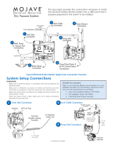
Gas/Liquids/
Solids
From Operatory
Gas
Liquids/Solids
Tank Inlet
Connection Gas
Gas
Tank Outlet
Connection
Pump Exhaust
Connection
Pump Inlet
Connection
Drain/Sewer
Connection
1
2
3
4
MMC Power
& Vacuum Port
Connections
7
6
5
Pump Direct Power &
RJ-45 Control/Status
Connections
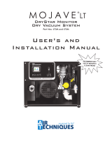
Typical MOJAVE Single Pump Connection Overview
This document provides the connections necessary to install
the MOJAVE system into a utility room that is properly prepared
for the system to be installed.
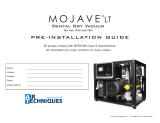
MOJAVE®
Dry Vacuum System
System Setup Connections
Important:
Make sure to install the system in accordance with all local electrical and
plumbing codes.
Make sure to efficiently use space by making connections as short
and direct as possible to meet your particular site requirements.
Make sure that all hose connections are straight and secure without any
sharp bends or kinks.
Since the vacuum hose is rigid, make sure not to stress connections
especially at the pump inlet.
MOJAVE Documentation.
Refer to the following Mojave documentation for more
detailed information on the plumbing, electrical connec-
tions and site requirements as necessary.
• User's and Installation Manual, P/N H5153,
• Pre-Installation Guide, P/N H5187,
• CT20 Dual Tank Product Overview
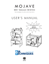
Tank Inlet
Flexible Coupling
Connector
MT10 Tank
Tank Inlet Connection
To Operatory
Suction Line
Inlet
Port
2
3
1
(continue on back)
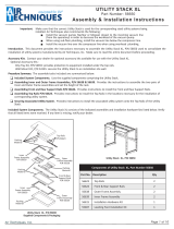
Tank Outlet Connection
1½” ID Hose
P/N 54521
Tank
Outlet
Flexible Coupling
Connector
Pump Inlet Connection
1½” ID
Hose
P/N
54521
Single Pump Tank
Outlet Assembly
P/N H5206
Pump Air
Inlet Filter

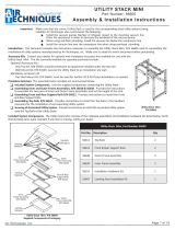
Tank Drain Assembly
Gate Valve
Facility Drain
OR
Open
Drain Pipe
Closed
Vented Drain
Drain/Sewer Connection
MT10 Tank
From 1/4-inch
Vent Condensation
Drain Port
Note:Note: Install 10MM OD Urethane Tubing
(P/N 54509) between the drip leg and
facility sewer drain.
Heat Exhaust Vent Connection
Heat Exchanger
Clamps
P/N 89324
Vent Hose
P/N 56057
Exhaust Vent
Connection
RJ-45
Connector
Electrical Box
Detail
Power Switch with
Circuit Breaker
Pump Direct Power & RJ-45 Control/Status Connections
Supplied 6-Foot BX Cable
from Pump Electrical Box
Black
(208 - 230V)
White
(208 - 230V)
Green
Yellow
(Ground)
Use supplied 10 Foot CAT5e
Network Cable (P/N 419342)
for each Pump to MMC RJ-45
Control/Status Connection
MOJAVE Master Controller (MMC)
IEC AC Power
Receptacle
MMC Power & Vacuum Port Connections
Sample
Vacuum Port
(1/4-inch Elbow)
Tank Outlet
Sample
Vacuum Port
(1/4-inch Elbow)
1/4 inch OD
Urethane Tubing
(P/N 51453)
To
Hospital Grade
NEMA 5-15
Wall Receptacle
Line Cord
(P/N 77243 120V Only)
(P/N 117527 220V Only)
© 2013 Air Techniques, Inc., • P/N H5272, Rev. C •July 2020
Corporate Headquarters
1295 Walt Whitman Road | Melville, New York 11747- 3062, USA
Phone: 1-800-247-8324 | Fax: 1-888-247-8481
www.airtechniques.com
CT20 Tank
(Used with three or four pumps.)
Washout Port
Tank Outlet to
Pump
Tank
Inlet from
Operatory
Master
Controller
Tank Drain
Check
Valve Gate Valve
Multiple Pump System Connection
MT10 Tank
(Used with one or two pumps.)
Dual Pump Tank Outlet
Assembly P/N H5441 with two
check valves H5234 supplied
by MOJAVE Dual System
Installation Kit, P/N MIK2
3 or 4 pumps are connected using a tank outlet manifold
fabricated during site construction with piping supplied by user
and check valves supplied by MOJAVE Triple and Quad System
Installation Kit, P/N MIK4.
From Tank
Outlet
To Pump Air
Inlet Filter
Optional Washout Solenoid Installation
Using the two supplied thread forming screws, install the solenoid onto the
rear of the MT10 Tank.
Install the supplied 3/8 inch tubing from the facility water source to the IN fitting.
Connect the short 3/8 inch tubing between the OUT fitting and the Washout
Fitting on top of the tank.
Washout Solenoid
is Pre-Wired to
the MMC.
OUT to Washout
Fitting
IN from Facility
Water
Flow Direction
3/8-inch
Washout Port
to Washout
Solenoid
4
6
5
7
Exhaust Vent
Assembly
P/N H5302
Flat Side Installed
Facing Up
Clear Hose to
Drain
Check Valve Assembly Side View
Clear Hose
P/N 54521
Note: Not included in
-NHE models
Each pump is wired directly to a dedicated 230V, 20 AMP
(30 AMP for V7) single phase 50/60 Hz circuit using a
disconnect box or circuit breaker panel with approved
ground.
Check
Valve
/