Page is loading ...

A05-15AM-E01_X02 2 - 44
IMPORTANT SAFETY INSTRUCTIONS .....................................................5
1 GETTING STARTED.................................................................................6
1.1 PRECAUTIONS ..................................................................................6
1.2 ELECTRIC SHOCK .............................................................................6
1.3 CLEANING THE TFT LCD MONITOR ...................................................6
1.4 FEDERAL COMMUNICATIONS COMMISSION (FCC) STATEMENT............6
2 INSTALLING THE MONITOR...................................................................7
2.1 UNPACKING......................................................................................7
2.2 MAKING CONNECTIONS.....................................................................7
2.3 REAR COMPONENTS .........................................................................8
2.4 KEY FUNCTION .................................................................................8
2.5 POWER LED ..................................................................................8
3 MENU ........................................................................................................9
3.1 AUTO..............................................................................................9
3.2 COLOR.............................................................................................9
3.3 PICTURE ..........................................................................................9
3.4 FUNCTION ........................................................................................9
3.5 OSD MENU......................................................................................9
3.6 OTHER FUNCTION...........................................................................10
3.7 EXIT..............................................................................................10
4 VARIOUS ................................................................................................10
4.1 MOUNTING THE MONITOR ................................................................10
4.2 TILTING THE DISPLAY......................................................................10
4.3 PACKING THE MONITOR ..................................................................10
5 SPECIFICATIONS : ................................................................................11
5.1 FACTORY PRESET TIMINGS .............................................................12
6 SIGNAL CONNECTOR PIN-OUTS.........................................................12
6.1 15-PIN MINI D-TYPE MALE CONNECTOR ..........................................12
7 TROUBLESHOOTING ............................................................................12
AVVERTENZE............................................................................................15
PRIMA DI INIZIARE ...................................................................................15
7.1 PRECAUZIONI .................................................................................16
7.2 RISCHI ELETTRICI ...........................................................................16

A05-15AM-E01_X02 3 - 44
7.3 PULIZIA DEL PANNELLO LCD ...........................................................16
7.4 COMUNICATO RELATIVO ALLE INTERFERENZE RADIO.........................16
7.5 PRECAUZIONI PER IL CAVO DI ALIMENTAZIONE ..................................17
8 INSTALLAZIONE DEL MONITOR..........................................................17
8.1 DISIMBALLO....................................................................................17
8.2 CONNESSIONE................................................................................17
8.3 LATO POSTERIORE .........................................................................18
8.4 TASTI FUNZIONE .............................................................................18
8.5 LED DI STATO ................................................................................18
9 MENÙ ......................................................................................................19
9.1 AUTO............................................................................................19
9.2 COLORE.........................................................................................19
9.3 IMMAGINE.......................................................................................19
9.4 FUNCTIONI .....................................................................................19
9.5 OSD MENU....................................................................................19
9.6 ALTRE FUNZIONI.............................................................................20
9.7 EXIT..............................................................................................20
10 ULTERIORI INFORMAZIONI................................................................20
10.1 MONTAGGIO DEL MONITOR ..............................................................20
10.2 INCLINAZIONE .................................................................................20
10.3 IMBALLO.........................................................................................20
11 SPECIFICHE : .......................................................................................21
11.1 RISOLUZIONI PREIMPOSTATE IN FABBRICA ........................................22
12 PIEDINATURA DEL CAVO SEGNALE ................................................22
13 PROBLEMI VARI ..................................................................................22
INSTRUCTIONS.........................................................................................25
14 AVANT DE COMMENCER ...................................................................25
14.1 PRECAUTIONS ................................................................................25
14.2 PROPRETE DU PANNEAU LCD .........................................................26
14.3 COMMUNIQUE RELATIF AUX INTERFERENCES RADIO .........................26
14.4 FCC AVERTISSEMENT ....................................................................26
14.5 PRECAUTIONS POUR LE CABLE D'ALIMENTATION ...............................26
15 INSTALLATION DE L'ECRAN .............................................................27
15.1 DEBALLAGE....................................................................................27

A05-15AM-E01_X02 4 - 44
15.2 CONNEXION ....................................................................................27
15.3 COTE POSTERIEUR.........................................................................28
15.4 TOUCHES FONCTION.......................................................................28
15.5 LED D'ETAT....................................................................................28
16 MENÙ ....................................................................................................28
16.1 AUTO............................................................................................28
16.2 COULEUR .......................................................................................28
16.3 IMAGE ............................................................................................29
16.4 FONCTIONNES ................................................................................29
16.5 OSD MENU....................................................................................29
16.6 AUTRES FONCTIONS .......................................................................29
16.7 EXIT..............................................................................................29
17 AUTRES RENSEIGNEMENTS .............................................................30
17.1 ASSEMBLAGE DE L'ECRAN ...............................................................30
17.2 INCLINATION ...................................................................................30
17.3 EMBALLAGE....................................................................................30
18 FONCTIONS DU MICRO REGLAGE ...................................................30
18.1 SAUVEGARDE DES MODES D’AFFICHAGE...........................................30
18.2 REGLAGE PAR L’UTILISATEUR..........................................................30
18.3 REGLAGE PRE-CONFIGURE.............................................................31
18.4 DISPOSITION DES BROCHES DU CONNECTEUR DE SIGNAL VGA........31
18.5 CARACTERISTIQUE D'ECONOMIE D'ENERGIE.....................................31
18.6 DEFINITIONS DU TEMPS ..................................................................31
18.7 SPECIFICATIONS .............................................................................32
WARRANTY CERTIFICATE......................................................................33
CERTIFICATO DI GARANZIA...................................................................35
CERTIFICAT DE GARANTIE.....................................................................37

ENGLISH
A05-15AM-E01_X02 5 - 44
Important Safety Instructions
• Read the Safety Instructions carefully and keep it for later use.
• Be aware of all warnings and instruction signs marked on the products.
• When cleaning, turn off the electrical supply at all times. Never use liquid or aerosol
detergent, use a damp rag instead. For more details, please refer to Pag. 4 “Cleaning
the Monitor.”
• Always keep the product away from heavy moisture.
• Keep this product stable all times. The product may fall causing serious damage.
• Do not clog apertures on the bezels used for ventilation purpose. Do not install this
product in poor ventilated areas. Always keep this product away from all kinds of heat
sources.
• The power source used for this product must match one marked on the product's
label. Please consult your dealer if you have any doubt.
• In order to avoid electric shock, a 3-wire plug with a grounding pin is provided. Do not
use any kind of plug without grounding.
• Do not lay the power cord in a pathway or rest anything heavy on it.
• Do not insert objects or pour liquid into this product through apertures on bezels. It
may touch a high voltage area causing an electric shock or short circuit.
• Do not attempt to repair the product by yourself. It may expose you to electric shock.
Contact a dealer near you for service.
• Do not plug the power cord in under the following circumstances. A qualified field
service electrician is needed.
• When the power cord is damaged or frayed.
• If liquid has been poured into the product.
• If the product has been exposed to rain or heavy moisture.
• If the product can't be adjusted and operated properly by following the operative
instructions. Intent to do more advanced adjustments may result in extensive work
for field service electrician.
• If the product has been dropped or the casting is broken.
• If there is a dramatic change of the performance.
• A proper type of power cord has been selected according to the safety of destination
and must be used to prevent electric shock.

ENGLISH
A05-15AM-E01_X02 6 - 44
1 Getting Started
Congratulations on your purchase of a TFT LCD Color Monitor. This section lists package
contents, features, precautions, as well as cleaning and installation instructions.
I
MPORTANT! PLEASE KEEP THE ORIGINAL BOX AND ALL PACKING MATERIAL FOR FUTURE SHIPPING
NEEDS
.
1.1 Precautions
• Sit at least 18"(45 cm) away from the screen when in use.
• Do not touch the LCD panel with your bare hands. Oil from your skin is difficult to
remove and may damage the screen.
• Do not expose the LCD monitor directly under sunlight or other heat sources. When in
use, the LCD screen should be facing away from light sources to reduce glare.
• It is important to choose a well-ventilated area to place your LCD monitor for adeguate
ventilation. Do not place anything on top of the LCD monitor.
• Ensure the area around the LCD monitor is clean and moisture-free.
• Do not place heavy objects on the power cord, adapter, or signal cables.
• If smoke, abnormal noise, or strange odor occurs, immediately turn the LCD monitor
off and call your dealer. Do not continue using the LCD monitor.
• Do not remove the rear cover by yourself. The display unit contains high-voltage parts
and may expose you to the electric shock. Contact your local dealer if service is
needed.
• When moving, always handle your LCD monitor with care.
• Do not forcefully press down against the LCD display as this will damage the monitor.
1.2 Electric Shock
TO REDUCE THE RISK OF ELECTRIC SHOCK, DO NOT
REMOVE COVER. NO USER-SERVICEABLE PARTS
INSIDE. REFER SERVICING TO QUALIFIED SERVICE
PERSONNEL.
1.3 Cleaning the TFT LCD Monitor
• Wipe the screen gently with a clean camel hairbrush, or a soft, clean, lint-free cloth.
Removing the dust and other particles will prevent your LCD panel from being
scratched.
• Never pour or spray any liquid onto the LCD monitor
• Do not apply pressure to the LCD panel.
1.4 Federal Communications Commission (FCC) Statement
This Equipment has been tested and found to comply with the limits for a class B digital
device, pursuant to Part 15 of the FCC rules. These limits are designed to provide reasonable
protection against harmful interference in a residential installation. This equipment generates,
uses and can radiate radio frequency energy and, if not installed and used in accordance with
the instructions, may cause harmful interference to radio communications. However, there is
no guarantee that interference will not occur in a particular installation. If this equipment does
cause harmful interference to radio or television reception, which can be determined by turning

ENGLISH
A05-15AM-E01_X02 7 - 44
the equipment off and on, the user is encouraged to try to correct the interference by one or
more of the following measures:
• Reorient or relocate the receiving antenna.
• Increase the separation between the equipment and receiver.
•
Connect the equipment into an outlet on a circuit different from that to which the receiver is
connected. - Consult the dealer or an experienced radio/TV technician for help.
2 Installing the Monitor
2.1 Unpacking
Open the shipping cartons and check the contents.
If any items are missing or damaged, contact your dealer immediately.
The package should include the following items:
• TFT color monitor
• User's guide
• Power cord
• Signal cable
• DC power adapter
• Audio cable
2.2 Making Connections
CAUTION:
• Ensure that the power to the monitor, the computer, and other connected devices is off
before making any connections.
• When unplugging the connector, always hold the plug. Never pull on the cord.
1. The monitor, when taken out from the
shipping carton, is in the horizontal
position. Holding the base of the
monitor with one hand and the rear
center of the monitor in the other
hand. Turn the panel up to the vertical
position until you hear the base click
into place.
2. Place the monitor on a flat surface in
a well-ventilated location near your
computer.
3. Connect the signal cable 1 to the
VGA port of the computer. Tighten the two thumbscrews by turning clock wise to
ensure proper grounding.
4. Plug the DC cord of the AC adapter to the power connector 2, then plug the female
end of the AC cord to the AC adapter and the male end to an electrical outlet socket
3.
5. Connect one end of the audio cable to the monitor's Audio Input connector and the
other end to the Audio Output connector of the computer .

ENGLISH
A05-15AM-E01_X02 8 - 44
2.3 Rear Components
2.4 Key Function
POWER: Turns the monitor power ON or OFF,
MENU: Launches the Main menu, selects an
option in the Main menu.
: Select the function and modify the level
AUTO: ............................................................................................................
................................................................................. AUTO ADJUSTEMENT
2.5 POWER LED
Ref Icon⁄Components Description
1
VESA Mounting
Holes
Allow the monitor to be fixed on an UL listed VESA
®
FPMPMI™
compliant mounting device.
2
Signal Cable
Connects the monitor to the VGA port of the computer.
3
Latch
Locks the panel in a secure tilting range.
4
Power Connector
Connects the AC adapter.
5
Audio Input
Connector
Connects the Audio Output connector of the computer.
MODE LED COLOR LED STATUS
POWER OFF OFF OFF
NO SIGNAL / WAIT ORANGE ON
NORMAL GREEN ON

ENGLISH
A05-15AM-E01_X02 9 - 44
3 MENU
Press Menu enter main control menu
Color
Picture
Function
OSD menu
Miscellaneous
Press ◄► button choose and MENU button enter OSD menu
3.1 AUTO
AUTO To calibrate itself according to Input Video, Horizontal
and Vertical position, Fine Tune and Horizontal size
3.2 Color
Press ◄► button choice and MENU button enter OSD menu
Contrast: adjust color contrast
Brightness: adjust brightness
Gamma Correct: adjust screen display
Color Adjust: adjust RGB standard
Color : increase or decrease color intensity
Exit Return to main MENU
3.3 Picture
Press ◄► button choice and MENU button to enter OSD menu
H. Position: adjust display H.Position
V. Position: adjust display V.Position
Sharpness: adjust display Sharpness
Phase: adjust input signal phase
Clock: adjust input signal clock
Exit Return to main MENU
3.4 Function
Press ◄► button choice and MENU button to enter OSD menu
Auto Adjust
Auto Position
Auto Phase
Auto Clock
Auto Color
Exit Return to main MENU
3.5 OSD Menu
Press ◄► button choice and MENU button to enter OSD menu
Language: seven language for choosing
OSD H. Position: adjust OSD H Position

ENGLISH
A05-15AM-E01_X02 10 - 44
OSD V. Position: adjust OSD V. Position
OSD Timer: adjust OSD timer
Translucent: adjust OSD translucent
Exit: Return to main MENU
3.6 Other Function
Press ◄► button choice and MENU button to enter OSD menu
Volume: adjust speaker volume
Exit Return to main MENU
3.7 EXIT
If you choose EXIT , press MENU button to exit main menu
4 Various
4.1 Mounting the monitor
You can install the monitor onto a swing arm or other mounting
fixture that is compliant with the VESA (Video Electronics
Standards Association) standard.
Before mounting the monitor, you must remove the monitor
from its base.
Remove the hinge cover by prying from the bottom part of
the cover.
Remove four screws to detach the monitor from the base.
• To mount the monitor, follow the instructions supplied
with the mounting fixture.
CAUTION: Use an UL listed VESA arm only, or it might result
in malfunction and may cause damage to your monitor.
Please make sure the VESA arm or wall-mounted arm is
adjusted by an authorized LCD agent. Maladjustment can
cause damage to your LCD panel.
4.2 Tilting the Display
Caution:
• Do not touch the screen when you tilt the LCD.
• Do not tilt the LCD beyond the allowed angles when
tilting forward or backward, or the LCD may fall or be
damaged.
• Do not place your fingers on the front of the hinge
arm. Doing so may hurt your fingers when tilting.
For viewing clarity, you can tilt the LCD forward (up to 3
degrees) or backward (up to 25 degrees).
4.3 Packing the Monitor
You need to tilt the monitor to the horizontal position when
packing it into a carton.

ENGLISH
A05-15AM-E01_X02 11 - 44
Follow these steps to pack the monitor:
Disconnect the AC adapter, signal cable, and any cables connected to the monitor.
Tile the panel backward to approx. 25°.
Slide the latch outward and hold it in place 1.
NOTE: Do not tilt the LCD beyond the allowed angles without first sliding the latch to the right.
Doing so may damage the hinge arm.
Then, you can keep on tilting the panel to the horizontal position 2 for packing into a
carton.
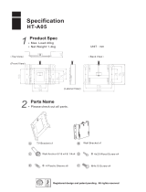
5 Specifications :
Size 15.0" (full 15.0" viewable diagonal area)
Type TFT (Thin Film Transistor), Active Matrix Panel
Pixel Pitch 0,297 x 0.297 mm
Color 16.7 M
Brightness 200 cd/m
2
Contrast 300:1
View Angle +/- 60( H) . 45(UP)/55(DOWN) at CR>10
Response Time <20ms
LCD
Glass surface Anti-Glare & Hard Coat 2H
Input Signal Video RGB Analog
Sync H. V., Separate Sync,
Horizontal Frequency 30-62kHz,
Vertical Frequency 50-75Hz,
Video Sync
Video Bandwidth 80MHz
Audio Speakers 2W x 2
Resolution Primary Mode 1024 x 768
Power Voltage 12V / 3.5A
Connector Input Signal D-SUB (15Pin)
Display Area Full screen 304.1 x 228.1 mm
Temperature 0 ~ +45 Operating
Conditions
Humidity 10% ~ 90%
Temperature -20 ~ + 60 °C Storage
Conditions
Humidity 95%
Physical 365(W) x 175(D) x 365(H)mm
Dimensions
Package 430(W) x 135(D)x 525(H)mm
Net: 3.5Kg.
Weight
Gross: 4.5Kg.
Safety CE, FCC
Low Radiation Yes
Energy Star Yes
Environment Yes
Regulations
Quality ISO 13406-2 Class II
On <30W
Power saving
Off <8W
Customer se
r
If you have any que
s
please contact us a
s
Customer service p
h
Customer service e
-
Website://www.amp
A
mplux Techn
o
7F, #838 Ching K
u
Taiwan.
Tel: 886-3-358-98
8
Fax: 886-3-358-9
8
e-mail: amplux.co
m
http://www.amplu
x

ENGLISH
A05-15AM-E01_X02 12 - 44
5.1 Factory Preset Timings
Timing
Horizontal
Frequency
(KHz)
Vertical
Frequency
(Hz)
Sync
Polarity
(H/V)
VGA 720 X 400 31.467 70.082 - / +
VESA 640 X 480 31.469 59.940 - / -
VESA 640 X 480 37.861 72.809 - / -
VESA 640 X 480 37.500 75.000 - / -
VESA 800 X 600 37.879 60.317 + / +
VESA 800 X 600 48.077 72.188 + / +
VESA 800 X 600 46.875 75.000 + / +
VESA 1024 X 768 48.363 60.004 - / -
VESA 1024 X 768 56.476 70.069 - / -
VESA 1024 X 768 60.023 75.029 + / +
6 Signal Connector Pin-outs
To connect VGA, 8514A or IBM-compatible graphics adapters, use a 15 pin mini D-type male connector.
6.1 15-pin Mini D-type Male Connector
1 Red Video 6 Red Ground 11 Ground
2 Green Video 7 Green Ground 12 Serial Data/I/O
3 Blue Video 8 Blue Ground 13 H. Sync
4 Ground 9 No Connection 14 V. Sync
5 No Connection 10 Sync Ground 15 Serial Clock Input
7 Troubleshooting
CAUTION: Never disassemble the monitor or attempt to service the product yourself. This will
also void warranty. Contact the Atlantis Help Desk Center (see the Warranty Certificate)
• The monitor does not respond after you turn on the system.
Make sure that the monitor is turned on. Turn off the power and check the monitor’s
power cord, AC adapter, and signal cable for proper connection.
• Appear the “ No Input the Signal"
Check the connecting of the audio cable between the monitor and the computer.
• Appear the “ Input Not the Supported"
Input signal are insuperable, refer the “Video Modes”
• The appearance is not at the screen center.

ENGLISH
A05-15AM-E01_X02 13 - 44
Use “AUTO ADJUST” or manually adjust “PHASE” and “CLOCK”, refer the Controls
section.
• The characters on the screen are too dim or too bright
Choose fit color temperature, use “AUTO COLOUR ADJUST or manually adjust “RGB
ADJUSTMENT, refer the Controls section.
• Interference appear at the view of “CLOSE WINDOWS”
Use the “AUTO ADJUST” or manually adjust the values of “PHASE” and “CLOCK”,
refer the Controls section.

FRANCAIS
A05-15MA-E01_X02 32 - 44
18.7 Specifications
Taille 15.0" (full 15.0" viewable diagonal area)
Model TFT (Thin Film Transistor), Active Matrix Panel
Pixel Pitch 0,297 x 0.297 mm
N.bre de couleurs affichées 16.7 M
Luminosité 200 cd/m
2
Contraste 300:1
Angles de vision +/- 60( H) . 45(-)/55(+) at CR>10
Response Time <20ms
Surface visible 304.1 x 228.1 mm
LCD
Surface Anti-Glare & Hard Coat 2H
Input Signal Video RGB Analog
Sync H. V., Separate Sync,
Fréq.Horizz. 30-62kHz,
Fréq. Vert. 50-75Hz,
Video Sync
Bande passante 80MHz
Audio Haut parleur 2W x 2
Resolution Primaire 1024 x 768
Alimentation 12V / 3.5A
Connecteurs Input Signal D-SUB (15Pin)
Temperature 0 ~ +45
Conditions de
jouissance
Humidity 10% ~ 90%
Température -20 ~ + 60 °C Storage
Conditions
Humidité 95%
Produit 365(W) x 175(D) x 365(H)mm
Dimensions
Emballage 430(W) x 135(D)x 525(H)mm
Net: 3.5Kg.
Poids
Lourd 4.5Kg.
Sûreté CE, FCC
Low Radiation Oui
Energy Star Oui
Environnent Oui
Normes
Qualité ISO 13406-2 Class II
On <30W
Economiseurs
d'énergie
Off <8W

A05-15MA-E01_X02 33 - 44
WARRANTY CERTIFICATE
We thank You for your decision to have bought an ATLANTIS LAND® product.
Our society, thank to the quality of its products, offers You an extended guarantee lasting 36
months, both if the product serves for a private use and if it works for a professional one.
This service will be provided to you directly by ATLANTIS LAND®, without asking you for more
interventions, for example brought off by your usual retailer or by others operators.
However please read carefully all guarantee clauses, in order to avoid ungrateful mistakes for the
future eventualities.
If you will provide within 15 days from the purchase to register it on the ATLANTIS LAND®
web site www.atlantis-land.com ,you won’t be asked, if you will need an intervention, the
original proof of purchase (see clause n° 6).
Clauses
The product is warranted for a period of 36 months from the date of purchase.
10. During this period ATLANTIS LAND® will replace the apparatus which will show defects
in conformity to that product’s standard.
11. The replacement will take place without any cost for the costumer.
12. To start the guarantee process the costumer will have to report the defect (by Fax, E-Mail
or Telephone) to the ATLANTIS LAND® Assistance Service, that will provide a new RMA
number.
13. This RMA number will have to be reported, together with all the other information
requested, on the appropriate form, attached to the product or available on the web site
www.atlantis-land.com (Support\Warranty page)
14. This form must be accompanied by a valid proof of purchase (Sale receipt or Invoice ),
this clause is not compulsory if the costumer had previously registered his purchase on
the ATLANTIS LAND® web site.
15. The non conformity to one of the previous points 5 and 6 makes the Guarantee
irrecoverable by the costumer.
16. The product must be returned with its original package intact and complete with all its
accessories.
17. If you return a non original or non intact package the material will travel at your own risk
, and ATLANTIS LAND® doesn’t assume any kind of responsibility about eventual
damages even in case of a transport by ATLANTIS LAND® itself .
18. ATLANTIS LAND® takes back the defective product and replace it with the expedition
to the costumer of a new one.
19. Every ATLANTIS LAND® product is identified by a serial number (S/N) , the
cancellation, even partial, of it bring to the cancellation of the Guarantee.
20. The Guarantee is ineffective even when the damages are due to clear fraud, negligence,
the non conformity with the specifics of the product, modification or tampering.
21. The Guarantee is ineffective also if we find out attempts, succeeded or not, of opening
the apparatus.
22. Moreover damages due to natural phenomena or to extraordinary happenings they are
not included in the Guarantee.
23. Damages due to the connections of the apparatus to tensions which are different from the
ones indicated, or due to sudden changes in the tension of the net to which the
apparatus is connected to, as well as the ones due to any kind of electrical discharge
(lightning, overextensions, electrostatic or inductive discharges ) are not included too.
24. At last damages due to fire or liquid infiltrations are excluded as well.

A05-15MA-E01_X02 34 - 44
25. All the elements that undergo wear and tear as accumulator’s batteries , batteries
themselves , fuses and bulbs even when furnished , cables for the connection or the
feeding and connectors are not included in the Guarantee.
26. Exactly only for the line of UPS products the batteries that are furnished with the
product itself are in Guarantee for 12 months.
27. The external feeders, of every kind of apparatus, are covered by a 12months
Guarantee.
28. Possible updating of the software or of the firmware, revisions or upkeeps are not
covered by the Guarantee too.
29. For each apparatus send for reparation and for which no defects will be found by the
Assistance Service, you will have to pay for the transport (retire and return) and for a
contribution of test that amount to €30. The total sum will be notified to you by ATLANTIS
LAND®, and only the payment through an allowance will make the return of the
apparatus possible.
30. If after 6 months from the request we haven’t received the payment yet ATLANTIS
LAND® will proceed with the selling off of the apparatus without need to inform you of
anything and it will consider the practice as closed.
31. The Guarantee is provided only by ATLANTIS LAND® s.p.a. to its Assistance Center
.Address : Via De Gasperi, 122 – 20017 – Mazzo di Rho (MI) – Phone:
+39.02.939.076.34.
32. Any controversy will be up to the Foro di Milano.

A05-15MA-E01_X02 39 - 44
Demand of assistance Form
Fill all the blanks, attach always a copy of the proof of purchase (Sale Receipt or Invoice),
and add it all to the product for which you are asking for assistance.
RMA (given by ATLANTIS LAND
®
):_____________________________________________________
Defect:
___________________________________________________________________________
_________________________________________________________________________________
_________________________________________________________________________________
Type:
__________________________Serial Number: _____________________________________
For more information call:
____________________________________________________________
Phone:
__________________Fax: __________________E-mail: ____________________________
Address for sending and retiring of the defective product:
Surname:
_________________________________________________________________________
Name:
___________________________________________________________________________
Corporate name (obligatory for the societies)
____________________________________________
Zip code __________________City ____________________________________________________
Street ______________________________________________________n_____________________
Tax Code or VAT Number __________________ _____________________(you must always write it)
I agree with this with all the clauses of Guarantee, paying particular attention to
the restrictive ones, shown by ATLANTIS LAND® for this product.
Date __________________Signature___________________________________________________
Consent for the treatment of information according to law 675/96 art. 11and 12
PRIVACY TUTELAGE
I authorize ATLANTIS LAND
®
to insert my personal information into its data bank, with the only aim to apply the Guarantee to the
product over mentioned and for the future administrative, commercial and statistic management.
At any time I will be allowed to ask , according to law 675/96 art.13, to change or to cancel them or to oppose their use informing of that
ATLANTIS LAND
®
, via De Gasperi, 122 – 20017 – Mazzo di Rho (MI).
Date __________________Signature______________________________________________________________________________
N.B.: The award of the information is facultative, but its lack will prevent ATLANTIS LAND® from starting the Guarantee process
requested.

A05-15MA-E01_X02 44 - 44
HEADQUARTER & EUROPE
A
TLANTIS LAND S.p.A.
Viale De Gasperi, 122
Mazzo di Rho – MI – Italy
info@atlantis-land.com
A
TLANTIS LAND FRANCE
C
ENTRE AMSTERDAM
7,
RUE D’AMSTERDAM
P
ARIS – FRANCE
FAR EAST AND USA SALES:
Atlantis Land
International Sales Office
N° 249 Hsing South Rd.
Taipei – Taiwan
Atlantis Land Technology L.t.d.
3
rd
. Floor, Jonsim Palace
228 Queen’s Road East
Wanchai, Hong Kong
info.hk@atlantis-land.com
/