Electrolux 318201778 User manual

Category
Cookers
Type
User manual

This manual is also suitable for

1
36" GAS RANGE INSTALLATION INSTRUCTIONS
If the information in this manual is not followed exactly, a fire
or explosion may result causing property damage, personal injury or death.
FOR YOUR SAFETY:
Do not store or use gasoline or other flammable vapors and liquids in
the vicinity of this or any other appliance.
WHAT TO DO IF YOU SMELL GAS:
Do not try to light any appliance.
Do not touch any electrical switch; do not use any phone in your building.
Immediately call your gas supplier from a neighbor's phone. Follow the
gas supplier's instructions.
If you cannot reach your gas supplier, call the fire department.
Installation and service must be performed by a qualified installer, service
agency or the gas supplier.
P/N 318201778 (0809) Rev. A
English - pages 1-8; Español - páginas 9-16
Notes - pages 17-19; Wiring Diagram - page 20
Note: Wiring diagram for this model is enclosed in this booklet (see page 20).
Printed in United States
INSTALLATION AND SERVICE MUST BE PERFORMED BY A QUALIFIED INSTALLER.
IMPORTANT: SAVE FOR LOCAL ELECTRICAL INSPECTOR'S USE.
READ AND SAVE THESE INSTRUCTIONS FOR FUTURE REFERENCE.
OBSERVE ALL GOVERNING CODES AND ORDINANCES.
Note: For
appliances
installed in the
state of
Massachusetts
see page 2.
Refer to your
serial plate for
applicable agency
certification
NOTE: 28" (71.1 cm) minimum clearance between the
cooktop and the bottom of the cabinet when the bottom
of wood or metal cabinet is protected by not less than
1/4" (0.64 cm) flame retardant millboard covered with
not less than No. 28 MSG sheet metal, 0.015" (0.4 mm)
stainless steel, 0.024" (0.6 mm) aluminum, or 0.020"
(0.5 mm) copper.
34" (86.4 cm) minimum clearance when the cabinet
is unprotected.
Do not pinch the power supply cord between the range
and the wall.
Do not seal the range to the side cabinets.
A
B
C
D
E
G
F
13" Max.
(33 cm Max.)
24" Min.
(61 cm Min.)
24 1/2" Max.
(62.2 cm Max.)
35 7/8" Min.
(91.1 cm Min.)
See
note
Grounded
Wall Outlet
location
WALL
WALL
If there is a wall:
7" Min.
(17.8 cm Min)
Left side
18" Min.
(45.7 cm Min.)
If there is a wall:
7" Min.
(17.8 cm Min.)
Right side
A. HEIGHT
41 5/8" (105.7 cm) Min.
42 5/8" (108.3 cm) Max.
B. WIDTH
35 7/8"
(91.1 cm)
C. DEPTH TO
FRONT OF RANGE
27 ½"
(69.9 cm)
D. HEIGHT OF
COOKTOP
35 3/4" (90.8 cm) Min.
36 3/4" (93.3 cm) Max.
E. DEPTH WITH
DOOR OPEN
47 3/8"
(120.3 cm)
F. HEIGHT OF
COUNTERTOP
36" (91.4 cm) Standard
35 3/4" (90.8 cm) Min.
G. MINIMUM
CUTOUT WIDTH
36 1/16"
(91.6 cm)
2
36" GAS RANGE INSTALLATION INSTRUCTIONS
IMPORTANT SAFETY
INSTRUCTIONS
Installation of this range must conform with local codes
or, in the absence of local codes, with the National Fuel
Gas Code ANSI Z223.1/NFPA No.54.
When installing in a manufactured (mobile) home,
installation must conform with Manufactured Home
Construction and Safety Standard, title 24CFR, part 3280
[Formerly the Federal Standard for Mobile Home
Construction and Safety, title 24, HUD (part 280)] or,
when such standard is not applicable, the Standard for
Manufactured Home Installation, ANSI Z225.1/NFPA
501A-latest edition, or with CAN/CSA-Z240 MH, or with
local codes .
This range has been design certified by CSA
international. As with any appliance using gas and
generating heat, there are certain safety precautions you
should follow. You will find them in the Use and Care
Guide, read it carefully.
• Be sure your range is installed and grounded
properly by a qualified installer or service
technician.
This range must be electrically grounded in
accordance with local codes or, in their absence,
with the National Electrical Code ANSI/NFPA No.
70—latest edition in the United States or with CSA
standard C22.1, Canadian Electrical Code, Part 1 in
Canada.
Make sure the wall coverings around the range
can withstand the heat generated by the range.
Before installing the range in an area covered
with linoleum or any other synthetic floor
covering, make sure the floor covering can
withstand heat at least 90°F/32°C above room
temperature without shrinking, warping or
discoloring. Do not install the range over carpeting
unless you place an insulating pad or sheet of 1/4" (6.4
mm) thick plywood between the range and carpeting.
Do not obstruct the flow of combustion air at the
oven vent nor around the base or beneath the
lower front panel of the range. Avoid touching the
vent openings or nearby surfaces as they may become
hot while the oven is in operation. This range requires
fresh air for proper burner combustion.
Never leave children alone or
unattended in the area where an appliance is in use.
As children grow, teach them the proper, safe use of all
appliances. Never leave the oven door open when the
range is unattended.
Stepping, leaning or sitting on the
door of this range can result in serious injuries and
can also cause damage to the range.
Do not store items of interest to children in the
cabinets above the range. Children could be seriously
burned climbing on the range to reach items.
To eliminate the need to reach over the surface
units, cabinet storage space above the units
should be avoided.
Adjust surface burner flame size so it does not
extend beyond the edge of the cooking utensil.
Excessive flame is hazardous.
Do not use the oven as a storage space. This
creates a potentially hazardous situation.
Never use your range for warming or heating the
room. Prolonged use of the range without adequate
ventilation can be dangerous.
Do not store or use gasoline or other flammable
vapors and liquids near this or any other
appliance. Explosions or fires could result.
In the event of an electrical power outage, the surface
burners can be lit manually. To light a surface burner,
hold a lit match to the burner head and rapidly turn the
Surface Control knob to Med. Use caution when
lighting surface burners manually.
Remove broiler pan, food and other utensils
before self-cleaning the oven. Wipe up excess
spillage. Follow the cleaning instructions in the Use &
Care Guide.
Unlike the standard gas range, THIS COOKTOP IS
NOT REMOVABLE. Do not attempt to remove the
cooktop.
Special Instructions for appliances installed in the State of
Massachusetts: This appliance can only be installed in the
State of Massachusetts by a Massachusetts licensed
plumber or gas fitter. When using a flexible gas
connector, it must not exceed 3 feet (36 inches) in
length. A "T" handle type manual gas valve must be
installed in the gas supply line to this appliance.
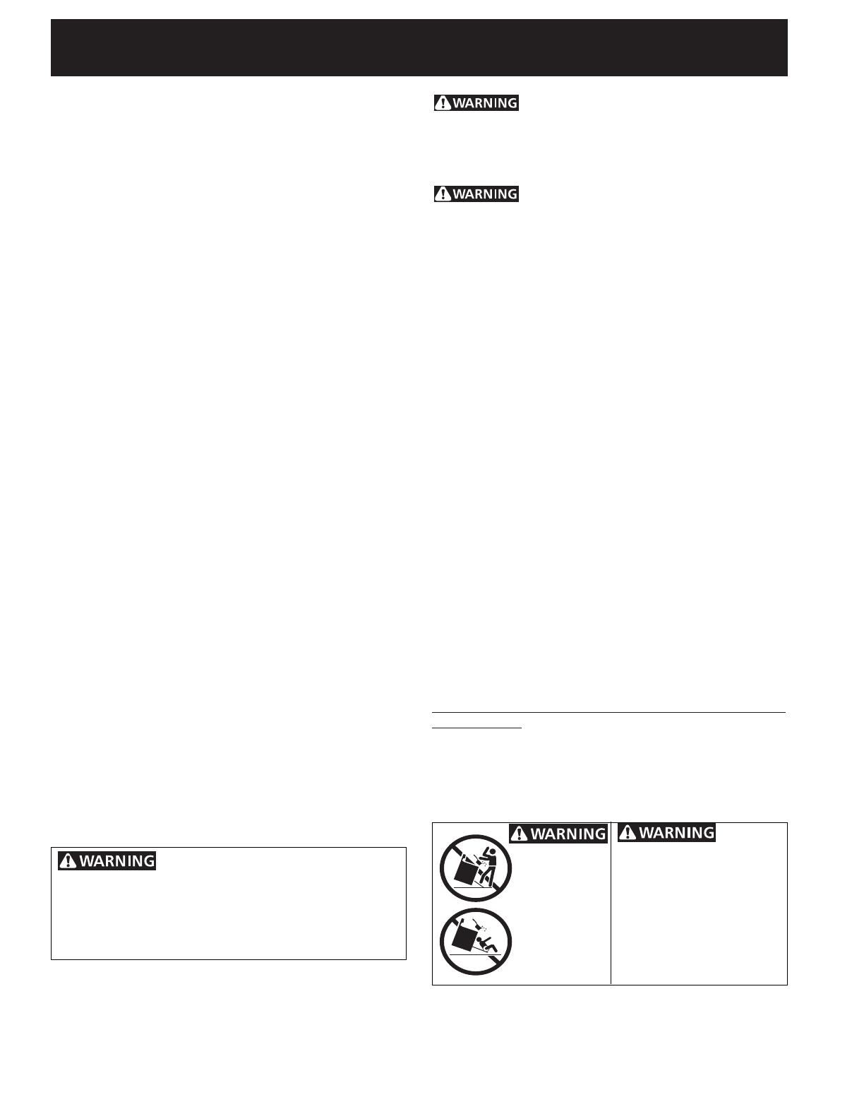
All ranges can
tip.
Injury to
persons could
result.
Install anti-tip
device packed
with range.
To reduce
the risk of tipping of the range,
the range must be secured by
properly installed anti-tip
bracket(s) provided with the
range. To check if the bracket is
installed properly, grasp the top
rear edge of the range and
carefully tilt it forward to make
sure the range is anchored.
Never cover any slots, holes or passages
in the oven bottom or cover an entire rack with materials
such as alminum foil. Doing so blocks air flow through
the oven and may cause carbon monoxide poisoning.
Aluminum foil linings may also trap heat, causing a fire
hazard.
3
36" GAS RANGE INSTALLATION INSTRUCTIONS
1. Model and Serial Number Location
The serial plate is located at back of the appliance.
When ordering parts for or making inquires about your
oven, always be sure to include the model and serial
numbers and a lot number or letter from the serial plate
on your oven.
Figure 1
Serial plate
location
Gas Connector
Important Notes to the Installer
1. Read all instructions contained in these installation
instructions before installing range.
2. Remove all packing material from the oven
compartments before connecting the electrical supply
to the range.
3. Observe all governing codes and ordinances.
4. Be sure to leave these instructions with the consumer.
5. Note: For operation at 2000 ft. elevations above see
level, appliance rating shall be reduced by 4 percent
for each additional 1000 ft.
Important Note to the Consumer
Keep these instructions with your owner's guide for future
reference.
Optional Items Available:
A Stainless Steel Kick Plate
A Black Knob Kit
Those kits can be ordered for purchase through an Electrolux
Service Center at 1-877-4ELECTROLUX (1-877-435-3287).
Preferred Method
Grounding type
wall receptacle
Do not, under any
circumstances, cut,
remove, or bypass
the grounding
prong.
Power supply cord with 3-
prong grounding plug.
Figure 2
2. Electrical Requirements
120 volt, 60 Hertz, properly grounded dedicated circuit
protected by a 15 amp circuit breaker or time delay fuse.
Note: This range is not recommended to be installed
with a Ground Fault Interrupt (GFI).
Do not use an extension cord with this range.
Grounding Instructions
IMPORTANT Please read carefully.
For personal safety, this appliance must be properly
grounded.
The power cord of this appliance is equipped with a 3-
prong (grounding) plug which mates with a standard 3-
prong grounding wall receptacle (see Figure 2) to
minimize the possibility of electric shock hazard from the
appliance.
The wall receptacle and circuit should be checked by a
qualified electrician to make sure the receptacle is
properly grounded.
Where a standard 2-prong wall receptacle is installed, it
is the personal responsibility and obligation of the
consumer to have it replaced by a properly grounded 3-
prong wall receptacle.
Do not, under any circumstances, cut or remove the
third (ground) prong from the power cord.
Disconnect electrical supply cord from
wall receptacle before servicing range.
Electrical Shock Hazard
Electrical ground is required on this appliance.
Do not use the gas supply line for grounding
the appliance.
Failure to do any of the above could result in a
fire, personal injury or electrical shock.
4
36" GAS RANGE INSTALLATION INSTRUCTIONS
3. Gas Supply Installation
When shipped from the factory, this unit is designed to
operate on 4"(10,16 cm) water column (1.0 kPa) Natural
gas manifold pressure. A convertible pressure regulator is
connected to the range manifold and MUST be connected
in series with the gas supply line. The gas connector is
located as shown on figure 1. It is accessible from front of
the range.
For proper operation, the maximum inlet pressure to
the regulator should be no more than 14"(35,56 cm) of
water column pressure (3.5 kPa).
The inlet pressure to the regulator must be at least 1" (.25
kPa) greater than the regulator manifold pressure setting.
The regulator is set for 4"(10,16 cm) water column (1.0
kPa) Natural gas manifold pressure; the inlet pressure must
be at least 5"(12.60 cm) water column (1.25 kPa) Natural
gas. For LP/Propane gas, the regulator must be set for
10"(25,4 cm) water column (2.5 kPa) manifold pressure;
the inlet pressure must be at least 11"(27,9 cm) water
column (2.75 kPa).
The supply line should be equipped with an approved
shutoff valve (see Figure 3 & 4). This valve should be
located in the same room as the range and should be in a
location that allows ease of opening and closing. Do not
Suggested gas connections
All connections must be wrench-tightened
Figure 3
Manual
Shut-off
Valve
Flexible
Connector
90
o
Elbow
Connector
Assemble the flexible connector from the gas supply
pipe to the gas connector in the following order:
1. Manual shut-off valve (not supplied)
2. Flexible connector (not supplied)
3. 1/2" 90
o
Elbow Connector (not supplied)
4. Gas "T" connector (supplied)
Gas "T"
Connector
Connection to Pressure Regulator
The regulator is already installed on the appliance.
Do not make the connection too tight.
The regulator is die cast. Overtightening may crack the
regulator resulting in a gas leak and possible fire or
explosion.
The gas supply line to the shutoff valve should be
1/2"(1,27 cm) or 3/4"(1.9 cm) solid pipe.
The user must know the location of the main shutoff
valve and have easy access to it.
When using flexible gas conduit on the range, allow
sufficient slack to pull the range outside the cutout for
cleaning or servicing.
NOTE: Do not allow the flexible conduit to get pinched
between the wall and the range.
block access to the shutoff valve. The valve is for turning
on or shutting off gas to the appliance. Open the shutoff
valve in the gas supply line. Wait a few minutes for gas to
move through the gas line.
The gas supply between the shutoff valve and the
regulator may be connected by rigid piping or by A.G.A./
C.G.A.-approved flexible metallic union-connected piping
where local codes permit use.
The gas supply piping can be through the side wall of the
right cabinet. The right side cabinet is an ideal location for
the main shutoff valve, if the range is installed within
cabinet storage space
Shutoff Valve -
Open position
to appliance
to gas supply line
Figure 4
Use pipe-joint compound made for use with Natural and
LP/Propane gas to seal all gas connections. If flexible
connectors are used, be certain connectors are not kinked.
The supply line must be equipped with an approved
manual shutoff valve. This valve should be located in the
same room as the range and should be in a location that
allows ease of opening and closing. Do not block access
to the shutoff valve. The valve is for turning on or
shutting off gas to the appliance.
Once regulator is in place, open the shutoff valve in the
gas supply line. Wait a few minutes for gas to move
through the gas line.
Check for leaks. After connecting the range to the gas
supply, check the system for leaks with a manometer. If
a manometer is not available, turn on the gas supply and
use a liquid leak detector (or soap and water) at all
joints and connections to check for leaks. Leaks will be
indicated by bubbles appearing at the connections or
joints.
5
36" GAS RANGE INSTALLATION INSTRUCTIONS
Do not use a flame to check for leaks
from gas connections. Checking for leaks with a flame
may result in a fire or explosion.
All openings in the wall or floor where the range is to be
installed must be sealed.
Tighten all connections if necessary to prevent gas
leakage in the cooktop or supply line.
Disconnect this range and its individual shutoff
valve from the gas supply piping system during any
pressure testing of the system at test pressures greater
than 1/2 psig (3.5 kPa or 14"(35,56 cm) water column).
Isolate the range from the gas supply piping system
by closing its individual manual shutoff valve during any
pressure testing of the gas supply piping system at test
pressures equal to or less than 1/2 psig (3.5 kPa or
14"(35,56 cm) water column).
4. Moving the Appliance for
Servicing and Cleaning
Turn off the range line fuse or circuit breakers at the main
power source, and turn off the manual gas shut-off valve.
Make sure the range is cold. Open the oven door. Lift the
range at the front and slide it out of the cut-out opening
without creating undue strain on the flexible gas conduit.
Make sure not to pinch the flexible gas conduit at the back
of the range when replacing the unit into the cut-out
opening. Close the door and switch on the electrical power
and gas to the range.
5. Range Placement
To eliminate the risk of burns or fire from
reaching over heated surface units, cabinet storage
space located above the range should be avoided. If
cabinet storage space is to be provided, the risk can be
reduced by installing a range hood that projects
horizontally a minimum of 5" (12.7 cm) beyond the
bottom of the cabinet.
Figure 5
Follow instructions for
the type of installation you have
Center
Line of
Range
If range will be installed with a cabinet on both
sides, draw a center line on the floor between the
cabinets (see figure 5). If back of range will not be
flush with the wall (the location of the outlet may not
allow the range to be positioned against the wall), draw
a line on the floor where the back edge of the range will
be. Now install anti-tip bracket (see "Anti-Tip Bracket
Installation", page 8).
If range will be installed with a cabinet on one side
only, move the range into final position. Draw a line on
the floor along the side of the range that is not against
the cabinet. If back of range will not be flush with
the wall (the location of the outlet may not allow the
range to be positioned against the wall), draw a line on
the floor where the back edge of the range will be. Now
install anti-tip bracket (see "Anti-Tip Bracket
Installation", page 8).
If range will not be installed against a cabinet,
move range into final position. Draw a line on the floor
along both sides of the range. If back of range will not
be flush with the wall (the location of the outlet may
not allow the range to be positioned against the wall),
draw a line on the floor where the back edge of the
range will be. Now install anti-tip bracket (see "Anti-Tip
Bracket Installation", page 8).
6
36" GAS RANGE INSTALLATION INSTRUCTIONS
6.2 Check Operation
Refer to the Use and Care Guide and the Electronic Oven
Control Guide packaged with the range for operating
instructions and for care and cleaning of your range.
Remove all packaging from the oven before testing.
1. Burner Bases and Burner Caps
This range is equipped with sealed burners as shown
(Figure 7). All pieces are at their place. Take note where
they are. Remove all packaging material located
under the Dual Surface burner head. Make sure the
burner is properly aligned and leveled. NOTE: There are
no burner adjustments necessary on this range.
2. Turn on Electrical Power and Open Main Shutoff
Gas Valve
3. Check the Igniters
Operation of electric igniters should be checked after
range and supply line connectors have been carefully
checked for leaks and range has been connected to
electric power. To check for proper lighting:
a.Push in and turn a surface burner knob to the LITE
position. All electronic surface ignitors will spark at the
same time. However, only the burner you are turning
on will ignite.
b.The surface burner should light once the flow of gas
reached the surface burner. Each burner should light
within four (4) seconds in normal operation after air
has been purged from supply lines. Visually check that
burner has lit.
c. Once the burner lights, the control knob should be
rotated out of the LITE position.
There are separate ignition devices for each burner. Try each
knob separately until all burner valves have been checked.
Regular Burner
Burner Cap
Fixed Burner Ring
and Burner Base
Dual Surface
Burner
Burner Base
Fixed Burner Ring
Burner Cap
6. Range Installation
1. The back of the range may be installed directly
against the wall.
2. To reduce possible scorching of vertical walls and to
minimize potential fire hazards under abnormal
surface unit use conditions such as high heat or no
pans and to conform to Agency requirements:
- A minimum of 7" (17.8 cm) spacing should be
provided on both sides of the cooktop.
Excessive Weight Hazard
Use 2 or more people to move and install
range.
• Failure to follow this instruction can result in
back or other injury.
6.1 Leveling the Range
1. Install an oven rack in the center of the oven.
2. Place a level on the rack (see Figure 6). Take 2
readings with the level placed diagonally in one
direction and then the other. Level the range, if
necessary, by adjusting the 4 leveling legs with a
wrench (see Figure 11).
3. Slide the range to its final position and double check
for levelness. If the range is not level, pull unit out
and readjust leveling legs, or make sure floor is
level.
Figure 6
Figure 7
7
36" GAS RANGE INSTALLATION INSTRUCTIONS
A
B
5. Adjust the "LOW" Setting of the Dual Burner (see
Figure 7) on the Surface Burner Valve (Figure 9):
Note: On the dual valve the low setting of each portion
(rear portion of bridge burner and the center portion of
bridge burner) should be adjusted individually.
a. Push in and turn control to LITE until the rear portion
of the bridge burner ignites only.
b. Quickly turn knob to LOWEST POSITION.
c. If burner goes out, reset control to OFF.
d. Remove the surface burner control knob.
e. The inner portion of the dual burner flame size can be
increased or decreased by turning screw A (see Figure
9). Use screw B to adjust the flame size of the outer
portion of the dual burner. Turn counterclockwise the
screw to increase flame size. Turn clockwise the
screw to decrease flame size. Adjust flame until you
can quickly turn knob from LITE to LOWEST POSITION
without extinguishing the flame. Flame should be as
small as possible without going out.
Note: Air mixture adjustment is not required on surface
burners.
Figure 9
Figure 8
4. Adjust the "LOW" Setting of Regular Burner (see
figure 7) on the Surface Burner Valves (Figure 8):
a. Push in and turn control to LITE until burner ignites.
b. Quickly turn knob to LOWEST POSITION.
c. If burner goes out, reset control to OFF.
d. Remove the surface burner control knob and
decorative ring.
e. Insert a thin-bladed screwdriver into the hollow valve
stem and engage the slotted screw inside. Flame size
can be increased or decreased by turning the screw.
Turn counterclockwise to increase flame size. Turn
clockwise to decrease flame size. Adjust flame until
you can quickly turn knob from LITE to LOWEST
POSITION without extinguishing the flame. Flame
should be as small as possible without going out.
Note: Air mixture adjustment is not required on surface
burners.
When All Hookups are Complete
Make sure all controls are left in the OFF position.
Before You Call for Service
Read the Before You Call for Service Checklist and
operating instructions in your Use and Care Guide. It
may save you time and expense. The list includes
common occurrences that are not the result of defective
workmanship or materials in this appliance.
Refer to your Use and Care Guide for Electrolux Service
phone numbers, or call 1-877-4ELECTROLUX
(1-877-435-3287).
8
36" GAS RANGE INSTALLATION INSTRUCTIONS
Figure 11
Base of Range
Leveling
Leg
Lower
Raise
Decorative
Leg Screw
A
Center Ligne
Wall
Wall
B
A
B
bracket if template is not available.)
4. Mark on the floor the location of the mounting holes
shown on the template (right and left position). For
easier installation, 3/16" (4.8 mm) diameter pilot
holes 1/2" (1.3 cm) deep can be drilled into the floor.
5. Remove template and place bracket on floor (see
figure 10). Line up holes in bracket with marks on
floor and attach the bracket using the screws
provided. Brackets must be secured to solid floor. If
attaching to concrete floor, first drill 3/16" (4.8 mm)
dia. pilot holes using a masonry drill bit.
6. Level range if necessary, by adjusting the 4 leveling
legs with an adjustable wrench. Loosen the screw
which fixes the decorative leg and lift it to reach the
leveling leg. Turn the leveling leg counterclockwise to
raise the range or clockwise to lower the range (see
Figure 11). Replace the decorative legs at your
convenience.
7. Before sliding the range to its final position; take note
of the serial and model numbers for future reference.
Slide range into place making sure rear leg is trapped
by the bracket. Range may need to be shifted slightly
to one side as it is being pushed back to allow rear
leg to align with bracket.
8. After installation, visually verify
that the anti-tip brackets are
engaged.
Important Safety Warning
To reduce the risk of tipping of the range, the range
must be secured to the floor by the properly installed
anti-tip bracket and screws packed with the range.
These parts are located in a plastic bag in the oven. This
gas range has two brackets. Failure to install the bracket
will allow the range to tip over if excessive weight is
placed on an open door or if a child climbs upon it.
Serious injury might result from spilled hot liquids or from
the range itself.
Follow the instructions below to install the anti-tip
bracket.
If range is ever moved to a different location, the anti-
tip bracket must also be moved and installed with the
range.
Tools Required:
5/16" (8 mm) Nut driver or Flat Head Screwdriver
Adjustable Wrench
Electric Drill
3/16" (4.8 mm) Diameter Drill Bit
3/16" (4.8 mm) Diameter Masonry Drill Bit (if installing
in concrete)
Anti-Tip Bracket Installation
1. The anti-tip bracket must be installed on the right and
left side at back of the range.
2. The anti-tip bracket supports are attached to the floor
at the back. When fastening to the floor, be sure that
screws do not penetrate electrical wiring or plumbing.
The screws provided will work in either wood or
concrete.
3. Unfold paper template and place it flat on the floor
with the back and side edges positioned exactly
where the back and sides of range will be located
when installed. (Use the diagram in figure 10 to locate
Note: Install the anti-tip bracket on the right and left side
Figure 10
AB
36" Range 14 5/16 (36.4 cm) 1 5/8 (4.1 cm)
  • Page 1 1
  • Page 2 2
  • Page 3 3
  • Page 4 4
  • Page 5 5
  • Page 6 6
  • Page 7 7
  • Page 8 8
  • Page 9 9
  • Page 10 10
  • Page 11 11
  • Page 12 12
  • Page 13 13
  • Page 14 14
  • Page 15 15
  • Page 16 16
  • Page 17 17
  • Page 18 18
  • Page 19 19
  • Page 20 20

Electrolux 318201778 User manual

Category
Cookers
Type
User manual
This manual is also suitable for

Ask a question and I''ll find the answer in the document

Finding information in a document is now easier with AI

in other languages