Page is loading ...

OPERATORS MANUAL
TT1200 MPEG2-DVB PROFESSIONAL DECODER,
TANDBERG TELEVISION ASA, Philip Pedersensvei 20, PO Box 322, N-1324 Lysaker, Norway
Tel: +47 67 11 62 00, Fax: +47 67 11 62 01
Installation
and
Operators Manual
7$1'%(5*
R
TT1200 IRD MPEG-2
B
roadcasting
D
igital
V
ideo
TT1200 MPEG2-DVB
PROFESSIONAL DECODER
PAL Version
NTSC Version
SECAM Version
Software version 1.204
VC/MG/ID
And later versions
Article number: 11803677

OPERATORS MANUAL
TT1200 MPEG2-DVB PROFESSIONAL DECODER PAGE 2
TANDBERG TELEVISION ASA, Philip Pedersensvei 20, PO Box 322, N-1324 Lysaker, Norway
Tel: +47 67 11 62 00, Fax: +47 67 11 62 01
CONTENT:
1. INTRODUCTION 5
1.1 DESCRIPTION OF THE TT1200 MPEG2-DVB DECODER 5
1.2 W
HAT’S NEW 6
2. INSTALLING THE UNIT 7
2.1 GENERAL 7
2.2 C
ONNECTION OF EXTERNAL CABLES 7
2.3 B
ASIC SETUP 7
2.3.1 T
UNE THE DEMODULATOR 9
2.3.2 S
ETTING UP THE TV SERVICE:10
2.3.3 S
ETTING UP THE AUDIO 2 AND AUDIO 3 SERVICES 11
2.4 A
DVANCED SETUP 12
2.5 F
AVOURITES 12
2.5.1 S
AVING A CONFIGURATION IN THE ADD MENU 12
2.5.2 S
ELECTING A SAVED CONFIGURATION (SELECT MENU)13
2.5.3 D
ELETING A PROGRAM (PROGRAM DELETE MENU)13
3. TT1200 OUTPUT AND CONNECTOR DESCRIPTION 14
3.1 1
ST
IF 14
3.2 C
ONDITIONAL ACCESS SMART CARD INTERFACE 14
3.2.1 V
IACCESS, CONAX, MADIAGUARD AND NAGRAVISION CA VERSIONS 14
3.2.2 I
RDETO CA SYSTEM 15
3.3 V
IDEO CONNECTORS (BNC) 15
3.4 A
UDIO CONNECTORS 15
3.5 D
ATA CONNECTORS 16
3.5.1 RS 232 C
ONNECTOR 16
3.5.2 RS485 C
ONNECTOR (FUTURE)17
3.5.3 P
IN CONFIGURATION 17
3.6 R
ELAY CONNECTORS 17
3.6.1 ALARM C
ONNECTOR 18
4. THE TT1200 MENU SYSTEM 19
4.1 MENU LAYOUTS 19
4.1.1 N
AVIGATING IN THE EDIT MODE 20
5. MENU DESCRIPTIONS 21
5.1 OVERVIEW OF THE MENU TREE 22
5.2 T
HE STATUS DISPLAY 23
5.2.1 U
NLOCKING THE STATUS DISPLAY 23
5.2.2 L
OCKING THE STATUS DISPLAY 24
5.3 TT1200 M
AIN MENU 24

OPERATORS MANUAL
TT1200 MPEG2-DVB PROFESSIONAL DECODER PAGE 3
TANDBERG TELEVISION ASA, Philip Pedersensvei 20, PO Box 322, N-1324 Lysaker, Norway
Tel: +47 67 11 62 00, Fax: +47 67 11 62 01
5.4 SETUP MENU 24
5.4.1 D
EMODULATOR MENU 25
5.4.2 S
ELECTING TV SERVICE AND AUDIO SERVICES 26
5.4.3 S
ELECTING TV LANGUAGE AND AUDIO LANGUAGES 27
5.4.4 M
ANUAL CONFIGURATION WHEN PSI/SI IS NOT PRESENT 27
5.4.5 A
DVANCED SETUP MENU 28
5.5 S
TATUS MENU 43
5.5.1 A
LARM STATUS 45
5.5.2 D
EMODULATOR STATUS MENU 45
5.5.3 ASI I
NPUT STATUS MENU 46
5.5.4 CA-M
ODULE MENU 46
5.5.5 S
IGNAL STATUS 50
5.5.6 PID
INFO MENU 54
5.6 F
AVOURITES 54
5.6.1 S
ELECT MENU 55
5.6.2 A
DD MENU 55
5.6.3 D
ELETE MENU 56
5.7 P
ROPERTIES 56
6. TECHNICAL SPECIFICATIONS 57
7. APPENDICES 59

OPERATORS MANUAL
TT1200 MPEG2-DVB PROFESSIONAL DECODER PAGE 4
TANDBERG TELEVISION ASA, Philip Pedersensvei 20, PO Box 322, N-1324 Lysaker, Norway
Tel: +47 67 11 62 00, Fax: +47 67 11 62 01
NOTICE
We shall have no liability or responsibility to customer or any other person or entity with respect to any
liability, loss or damage caused or alleged to be caused directly or indirectly by equipment or software
sold or furnished by us, including but not limited to, any interruption of service, loss of business or
anticipatory profits or consequential damages resulting from the use or operation of the equipment or
software.
Read the instructions carefully. No liability will be assumed for any damage caused by improper
installation.
The information in the manual is subject to change without notification. Additional pages may be
inserted in future editions.
The contents of this manual are protected by copyright. No part of this manual may be reproduced or
copied by any means without the permission of the copyright holder.
To prevent electrical shock or fire, do not expose electronic products to rain or moisture and do
not remove covers (or back). If anything fails, leave the repairs to a qualified service technician.

OPERATORS MANUAL
TT1200 MPEG2-DVB PROFESSIONAL DECODER PAGE 5
TANDBERG TELEVISION ASA, Philip Pedersensvei 20, PO Box 322, N-1324 Lysaker, Norway
Tel: +47 67 11 62 00, Fax: +47 67 11 62 01
1. Introduction
1.1 Description of the TT1200 MPEG2-DVB Decoder
The TT1200 is a product in the Tandberg Television ASA growing MPEG2 receiver family. This one
channel 1U unit is designed for professional transcoding of one TV service into PAL, PAL M, SECAM
or NTSC video and one stereo audio pair.
TT1200 draws on more than 10 years of experience in designing high quality and professional
transcoding equipment for the reception of satellite TV channels at cable head-ends.
The decoder occupies 1U in an 19 inch rack and can easily be stacked on top of each other as the
internal fan sustains sufficient air flow from front to back.
The MPEG2 decoder include:
Full range QPSK demodulator 2-30.5Msymb (not on versions with DVB ASI input)
PAL/PAL M/NTSC/SECAM Video output
One stereo audio pair
A low speed RS232 data/remote control port
Alarm relay used for switching purposes
Options available upon request are
ASI output port
ASI input port
Two additional stereo audio pairs
The QPSK input module is capable of receiving a 2-30.5Msymb QPSK modulated signal. It supports
all FEC codes and can supply an LNC Voltage of 13V or 18V. A 22kHz tone can be inserted on the
LNC voltage DC output.
The TV channel comprises an audio and video output pair. The balanced stereo audio output interprets
layer II compressed audio. PAL, SECAM and NTSC video formats are supported. VBI handling
include the following:
Testlines
Teletext (625 lines video)
Wide Screen Signalling (WSS) (625 lines video)
Video Programming System (VPS) (625 lines video)
Ghost Cancelling Reference (GCR) (525 lines video)
Closed Captioning (525 lines video)
Didon Line
Sin(x)/x testline
Frequency sweep
The configurable alarm relay can be used for redundancy switching or other external handling of alarm
events.
Different conditional access systems are supported. Viaccess, Conax, Nagra, Mediaguard, Irdeto, Fixed
Key CA (BISS mode 1) and a Tandberg Television proprietary system are available today.
Control of the decoder is achieved by manoeuvring the menu system available on the front panel LCD
using the four front panel keys. The multi purpose RS232 port gives the user a full remote control
protocol, data output, and software upgrade feature.

OPERATORS MANUAL
TT1200 MPEG2-DVB PROFESSIONAL DECODER PAGE 6
TANDBERG TELEVISION ASA, Philip Pedersensvei 20, PO Box 322, N-1324 Lysaker, Norway
Tel: +47 67 11 62 00, Fax: +47 67 11 62 01
1.2 What’s new
Software versions 1.204VC, 1.204MG and 1.204ID include the following new functionality, with
respect to previous version:
• PAL M video output option (menu selectable)
• Fixed Key descrambling is changed from 64 bit control word to 48 bit control word (BISS mode
1).

OPERATORS MANUAL
TT1200 MPEG2-DVB PROFESSIONAL DECODER PAGE 7
TANDBERG TELEVISION ASA, Philip Pedersensvei 20, PO Box 322, N-1324 Lysaker, Norway
Tel: +47 67 11 62 00, Fax: +47 67 11 62 01
2. Installing the unit
2.1 General
The TT1200 MPEG2-DVB is designed for installation in standard 19 inch rack. Be sure that there is
sufficient space in front of the air inlet and outlet in order to provide the fan powered ventilation of the
unit with fresh air. Do not place the unit close to heat sources
2.2 Connection of external cables
Figure 1. TT1200
Figure 1 shows the decoder with its full configuration. The shaded area is available on request. The rest
comprise the standard configuration of the decoder. Two power supply variants are available, the
common 90-264Volt AC, and the more special purpose -48Volt DC. In case of the DC variant, a
different power connector is used.
Connect the external equipment to the decoder (QPSK signal cable, monitor, Cable network feed, audio
cables, remote control, alarm relay monitor/switch etc). References to the menu system will be written
in boldface fonts e.g. Demod Status.
The TT1200 does not require any external control equipment connected to complete the installation.
Simply connect the QPSK signal cable (F-connector) and the required output signals (video, audio,
data, etc.) to the decoder and plug the 220-110V or 48V power supply on.
2.3 Basic setup
This section describes the basic setup of TT1200. It describes the setup procedure and parameters that
are neccesary in order to get picture and sound at the output when receiving a DVB/MPEG-2 compliant
transport stream with PSI/SI (signalling information).
Basic setup includes tuning the demodulator to the desired satellite frequency and selecting which TV
service to decode. If audio, teletext or subtitling is transmitted in more than one language, the desired
language should be selected. All the setup parameters and submenus are found in the Setup menu. In
addition to the basic setup parameters TT1200 allows various options, such as VBI handling, alarm
handling, PTS handling, RS32 data output and more. These options are found in the Advanced
submenu in the Setup menu.
Because of slightly different functionality between PAL/SECAM and NTSC, the Setup menu appears
slightly different depending on the video format selected in the Video format entry. The Setup menu
when PAL or SECAM is selected is shown in Figure 2. If NTSC or PAL M is selected, the Teletext
and Subtitling menus disappear, and the Caption menu appears.
RS422
RS485
RELAY
RS232
1
st
IF IN
SMARTCARD
VIDEO OUT L AUDIO R
L AUDIO 2 R
ALARM FORMAT
L AUDIO 3 R
SMARTCARD
OUT
ASI
IN

OPERATORS MANUAL
TT1200 MPEG2-DVB PROFESSIONAL DECODER PAGE 8
TANDBERG TELEVISION ASA, Philip Pedersensvei 20, PO Box 322, N-1324 Lysaker, Norway
Tel: +47 67 11 62 00, Fax: +47 67 11 62 01
MAIN MENU
Setup>
Status>
Favourites>
Properties>
SETUP
Demod>*
TV Service>
TV Language>
Video format: PAL
Teletext: Off
Subtitling: On
Audio2 Service>*
Audio2 language>*
Audio3 Service>*
Audio3 language>*
Advanced>
SET:DEMOD
LNC Freq.: 10.000
Sat. Freq: 11.278
Symb. Rate: 24.500
Inner Code: 7/8
LNC Volt: Off
LNC 22kHz: Off
Sptr. inv.: Off
SET:TV LANGUAGE
Lang.: Norwegian
No of pri. Lev: 5
1. pri nor
2. pri swe
...
SET:TV SERVICE
Service id: 601
CNN
Hallmark
Cartoon
SET:AUDIO2 LANGUAGE
Lang.: English
No of pri. Lev: 4
1. pri swe
2. pri nor
...
SET:AUDIO2 SERVICE
Service id: 601
CNN
Hallmark
Cartoon
SET:ADVANCED
System Options>
Output Setup>
Alarm Setup>
RS232 Setup>
Remote Control>
Reset: ALL
Default Setup?
Figure 2 Setup menu for PAL/SECAM video format
All the setup of a TT1200 is done via the arrow keys and the front panel LCD. The LCD is of the 2 line
and 20 character type. The menu representation in this manual gives the impression of a branched tree
left to right. For more details about the use of the front panel display and buttons, please see chapter 4.
The TT1200 menu tree is dynamic, and some menus are present only if certain hardware is installed.
These menus are marked with a *. Menu entries which contains submenus end with
>.

OPERATORS MANUAL
TT1200 MPEG2-DVB PROFESSIONAL DECODER PAGE 9
TANDBERG TELEVISION ASA, Philip Pedersensvei 20, PO Box 322, N-1324 Lysaker, Norway
Tel: +47 67 11 62 00, Fax: +47 67 11 62 01
2.3.1 Tune the demodulator
Note that the demodulator menus are not present in TT1200 units with DVB ASI input.
First of all, the demodulator has to be tuned to the correct satellite frequency. This is done by entering
the parameters in the Demod menu:
1. Enter the LNC frequency (LNC Freq.) of your downconverter, in Giga Hertz. Typical
values are 9.7500, 10.0000GHz, 10.6000 or 11.3000GHz.
2. Enter the satellite signal parameters given for the desired transponder. These are the
satellite frequency (Sat. Freq), symbol rate (Symbol Rate) and inner code (Inner
Code).
3. In the LNC Volt entry, enter the power feed (18 or 13 Volts) required to give the
operation power for correct polarisation, frequency band or amplification depending on
your signal cable configuration. Switch the LNC Volt to Off if this is not required.
4. Use the 22KHz-signal generator (LNC 22kHz) to get the correct frequency band,
polarisation or signal selection depending on your signal cable configuration. If this is not
required leave in Off mode. Note that the 22kHz functionality is HW dependent. Even if
the HW does not support the function, this menu may appear.
5. Set Spectr inv to On if the QPSK signal you want to receive is the inverted spectrum.
Note that this must be done manually i.e. there is no automatic spectrum inversion sensor
implemented.
Note that the demodulator is capable of tuning to a signal that is offset from the LNC frequency by
950MHz to 2150MHz. The symbol rate limitations require the width of a signal to be within 2 Msymb
to 30Msymb. When all parameters are entered, allow the demodulator to search for some seconds. The
result is shown at the top right corner of the display, e.g:
M: 2.4dB.
The M: stands for Margin, and displays the margin, or difference in dB, between the actual input signal
level and a signal level giving Bit Error Ratio (BER) of 2×10
-4
in the viterbi decoder in the
demodulator. In other words, M: 0dB means that the signal level corresponds to a BER of 2×10
4
, a
negative margin value means that the signal level is below the level corresponding to a BER of 2×10
4
.
Correspondingly, a positive value means that the signal level is above this level. If there is No Sync
displayed here after waiting a few seconds, please check the parameters again. If this does not help,
check signal levels and the external cables etc.

OPERATORS MANUAL
TT1200 MPEG2-DVB PROFESSIONAL DECODER PAGE 10
TANDBERG TELEVISION ASA, Philip Pedersensvei 20, PO Box 322, N-1324 Lysaker, Norway
Tel: +47 67 11 62 00, Fax: +47 67 11 62 01
2.3.2 Setting up the TV service:
When the demodulator is receiving OK as explained in the previous section, the TV service parameters
should be set up. Please refer to the menu in Figure 2.
2.3.2.1 Selecting which TV service to be decoded
First you must select which TV service you want to decode. Enter the TV Service menu and find a list
of services that can be seen by using the up and down arrow keys. Select the service you want to see by
pressing the right arrow key. Note that the demodulator must be working OK for you to find this list. If
there is no list of services, check the demodulator status and setup again. Also the service ID can be
typed in manually if this is known, and can thus be configured without the signal being present.
If you have connected a TV monitor to the composite output and speakers to the audio outputs (see
sections 3.3 and 3.4 for detailed description of the video and audio connectors, respectively), you
should now have sound and picture.
For a more detailed description of the TV service menu, please see section 5.4.2.
2.3.2.2 Selecting Language
If more than one language is sent in audio (and video), teletext subtitling, and teletext, the desired
language may be selected in the TV language menu. Please select the preferred language from the
existing predefined priority lists (the priority list can be viewed by scrolling the menu under the selected
language.) If no predefined list applies to the languages of your choice, please select the User def.
entry which gives you the option of manually selecting the language codes for all the components. This
is done by entering the three-letter language code (e.g. nor for norwegian).
You should now have picture and sound with the correct language components.
For a more detailed description of the TV language menu, please see section 5.4.3.
2.3.2.3 Selecting video format
The TT1200 supports PAL, PAL M, SECAM and NTSC composite video. Please enter the Video
format entry and select the video format that is appropriate for your configuration.
The TT1200 automatically detects whether the input signal is 525 lines (NTSC) or 625 lines (PAL or
SECAM) video and outputs the composite video according to this. For example, if the original signal is
625 lines, but Video format is set to NTSC (525 lines), the actual output is 625 lines PAL. But if
there is no appropriate input signal, there will be a black NTSC signal at the composite output in this
case. This means that the Video format entry is used for the following two purposes:
1. Select between PAL and SECAM output for a 625 lines video signal (the menu also includes a
PAL CN option, for future use), and between NTSC and PAL M for 525 lines video.
2. Select between 525 lines and 625 lines video format for black video output when no appropriate
input signal is available.
2.3.2.4 Enable or disable subtitling – PAL or SECAM
The Subtitling entry is used to enable or disable subtitling. Note that subtitling is only available for
PAL or SECAM video, and that this menu entry is only active if PAL or SECAM is selected in the
Video format menu. TT1200 supports two types of subtitling:

OPERATORS MANUAL
TT1200 MPEG2-DVB PROFESSIONAL DECODER PAGE 11
TANDBERG TELEVISION ASA, Philip Pedersensvei 20, PO Box 322, N-1324 Lysaker, Norway
Tel: +47 67 11 62 00, Fax: +47 67 11 62 01
• Teletext Subtitling. Based on subtitling information carried in a specified teletext page. If present,
the decoder will find information about the subtitling page and its language in descriptors in the
transport stream signalling. If Subtitling is set to TTX.sub, the text in the specified subtitling
page is keyed into the video picture.
• DVB Subtitling. A bitmap based subtitling system. Due to the bitmaps, the system can easily
display letters in various fonts and colors. One of the key advantage is the ease by which “special
characters” such as thos found in the Asian languges can be displayed. The subtiling information is
carried by a single PID. The DVB Subtitling SW is based on ETS 300 743. For DVB subtitling the
Subtitling parameter should be set to DVB.
2.3.2.5 Enable or disable teletext – PAL or SECAM
The Teletext entry is used to enable or disable teletext in the composite video signal. Note that teletext
is only available for PAL or SECAM video, and that this menu entry is only active if PAL or SECAM
is selected in the Video format menu. If the transport stream contains teletext for the current TV
service and Teletext is set to On, the teletext information will be inserted in the Vertical Blanking
Interval (VBI) of the video signal, and may be viewed on a TV set with teletext capabilities.
2.3.2.6 Enable or disable closed captioning – NTSC or PAL M
The Captioning entry is used to enable or disable closed captioning. Note that closed captioning is only
available for NTSC and PAL M video, and that this menu entry is only active if NTSC or PAL M is
selected in the Video format menu. If the transport stream contains closed captioning information, this
will be inserted in line 21 in odd fields, if enabled. The inserted closed captioning information may be
in one of the following formats; ATSC, C-Cube or DiviCom.
2.3.3 Setting up the Audio 2 and Audio 3 services
TT1200 may optionally be delivered with two additional audio channels, called Audio 2 and Audio 3.
The shaded area in Figure 1 shows the additional connectors on units with Audio 2 and Audio 3. This
section describes how to set up these audio channels. If you do not have additional audio channels, you
may skip this section.
The explanation below is given for Audio 2. The exact same procedure applies for Audio 3.
2.3.3.1 Selecting Audio 2 service
In the same manner as for the TV service, you must first select which audio service you want to decode.
Enter the Audio2 Service menu and find a list of services that can be seen by using the up and down
arrow keys. Select the service you want to see by pressing the right arrow key. Note that the
demodulator must be working OK for you to find this list. If there is no list of services, check the
demodulator status and setup again. Also the service ID can be typed in manually if this is known, and
can thus be configured without the signal being present.
If you have connected speakers to the audio outputs (see section 3.4 for detailed description of the
audio connectors), you should now have sound on the Audio 2 outputs.
2.3.3.2 Setting up the Audio 2 language
If the service contains more than one language component, the desired language may be selected in the
Audio2 language menu. Please select the preferred language from the existing predefined priority
lists (the priority list can be viewed by scrolling the menu under the selected language.) If no predefined

OPERATORS MANUAL
TT1200 MPEG2-DVB PROFESSIONAL DECODER PAGE 12
TANDBERG TELEVISION ASA, Philip Pedersensvei 20, PO Box 322, N-1324 Lysaker, Norway
Tel: +47 67 11 62 00, Fax: +47 67 11 62 01
list applies to the languages of your choice, please select the User def. entry which gives you the
option of manually selecting the language codes for all the components. This is done by entering the
three-letter language code (e.g. nor for norwegian).
You should now have sound with the correct language components on the Audio 2 output.
2.4 Advanced setup
The TT1200 offers a variety of options such as flexible VBI handling, alarm handling, data output and
more. These options are configured in the Advanced menu. Please see section 5.4.5 for a detailed
description of the options in the Advanced menu.
2.5 Favourites
The TT1200 is equipped with a feature of remembering 10 different configurations of satellite signal
parameters, Service Id’s and language selections associated with the current setup. It is possible to save
configuration or select a previously saved configuration.
MAIN MENU
Setup>
Status>
Favourites>
Properties>
FAVOURITES
Select>
Add>
Delete>
FAV:ADD
0:Astra
1:Telenor
...
FAV:SELECT
0:Astra
1:Telenor
...
FAV:DELETE
0:Astra
1:Telenor
...
Figure 3 Favourites menu
Note that the Favourites menu is only active when PSI is On.
2.5.1 Saving a configuration in the Add menu
When you have completed setup of a TV service you can save the current configuration by entering the
Add menu. You will now be allowed to enter a program name. If available, the Network name of the
current transport stream is displayed as a proposal for the program name. The name may be edited by
using the keypad. When the user has entered a program name he must leave the edit function with the
left or right arrow. He will now be asked if he wants to store the changes. By pressing the Right arrow
the operator acknowledges to save the new entry, Left arrow cancels the save operation. Note that the
following parameters are saved:
• Satellite parameters for the current transport stream

OPERATORS MANUAL
TT1200 MPEG2-DVB PROFESSIONAL DECODER PAGE 13
TANDBERG TELEVISION ASA, Philip Pedersensvei 20, PO Box 322, N-1324 Lysaker, Norway
Tel: +47 67 11 62 00, Fax: +47 67 11 62 01
• Service ID for the current service (if Audio2 and Audio3 services are selected, their service Ids are
saved as well).
• Language selections for both audio and video services.
It is possible to save up to 10 configurations in your Favourites list. For each new service, just
configure the TT1200 to receive the desired service and repeat the Add procedure.
2.5.2 Selecting a saved configuration (Select menu)
To select an earlier saved service, just enter the Select entry in the Favourites menu and select a
service from the scrollable list by pressing Right key. This action will retune the demodulator and
select the saved TV service and if present, the saved Audio2 and Audio3 services. The currently
selected program is shown with a marker in front of the program number.
2.5.3 Deleting a program (Program Delete menu)
To delete an entry from the program list you use the Delete menu. When you choose one of the entries
in the list you will be asked if you realy want to erase that entry or not. When pressing the Right arrow
(Yes) the entry will be deleted. If you press the Left arrow (No) nothing will happen.

OPERATORS MANUAL
TT1200 MPEG2-DVB PROFESSIONAL DECODER PAGE 14
TANDBERG TELEVISION ASA, Philip Pedersensvei 20, PO Box 322, N-1324 Lysaker, Norway
Tel: +47 67 11 62 00, Fax: +47 67 11 62 01
3. TT1200 Output and connector description
3.1 1
st
IF
The 1
st
IF input is a 75 Ohm F connector. The demodulator takes both Ku-band and C-band, and has an
input frequency range from 950MHz to 2150MHz (true or inverted spectrum). The symbol rate range is
from 2Mbaud to 30.5Mbaud.
3.2 Conditional Access Smart Card Interface
In order to support different encryptions of MPEG streams, conditional access is implemented to be
able to decrypt the streams in the decoder. However, the implementation and solution varies between
the different Conditional Access vendors.
Generally, in order to support Conditional Access in any system, the PSI option in the decoder have to
be enabled. This makes the decoder able to receive the data streams which carries the information that
makes the decryption possible.
On T1200 hardware version B1 and higher, there are two slots for smart card readers. Which one to use
depends on what CA system is used, please refer to Figure 4. Note that in the case of Irdeto CA, an
additional CAM interface module and Irdeto PCMCIA CAM module must be installed.
3.2.1 Viaccess, Conax, Madiaguard and Nagravision CA versions
The system is based on using a smart card in the
smart card reader at the bottom right. The smart
card is to be inserted with the “micro-chip-side”
pointing upwards in the smart card slot, as shown
in Figure 5.
In these versions of TT1200, there is a blind plate
over the Irdeto CA smart card reader.
Figure 5 TT1200 smart card interface
SM ARTCARD
Figure 4 Position of smart card readers
RS422
RS485
RELAY
RS232
1
st
IF IN
SMARTCARD
VIDEO OUT L AUDIO R
L AUDIO 2 R
ALARM FORMAT
L AUDIO 3 R
SMARTCARD
OUT
DVB ASI
Irdeto CA
Viaccess
Mediaguard
Conax
Nagravisio

OPERATORS MANUAL
TT1200 MPEG2-DVB PROFESSIONAL DECODER PAGE 15
TANDBERG TELEVISION ASA, Philip Pedersensvei 20, PO Box 322, N-1324 Lysaker, Norway
Tel: +47 67 11 62 00, Fax: +47 67 11 62 01
3.2.2 Irdeto CA system
The Irdeto CA system requires an additional CAM interface module and Irdeto PCMCIA CAM module
to be installed. When this is the case, the upper smart card reader is used, with the chip side of the
Irdeto smart card pointing downwards.
The CA module from IRDETO is inserted by first removing the top lid of the decoder by unscrewing
the phillips screws. The CA interface is present on the card located above the main circuit board. The
CA module is inserted into the CA interface by simply sliding it gently into the slot. Reassemble the
unit by screwing the top lid back on. In order to be able to descramble a IRDETO CA signal, a smart
card can now be inserted face down in the upper smart card reader, as indicated by the arrow below the
smart card slot.
3.3 Video Connectors (BNC)
PAL Testlines in VBI, (lines 17,18 or 19,20)
Teletext (EBU), transparent insertion in VBI
Teletext (EBU), subtitling output on video if enabled.
Wide Screen Signalling (WSS) insertion in VBI
Video Programming System (VPS) insertion in VBI
SECAM Testlines in VBI, (lines 17,18 or 19,20)
Teletext, transparent insertion in VBI
Teletext subtitling output on video if enabled.
Wide Screen Signalling (WSS) insertion in VBI
Video Programming System (VPS) insertion in VBI
NTSC Testlines in VBI (line 17)
Closed Caption
Ghost Cancelling Reference (GCR) in VBI
There is a 15Mbit video rate constraint that apply. The decoding is performed on Main Profile Main
Level (MP@ML), which is the standard for cable headend feeds of today.
When the decoder is not receiving any MPEG information, the video output is black (i.e black signal)
with test-lines in VBI (if enabled). The video output can also be DC when alarm mode is set to DC.
3.4 Audio Connectors
Analogue stereo sound output, balanced (mini XLR):
Stereo, mono or dual tone
The Audio output decodes Layer 2 coded streams with rates from 32Kbits to 384Kbit.
The operator can tailor the audio output to suit the external equipment present. This is done by
configuring the modulator and sound level controls. The modulator control allows the operator to
output the appropriate format to the external equipment regardless of the coding (stereo, mono, dual).
The connectors are of type Mini-XLR. Depending on the external equipment, the outputs can be used as
balanced or unbalanced. Figure 6. Pinout for the audio connectors shows the different connections to
achieve the different outputs.
The AUDIO connector pair is related to the video output of the TV-channel.

OPERATORS MANUAL
TT1200 MPEG2-DVB PROFESSIONAL DECODER PAGE 16
TANDBERG TELEVISION ASA, Philip Pedersensvei 20, PO Box 322, N-1324 Lysaker, Norway
Tel: +47 67 11 62 00, Fax: +47 67 11 62 01
If only MONO output is required, this can be selected in the front panel display menu, see paragraph
5.4.5.2.2 Audio setup menu.
3.5 Data connectors
3.5.1 RS 232 Connector
The RS232 connector is multipurpose and is switchable between:
• general purpose data
• remote control
• software upgrade port
The configuration menu for this port is found in the RS232 setup menu under the Setup ⇒
Advanced menu. When the output is configured to LSData, the decoder will still be able to receive
software upgrades and remote control port configuration messages. For further information see Sections
3.5.1.1 Remote Control and 5.4.5.4.2 Low Speed Data Menu. The pin configuration is shown in Figure
7 Pin configuration.
3.5.1.1 Remote Control
The TT1200 may be controlled remotely. Remote control configuration is done in the Remote
Control menu in the Advanced setup menu. The Remote Control feature enables the user to
control all parameters and features of the TT1200 from a PC through a RS232 Communication cable.
There are two remote control protocols available:
Tandberg Television RS232 remote control, which is described in the following documents:
• External decoder control protocol (RS232) , protocol definition
• Remote control (RS232) TT1200 mk3, parameter definition
Left
Right
SL+
GND
SR+
GND
Left
Right
SL+
GND
SR+
GND
SL-
SR-
1
2
3
Unbalanced audio equipment
(STEREO)
Balanced audio equipment
(STEREO)
Left
Right
SL+
GND
SR+
GND
1
2
3
1 K
1 K
GND
S+
Unbalanced audio equipment
(
STEREO AND MONO
)
STEREO
MONO
Figure 6. Pinout for the audio connectors

OPERATORS MANUAL
TT1200 MPEG2-DVB PROFESSIONAL DECODER PAGE 17
TANDBERG TELEVISION ASA, Philip Pedersensvei 20, PO Box 322, N-1324 Lysaker, Norway
Tel: +47 67 11 62 00, Fax: +47 67 11 62 01
Default baud rate for the communication link is 38400, and is programmable.
The other communication parameters are as follows:
• Parity: off
• Databits: 8
• Stopbit: 1
These parameters are not programmable.
RCDS (RS485). This is a customer specific protocol.
3.5.2 RS485 Connector
RS485 asynchronous data output is switchable between:
• general purpose data
• software upgrade port
• remote control (multi-drop)
Note that software drivers are not implemented for this connector. This will be developed in the future.
3.5.3 Pin configuration
The pin configuration for the data ports is shown in the figure below.
1
6
5
9
GND
TXD -
RXD +
TXD +
RXD -
RS485
Figure 7 Pin configuration
3.6 Relay Connectors
TT1200 has a relay as default. one for alarm signalling , see below. The pin configuration is shown in
Figure 8.
Figure 8 The alarm relay pinning
1
6
5
9
GND
RXD in
TXD out
RTS out
CTS in
RS232
1
5
6
ALARM
9
The figure shows the situation
when there are no alarms in the
system.

OPERATORS MANUAL
TT1200 MPEG2-DVB PROFESSIONAL DECODER PAGE 18
TANDBERG TELEVISION ASA, Philip Pedersensvei 20, PO Box 322, N-1324 Lysaker, Norway
Tel: +47 67 11 62 00, Fax: +47 67 11 62 01
3.6.1 ALARM Connector
If an alarm condition occurs, the alarm relay will be activated after a delay specified in the System
options ⇒ Alarm delay menu entry. The pinning of the connector is given in
Figure 8. If an alarm occours, pin no. 8 will be activated.
The TT1200 handles various status messages from different parts of the system. The current overall
status of the decoder can be directly read from the ‘sleep display’. A more detailed list of possible
alarm conditions can be found in the Advanced ⇒ Status Setup menu. The different status
messages are configurable to represent an alarm condition, a warning or a no-condition, see section
5.4.5.3. If one of the currently present status messages represent an Alarm condition, the alarm relay
will be set.

OPERATORS MANUAL
TT1200 MPEG2-DVB PROFESSIONAL DECODER PAGE 19
TANDBERG TELEVISION ASA, Philip Pedersensvei 20, PO Box 322, N-1324 Lysaker, Norway
Tel: +47 67 11 62 00, Fax: +47 67 11 62 01
4. The TT1200 Menu System
4.1 Menu Layouts
The LCD display on the front panel always displays the current menu. The first line of the display is
reserved for the current menu’s title. The next line display selectable menu items, as shown in Figure 9.
0$,10(180G%
66HWX
S
!
First line:
Title Area
Selectable
Item
Cursor
Scrollbar
indicators
Figure 9 Menu layout
The two arrows at the rightmost position of the LCD display indicate that the current menu has more
than one item. If the
arrow is visible, the list of items continues above the visible item, and if the
arrow is visible, the list of items continues below the visible item. Menu entries containing submenus
end with
>. The TT1200 menu tree is dynamic, and some menus are present only if certain hardware is
installed or if certain menus are configured a specific way. These menus are marked with a *.
The (sub)menus are made up of a sensible combination of types of items which may differ. The
TT1200 has 3 types of menu items. These are:
Sub-menu entries
An item that point to an available sub-menu in the menu hierarchy.
Non-editable items
Provides the user with information about the configuration and status of the TT1200.
Editable items
Allows the user to control a specific functionality of the TT1200.
In general, an item is found by scrolling through menus with the up/down keypad. When the desired
item appears on the display below the title bar, the item can simply be selected by pressing the right
keypad.
• If the item is a sub-menu entry, a new list of items will immediately be available. With the cursor
positioned to the left of any item in the current menu, the previous menu can be accessed at any time
by pressing the left key.
• If the item is a non-editable item, no action will be taken when selected.
• If the item is editable, the menu system enters the edit mode and a parameter can be set by selecting
a predefined value or entering a value/text in a numeric/alphanumeric field. The value of this field is
displayed at the rightmost position of the item’s menu line as shown in Figure 10. A detailed
description of how to navigate in the edit mode is given in Section 4.1.1.
6(7'(02'0G%
6DWIUH
T
Selectable
Item
Figure 10 Menu with parameter item.

OPERATORS MANUAL
TT1200 MPEG2-DVB PROFESSIONAL DECODER PAGE 20
TANDBERG TELEVISION ASA, Philip Pedersensvei 20, PO Box 322, N-1324 Lysaker, Norway
Tel: +47 67 11 62 00, Fax: +47 67 11 62 01
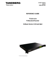
4.1.1 Navigating in the edit mode
Increment Value
Position Cursor
Position cursor
Decrement Value
Figure 11 The navigation keypads.
By pressing the right keypad the editable menu item at the menu system enters edit mode. In edit mode,
the cursor moves into the field displaying a decimal value, a hexadecimal value or a text string. The
keypad command mapping changes to :
Ì
If the selected item is a editable field, the cursor moves to the character left of the current
character. If the current digit is the leftmost character then the menu system leaves the edit
mode.
Í
If the selected item is a editable field, the cursor moves to the digit right of the current
character. If the current character is the rightmost character then the menu system leaves the
edit mode and the new entry is accepted.
Î
If the selected item is a numeric field, the digit under the cursor is incremented by one. For text
fields the next valid alphanumeric value is displayed.
Ï
If the selected item is a numeric field, the digit under the cursor is decrement by one. For text
fields the previous valid alphanumeric value is displayed.
Example for editing the Satellite frequency is given in Figure 12 below:
Current cursor
position
Value decremented
Value incremented
Cursor moved one left
Cursor moved one ri
g
ht
Figure 12 Example of editing numbers
/