Page is loading ...

1
iMarc
™
DSL 9720 CSU/DSU
Installation Instructions
Document Number 9720-A2-GN10-10
May 2003
Contents
iMarc DSL CSU/DSU Overview .................................................................... 2
Upgrading a Unit to Advanced SLM Feature Set .......................................... 3
Product Documentation Online ..................................................................... 3
Package Checklist ........................................................................................ 3
Wiring and Cables You May Need ................................................................ 4
Installing the CSU/DSU ................................................................................ 5
Power-On ...................................................................................................... 10
Status LEDs .................................................................................................. 11
Troubleshooting ............................................................................................ 12
Configuration Setup ...................................................................................... 13
Verifying that Self-Test Passed ..................................................................... 14
Menu Navigation ........................................................................................... 15
Menu Hierarchy ............................................................................................ 15
Using the Easy Install Screen ....................................................................... 18
Completing Setup From the NOC ................................................................. 20
Cables and Connectors ................................................................................ 22
iMarc DSL 9720 CSU/DSU Technical Specifications .................................... 28
Important Safety Instructions ........................................................................ 29
Government Requirements ........................................................................... 30
Warranty, Sales, Service, and Training Information ...................................... 31
NOTE:
In this document, CSU/DSU refers to the line termination capability of the DSL
endpoint, and does not imply association with traditional T1 or DDS equipment.
NOTE: The FrameSaver
®
product line has been
renamed to iMarc.

2
iMarc DSL CSU/DSU Overview
The iMarc
™
DSL (Digital Subscriber Line) CSU/DSU is a component in the iMarc
system. This system allows you to perform end-to-end service level management
across a hybrid DSL/Frame Relay network. Service providers can isolate and correct
problems remotely from their NOC (Network Operations Center).
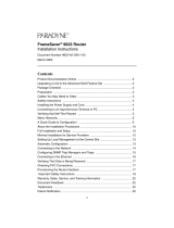
The CSU/DSU has an IDSL interface and is a manageable frame relay-aware endpoint.
The following diagram shows a typical use of the iMarc DSL CSU/DSU in a network.
The iMarc DSL CSU/DSU is available in two feature sets:
Diagnostic Feature Set provides basic frame relay and diagnostic capability.
Advanced SLM (Service Level Management) Feature Set provides basic features,
plus service level management and reporting capability.
Refer to System Overview in the iMarc SLV Technical Description for a list of iMarc DSL
CSU/DSU’s features, and the capabilities provided by each feature set.
Frame
Relay
CPE
Router/
FRAD
DSL ATM
Access
Network
iMarc
xDSL Unit
03-17390
Frame
Relay
DSL
A
L
A
R
M
S
Ma
j
o
r
Mi
nor
F
a
n
B
A
P
O
W
E
R
S
E
R
I
A
L
S
M
C
M
C
L
O
C
K
A
A
L
A
R
M
2
4
6
8
1
0
1
2
1
4
1
6
1
8
1
3
5
7
9
1
1
1
3
1
5
1
7
L
A
N
/
W
A
N
S
L
O
T
B
C
L
O
C
K
B
A
S
E
R
I
A
L
M
C
C
A
C
A
L
A
R
M
48V RTN
48V NEG
P
O
W
E
R
E
N
T
R
Y
M
O
D
U
L
E
L
E
F
T
U
N
I
T
:
L
I
N
E
A
R
I
G
H
T
U
N
I
T
:
L
I
N
E
B
W
A
R
N
I
N
G
!
P
O
W
E
R
M
U
S
T
B
E
D
I
S
C
O
N
N
E
C
T
E
D
A
T
T
H
E
S
O
U
R
C
E
B
E
F
O
R
E
R
EM
O
V
I
N
G
O
R
I
N
S
TA
L
L
IN
G
T
H
I
S
P
W
R
E
N
T
R
Y
M
O
D
U
L
E
48V RTN
48V NEG
P
O
W
E
R
E
N
T
R
Y
M
O
D
U
L
E
L
E
F
T
U
N
I
T
:
L
I
N
E
A
R
I
G
H
T
U
N
I
T
:
L
I
N
E
B
W
A
R
N
I
N
G
!
P
OW
E
R
M
U
S
T
B
E
D
I
S
C
O
N
N
E
C
T
E
D
A
T
T
H
E
S
O
U
R
C
E
B
E
F
O
R
E
R
E
M
O
V
I
N
G
O
R
I
N
S
T
A
L
L
IN
G
T
H
IS
P
W
R
E
N
T
RY
M
O
D
U
L
E
AT M
Switch
Copper
Loop
AT M
PVC
AT M
Switch
Customer Premises –
Remote Site
DSLAM
TDM
Access
Network
FR Network
FR/ATM
IWF
AT M
Switches
FR
Switches
Frame Relay NSP’s Network
DHCP
Server
Router
iMarc
Endpoint
Customer Premises –
HQ Site
LAN
Frame Relay
NSP's
Network
Operations
Center
OpenLane
NMS
DSL Provider's
Network
Operations
Center
OpenLane
NMS

3
Upgrading a Unit to Advanced SLM Feature Set
An iMarc DSL CSU/DSU with the Diagnostic Feature Set can be upgraded to the
Advanced SLM Feature Set at any time by ordering an iMarc Advanced SLM Activation
Certificate (Feature Number 9720-C1-220). A certificate can be ordered for a single
CSU/DSU, or for many CSU/DSUs. You must specify the model to be activated, your
OpenLane SLM system license key number, and the number of router activations to be
included on the certificate.
The OpenLane
®
SLM system, Release 5.3 or later, is required to schedule the activation
of Advanced SLM features and to manage the certificate activations included in the
certificate.
To learn more about activating Advanced SLM capability, refer to the iMarc SLV
Activation Instructions (Document No. 9000-A2-GK43), or contact your sales
representative.
Product Documentation Online
Complete documentation for this product is available at www.paradyne.com.
Select Library →Technical Manuals →iMarc IP/Frame Relay Devices.
Select the following documents:
iMarc SLV Technical Description (9000-A2-GB30)
iMarc SLV Configuration Reference (9000-A2-GB31)
iMarc SLV SNMP Reference (9000-A2-GB32)
iMarc SLV Operations Guide (9000-A2-GB33)
To order a paper copy of a Paradyne document:
Within the U.S.A., call 1-800-PARADYNE (1-800-727-2396)
Outside the U.S.A., call 1-727-530-8623
Package Checklist
In addition to these instructions, verify that your package contains the following:
❑ iMarc DSL CSU/DSU
❑ Power cord with power transformer
❑ Cable tie for power cord strain relief
❑ DSL network access cable (U.S. models only)
Be sure to register your warranty at www.paradyne.com/warranty.

4
Wiring and Cables You May Need
The following wiring and cables are used with this product, which uses standard
interface connectors:
❑ Standard connectors: An 8-position, RJ49C-type modular wall jack for the DSL
network connection. Pins 4 and 5 are used for Ring and Tip, respectively.
❑ DSL wiring: Unshielded twisted-pair wiring (CAT3, or better). The CAT3 wiring must
meet EIA/TIA-568 specifications with 24 AWG (.5 mm) or 26 AWG (.4 mm).
❑ Ethernet wiring: Twisted-pair wiring (CAT5, or better). The CAT5 wiring must meet
EIA/TIA-568 specifications with 24 AWG (.5 mm) or 26 AWG (.4 mm).
For standard cables, refer to Cables and Connectors on page 22 for standard pin
numbers. For Paradyne cables, contact your sales representative to order them.
Interface
Connection Cables
Feature or
Part Number
COM
Communication
port to a PC or
asynchronous
terminal
Shielded DB9-to-DB9, Standard EIA-232
straight-through cable —
ETHERNET
Ethernet port to a
NIC on a PC or an
Ethernet hub
For connection to a PC NIC:
Standard Ethernet crossover cable 9008-F1-550
For connection to an Ethernet Hub:
Standard Ethernet straight-through cable 035-0349-1431
PORT
User data port to a
DTE
Shielded standard straight-through
DB25-to-DB25 cable for EIA-530-A
For V.35, add DB25-to-MS34 cable, or
DB25-to-MS34 adapter
For X.21, add DB25-to-DB15 adapter
—
3100-F1-570
3100-F1-572
3100-F1-571
NET
Network port to the
DSL wall jack
Standard straight-through RJ49C-type DSL
network cable with 8-pin modular connectors.
Supplied with U.S. models.
3100-F1-500

5
Installing the CSU/DSU
Place the iMarc DSL CSU/DSU on a flat surface with clearance for the rear connectors.
Procedure
1. Use an 8-pin modular straight-through cable for the network connection. Insert one
end of the cable into the jack labeled NET. Insert the other end into the wall jack for
DSL data communications.
DSL
Network
02-17315
ETHERNET
P
O
R
T
COM
POW
ER
NET
NET

6
2. Use an 8-pin Ethernet cable for the Ethernet connection for local management.
Insert one end of the cable into the jack labeled ETHERNET.
— Use a straight-through cable to connect the other end of the cable to an
Ethernet hub. Do not connect to the hub’s optional Uplink connection with a
straight-through cable; the Uplink connection requires an Ethernet crossover
cable.
– or –
— Use an Ethernet crossover cable to connect to a PC with an Ethernet Network
Interface Card (NIC) installed, or to a hub’s Uplink connection.
02-17316
Hub
ETHERNET
P
O
R
T
COM
POW
ER
NET
Ethernet
Straight-Through
Cable
ETHERNET

7
3. Connect one end of the DTE’s cable to the user data port labeled PORT. Tighten
the screws on each side of the connector. Attach a cable adapter, if required. (See
Wiring and Cables You May Need on page 4.) Plug the other end of the cable or
adapter into the DTE (router or FRAD).
02-17317
ETHERNET
P
O
R
T
COM
POW
ER
NET
DTE
PORT

8
4. Use a VT100-compatible asynchronous terminal or a PC to set up management
access to the unit. Insert the DB9 plug end of an EIA-232 cable into the CSU/DSU’s
COM port. Tighten the screws on each side of the connector. Insert the other end of
the cable into the terminal or PC.
The terminal or PC’s configuration must be compatible with the CSU/DSU’s. Refer
to the procedure on page 13 under Configuration Setup. If connecting an external
modem to the COM port, refer to Connecting an External Modem on page 27.
COM
Port
02-17318
ETHERNET
P
O
R
T
COM
POW
ER
NET
VT100
Terminal

9
5. Insert the supplied power cord’s round end into the jack labeled POWER.
Depending on the model, your power supply plugs directly into a grounded outlet or
has a detachable cord that plugs into an outlet.
— If you have a wall-mount transformer, plug the transformer into a grounded AC
outlet.
— If you have a table-top transformer, verify that the cord is firmly attached to the
transformer, and plug the other end of the cord into a grounded AC outlet.
Install the supplied tie wrap for strain relief, as shown.
Installation of the hardware is now complete. When the power cord is installed, the
CSU/DSU goes through a power-on self-test.
02-17319
ETHERNET
P
O
R
T
COM
POW
ER
NET
Grounded
Power
Outlet
Tie
Wrap
Power
Jack

10
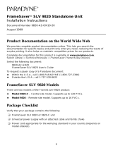
Power-On
When power is applied, the CSU/DSU performs self-diagnostics and the PWR LED is
on. The self-diagnostics include a power-on self-test where all of the LEDs are on.
Refer to Status LEDs on page 11 for information about the LEDs. Refer to
Troubleshooting on page 12 for LED indications requiring action.
iMarc DSL 9720 CSU/DSU
03 17411
OK
OK
ALM
TEST
FR
DSL
NetworkSystem
Por t
9720
DSL
IDSL
R

11
Status LEDs
After a successful self-test, the LEDs should appear as indicated in BOLD in the
Condition column below.
Label Indication Color Condition
System LEDs
OK Power and
Operational
Status
Green ON – The unit has power.
OFF – The unit is in a power-on self-test, or
there is a failure.
ALM Operational
Alarm (Fail)
Red ON – The unit has been reset, or an error has
been detected.
OFF – No failures have been detected.
TEST Test Mode Yellow ON – A loopback or test pattern is in progress,
initiated locally, remotely, or via the network.
OFF – No tests are active.
Network LEDs
FR LMI Status Green ON – The LMI is up.
OFF – The LMI is down.
DSL DSL Link
Status
Green ON – The DSL link is ready to transmit and
receive data.
OFF – The DSL link has not been established.
Port LED
OK Port Status Green ON – The user data port is up and ready for
operation.
OFF – No device is detected on the user data
port.

12
Troubleshooting
LED Symptom Action
All LEDs are on. If the LEDs remain on for more than ten minutes, the
CSU/DSU is not functional. Unplug the unit and reapply
power. If the ALM LED is still on, contact the service provider.
ALM LED only
remains on.
The power-on self-test may have failed. Unplug the unit and
reapply power. If the alarm LED is still on, contact the service
provider.
DSL LED is off. Verify that the DSL cable is securely installed on both ends.
Unplug the unit and reapply power. If the problem continues,
contact the service provider.
Port OK LED is off. Verify that the data port cable is securely installed at both
ends.
System OK LED is off. Check that the power cord is securely installed on both ends.
If no LEDs are on, the power supply may be defective. Test
the outlet to verify power. If the outlet has power and the
problem persists, contact your service representative.
If other LEDs are on, the OK LED may be burned out. Unplug
the unit and reapply power, and watch all LEDs as the unit
performs its power-on self-test. If the OK LED turns on then
turns off after the self-test, call your service representative.
TEST LED is on. A test initiated by the service provider may be active. Wait ten
minutes. If the LED does not go off, contact the service
provider.

13
Configuration Setup
Once the CSU/DSU is installed, it can be accessed locally through the menu-driven user
interface via an asynchronous terminal or PC connection, or remotely via a Telnet
session. The following provisioning can be set up:
Frame relay and physical layer provisioning – Typically set up by the LEC (Local
Exchange Carrier) or CLEC (Competitive LEC) using the menu-driven user
interface via an ASCII terminal or PC running a terminal emulation program, or a
Telnet session.
SLM provisioning – Typically set up by the frame relay service provider, LEC, or
CLEC.
As soon as the CSU/DSU’s COM port is connected to a terminal or PC, the menu-driven
user interface can be accessed. The terminal or PC’s configuration must be compatible
with the CSU/DSU’s COM port settings.
Procedure
To access the menu-driven user interface:
1. Verify the terminal or PC’s configuration:
— Data Rate is set to 19.2 kbps.
— Character Length is set to 8 data bits.
— Parity is set to None.
— Stop Bits is set to 1.
— Flow Control is set to None.
2. Press Enter to display the Main Menu.

14
If the Main Menu does not appear:
Press Enter again
Check the terminal or PC settings
Refer to Troubleshooting in the iMarc SLV Operations Guide
Verifying that Self-Test Passed
To verify that the unit passed its self-test, go to the System and Test Status screen.
Main Menu→Status→System and Test Status
The results of the self-test appear directly under the screen title.
If any failure messages appear, reset the unit by disconnecting, then reconnecting the
power cord. The unit will perform the self-test again. If the failure reappears, call your
service representative for assistance.
main 9720-SLV
Device Name: Node A 09/13/2002 09:02
MAIN MENU
Status
Test
Configuration
Auto-Configuration
Control
Easy Install
-----------------------------------------------------------------------------
Ctrl-a to access these functions E
xit

15
Menu Navigation
The CSU/DSU should operate using the default (factory-set) configuration options.
Refer to the following table for help in navigating the menus.
As an example, follow these steps to go to the Configuration Edit/Display menu so you
can start setting up the unit.
Procedure
To load a configuration for editing:
1. From the Main Menu, press the Tab key twice, or press the down (↓) arrow twice,
so the cursor is on Configuration.
2. Press Enter to select Configuration. The Load Configuration From menu appears.
3. Press Enter to select Current Configuration (the cursor is already on this selection).
The Configuration Edit/Display menu appears.
This sequence of steps would be shown as the menu selection sequence:
Main Menu → Configuration
Menu Hierarchy
The Menu Hierarchy on the following pages shows the organization of the iMarc DSL
CSU/DSU’s screens, which can help you navigate the menus and access information.
Press the . . . To . . .
Esc key Go back one screen or menu level. See Menu Hierarchy,
below.
Tab key, and
Up (↑), Down (↓ ),
Left (←), Right (→)
Arrow keys
Move the cursor from one menu item to the next.
Enter or Return key Complete the menu or option selection.
Spacebar Display the next available setting when changing a
configuration option. All the available settings for an option
appear at the bottom of the screen.

16
iMarc DSL 9720 Menu Structure
Status
System and Test Status Self-Test Results
Last System Reset
Health and Status
Tes t St atus
LMI Reported DLCIs DLCI
Status
CIR (bps)
IP Path Connection
Status
Device Name
IP Address
Status
Discovery Source
PVC Connection Status Source Link, DLCI, EDLCI
Primary Destination Link, DLCI,
EDLCI Status
IP Routing Table Destination
Mask
Gateway
Hop
Type
Interface
TTL
Performance Statistics Service Level Verification
DLCI
Frame Relay
Ethernet
Clear All Statistics
Trap Event Log Number of Trap Events
Time of Day
Event
Display LEDs and Control Leads
Identity System
NAM
Test
Network PVC Tests PVC Loopback
Send Pattern
Monitor Pattern
Data Port PVC Tests PVC Loopback
Send Pattern
Monitor Pattern
Connectivity
Data Port Physical Tests DTE Loopback
IP Ping
Lamp Test
Abort All Tests

17
Configuration
System Frame Relay and LMI
Class of Service Definitions
Service Level Verification
General
Network Physical
Frame Relay
DLCI Records
Data Ports Physical
Frame Relay
DLCI Records
PVC Connections Source Link, DLCI, EDLCI
Primary Destination Link, DLCI,
EDLCI
IP Path List Add and Display Static Paths
Management and
Communication Options
Node IP
Management PVCs
General SNMP Management
Telnet and FTP Session
SNMP NMS Security
SNMP Traps
Ethernet Management
Communication Port
External Modem (on Com Port)
Control
System Information Device Name
System Name, Location, Contact
Date
Time
Administer Logins Login ID
Password
Access Level
Change Operating Mode Back-to-Back Mode
Standard Mode
Select Software Release Current Release
Alternate Release
Switch & Reset
LMI Packet Capture
Utility
Capture Interface
Packet Capture Start/Stop
Status
Packets in Buffer
Display LMI Trace Log
Telnet (Release 2.1)
Reset Device

18
Using the Easy Install Screen
An Easy Install screen is provided for custom configurations, but is not required for
normal installation. You can configure the CSU/DSU by making selections from the
Configuration Edit/Display menu.
Procedure
1. Select the Easy Install feature.
Main Menu→Easy Install
Easy Install Screen Example
2. Enter the Node IP Address and Node Subnet Mask.
3. Specify TS Access if a Troubleshooting (TS) DLCI is being set up for remote access
by the service provider.
Easy Install
Node IP Address
Node Subnet Mask
TS Access
Create Dedicated Network
Management Link
Ethernet Port Options Screen
Network 1 Operating Rate
Network 1 Channel
main/easy_install 9720-SLV
Device Name: Node A 09/13/2002 08:05
EASY INSTALL
Node IP Address: 000.000.000.000 Clear
Node Subnet Mask: 000.000.000.000 Clear
TS Access: None
Create a Dedicated Network Management Link
Ethernet Management Options Screen
Network 1 Operating Rate (Kbps): AutoRate
-----------------------------------------------------------------------------
Ctrl-a to access these functions, ESC for previous menu MainMenu Exit
Save

19
4. Select Create a Dedicated Network Management Link to set up for permanent
remote access by the NOC. Enter a DLCI at the resulting prompts.
5. If Ethernet management will be used, select Ethernet Management Options Screen
to go directly to the Ethernet Management Options input screen.
— Enable the interface (Status).
— Respond Yes to the prompt Would you like to set the Node’s
Default IP Destination to Ethernet?
— Enter the IP Address and Subnet Mask for the Ethernet interface.
— Enter the Default Gateway Address (the IP Address that will be used for
packets without a specified route).
— Enable Proxy ARP, or leave it disabled.
— Press the Esc key to return to the Easy Install screen.
6. Change Network 1 Operating Rate (Kbps), if desired. The default is AutoRate.
7. S
ave the configuration.
Saving a Configuration
Procedure
To save configuration changes:
1. Press Ctrl-a to switch to the function keys area at the bottom of the screen.
2. Type s (S
ave) and press Enter. The Save Configuration To menu appears.
3. Press Enter again to save your changes to the Current Configuration (the cursor is
already on this selection).
To return to the Main Menu, press Ctrl-a, type m (M
ainMenu), and press Enter.

20
Completing Setup From the NOC
Procedure
1. Access the remote CSU/DSU on the TS Management Link that was set up at the
remote site in Step 4 on page 19 of Using the Easy Install Screen.
2. Ping the CSU/DSU five times within five seconds. The unit automatically accepts
the destination IP address of the ping as its temporary IP address.
3. If necessary, open a Telnet session and configure any specific configuration options
that require input or changes from default settings.
Configuring SNMP Trap Managers and Traps
Procedure
To enter SNMP managers and configure traps:
1. Select SNMP Traps.
Main Menu→Configuration→Management and Communication→
SNMP Traps
2. Configure the following:
— Enable SNMP Traps.
— Identify the total Number of Trap Managers.
— Specify the IP address for each NMS Trap Manager to which traps will be sent.
— Specify the Initial Route Destination for each Trap Manager. The default is
AutoRoute.
— Select or disable trap categories, as needed.
3. S
ave the configuration.
/