Page is loading ...

Instruction Manual
Albedometer
CMA series
Pyranometer
CMP series

Page 1
IMPORTANT USER INFORMATION
Reading this entire manual is recommended for full understanding of
the use of this product.
Should you have any comments on this manual we will be pleased to
receive them at:
Kipp & Zonen B.V.
Delftechpark 36, 2628 XH Delft, The Netherlands
or P.O. Box 507, 2600 AM Delft, The Netherlands
T : +31 (0)15 2755210
F : +31 (0)15 2620351
W : www.kippzonen.com
Kipp & Zonen reserves the right to make changes to the specifications
without prior notice.
WARRANTY AND LIABILITY
Kipp & Zonen guarantees that the product delivered has been
thoroughly tested to ensure that it meets its published specifications.
The warranty included in the conditions of delivery is valid only if the
product has been installed and used according to the instructions
supplied by Kipp & Zonen.
Kipp & Zonen shall in no event be liable for incidental or consequential
damages, including without limitation, lost profits, loss of income, loss of
business opportunities, loss of use and other related exposures,
however used, rising from the faulty and incorrect use of the product.
User made modifications can affect the validity of the CE declaration.
COPYRIGHT
©
2006 KIPP & ZONEN
All rights are reserved. No part of this publication may be reproduced,
stored in a retrieval system or transmitted in any form or by any means,
without permission in written form from the company.
Manual version: 0806

Page 2
Declaration of Conformity
According to EC guideline 89/336/EEC 73/23/EEC
We Kipp & Zonen B.V.
Delftechpark 36
2628 XH Delft
The Netherlands
Declare under our sole responsibility that the products
Type: CMP 3 / CMP 6 / CMP 11 / CMP 21 / CMP 22
Name: Pyranometer
and
Type: CMA 6 / CMA 11
Name: Albedometer
to which this declaration relates are in conformity with the following
standards
Imissions EN 50082-1 Group standard
Emissions EN 50081-1 Group standard
EN 55022
Safety standard IEC 1010-1
Following the provisions of the directive.
B.A.H. Dieterink
President
KIPP & ZONEN B.V.

CMP/CMA series manual
Page 3
Table of Contents
IMPORTANT USER INFORMATION.......................................................................................................1
Declaration of Conformity.........................................................................................................................2
Table of Contents .....................................................................................................................................3
1. Introduction....................................................................................................................................5
2. Installation and operation...............................................................................................................6
2.1. Delivery..........................................................................................................................................6
2.2. Mechanical installation...................................................................................................................6
2.2.1. Installation for measurement of global radiation........................................................................6
2.2.2. Installation for measurement of radiation on inclined surfaces..................................................8
2.2.3. Installation for measurement of reflected radiation....................................................................8
2.2.4. Installation for measurement of diffuse radiation.......................................................................9
2.2.5. Installation for measurement of albedo......................................................................................9
2.2.6. Underwater use..........................................................................................................................9
2.3. Electrical installation ....................................................................................................................10
2.4. Operation.....................................................................................................................................11
2.5. Measurement uncertainty............................................................................................................11
2.6. Maintenance ................................................................................................................................13
3. Principle components of pyranometers.......................................................................................14
3.1. Dome ...........................................................................................................................................14
3.2. Detector .......................................................................................................................................15
3.3. Housing........................................................................................................................................15
3.4. Drying cartridge............................................................................................................................15
3.5. Cable and connector....................................................................................................................15
4. Pyranometer physical properties.................................................................................................16
4.1. Spectral range..............................................................................................................................16
4.2. Sensitivity.....................................................................................................................................16
4.3. Impedance...................................................................................................................................16
4.4. Response time.............................................................................................................................16
4.5. Non-linearity.................................................................................................................................17
4.6. Temperature dependence ...........................................................................................................17
4.7. Tilt error........................................................................................................................................17
4.8. Zero offset A ................................................................................................................................17
4.9. Zero offset B ...............................................................................................................................18
4.10. Operating temperature.............................................................................................................18
4.11. Field of view .............................................................................................................................18
4.12. Directional response ................................................................................................................18
4.13. Maximum irradiance.................................................................................................................18
4.14. Non-stability..............................................................................................................................19
4.15. Spectral selectivity ...................................................................................................................19
4.16. Environmental..........................................................................................................................19
4.17. Uncertainty...............................................................................................................................19
5. Calibration....................................................................................................................................20
5.1. Calibration principle .....................................................................................................................20
5.2. Calibration procedure at Kipp & Zonen .......................................................................................20
5.2.1. The calibration facility...............................................................................................................20
5.2.2. Calibration procedure...............................................................................................................20
5.2.3. Calculation................................................................................................................................21
5.2.4. Zero offset................................................................................................................................21
5.3. Traceability to World Radiometric Reference..............................................................................21
5.4. Recalibration................................................................................................................................21
6. CMP/CMA models.......................................................................................................................23
6.1. CMP 6 / CMA 6............................................................................................................................23
6.2. CMP 11 / CMA 11........................................................................................................................23

CMP/CMA series manual
Page 4
6.3.
CMP 21........................................................................................................................................24
6.4. CMP 22........................................................................................................................................24
6.5. CMP / CMA series performance specifications...........................................................................25
6.6. CMP / CMA series general specifications ...................................................................................26
7. Frequently asked questions.........................................................................................................27
8. Trouble shooting..........................................................................................................................28
Appendix I Radiometric terminology.......................................................................................................29
Appendix II 10k thermistor specifications...............................................................................................30
Appendix III Pt-100 specifications ..........................................................................................................31
Appendix IV classification According to WMO Guide 1996....................................................................32
Appendix V List of World and Regional Radiation Centres....................................................................33
Appendix VI Recalibration service..........................................................................................................34

CMP/CMA series manual
Page 5
1. Introduction
Dear customer, thank you for purchasing a Kipp & Zonen instrument. Please read this manual and the
separate instruction sheet for a full understanding of the use of your pyranometer or albedometer.
A CMP series pyranometer or CMA series albedometer is a high quality radiometer designed for
measuring short-wave irradiance on a plane surface (radiant flux, W/m
2
) which results from the sum of
direct solar radiation and the diffuse radiation incident from the hemisphere above the instrument.
According to International Standard ISO 9060 and the World Meteorological Organisation (WMO) a
pyranometer is the designated type of instrument for the measurement of global or diffuse solar
radiation. All pyranometers and albedometers within the CMP/CMA series are compliant with one of
the classes specified by the international standards.
This manual, together with the instruction sheet, gives information related to installation, maintenance,
calibration, product specifications and applications of the CMP/CMA series. Note that the smaller CMP
3 pyranometer with a single glass dome is largely excluded from this manual due to the different
construction. However, the general definitions and principles also apply to this model.
If any questions should remain, please feel free to contact your Kipp & Zonen dealer or e-mail
For information about other Kipp & Zonen products or to check for any update of this manual, go to
www.kippzonen.com

CMP/CMA series manual
Page 6
2. Installation and operation
2.1. Delivery
Check the contents of the shipment for completeness (see below) and note whether any damage has
occurred during transport. If there is damage, a claim should be filed with the carrier immediately. In
this case, or if the contents are incomplete, your dealer should be notified in order to facilitate the
repair or replacement of the instrument.
Contents of delivery:
1. Radiometer
2. Sun shield
3. Cable with connector
4. Test reports
5. Instruction sheet
6. Radiometer fixing kit
7. 2 x desiccant bags
8. Product documentation CD
Although all CMP/CMA radiometers are weatherproof and suitable for harsh environmental conditions,
they have some delicate mechanical parts. Please keep the original packaging for safe transport of the
radiometer to the measurement site or for use when returning the radiometer for calibration.
The calibration certificate supplied with the instrument is valid for 1 year from the date of first use by
the customer, subject to the variations in performance due to specific operating conditions that are
given in the instrument specifications. The calibration certificate is dated relative to the time of
manufacture, or recalibration, but the instrument does not undergo any sensitivity changes when kept
in the original packing and not exposed to light. From the moment the instrument is taken from its
packaging and exposed to irradiance the sensitivity will deviate slightly with time. See the 'non-stability'
performance (maximum sensitivity change per year) given in the radiometer specification list.
2.2. Mechanical installation
The mechanical installation of the radiometer depends upon the measuring purpose. Different
measuring methods will be explained in the next paragraphs.
2.2.1. Installation for measurement of global radiation
The following steps must be carefully taken for optimal performance of the instrument.
1. Desiccant
Check the condition of the desiccant and replace if necessary, for example after a long storage period.
2. Location
Ideally the site for the radiometer should be free from any obstructions to the horizon above the plane
of the sensing element. If this is not possible, the site should be chosen in such a way that any
obstruction over the azimuth range between earliest sunrise and latest sunset should have an
elevation not exceeding 5
o
(the apparent sun diameter is 0.5
o
).

CMP/CMA series manual
Page 7
This is important for an accurate measurement of the direct solar radiation. The diffuse solar radiation
is less influenced by obstructions near the horizon. For instance, an obstruction with an elevation of 5
o
over the whole azimuth range of 360
o
decreases the downward diffuse solar radiation by only 0.8%.
The radiometer should be readily accessible for cleaning the outer dome and inspecting the desiccant
It is evident that the radiometer should be located in such a way that a shadow will not be cast upon it
at any time (for example by masts or ventilation ducts). Note that hot exhaust gas (> 100
o
C) will
produce some radiation in the spectral range of the radiometer and cause an offset in the
measurements. The radiometer should be distant from light-coloured walls or other objects likely to
reflect sunlight onto it, or emitting short-wave radiation.
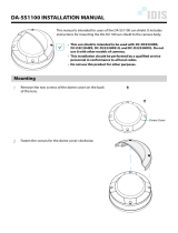
3. Mounting
The CMP pyranometer is provided with two holes for 5 mm bolts. Two each of stainless steel bolts,
washers, nuts and nylon insulation rings are provided in the fixing kit. The pyranometer should first be
secured lightly with the bolts to a solid and stable mounting stand or platform as shown in Figure 1.
After recalibration the nylon insulators must be replaced with new ones to prevent corrosion.
The mounting stand temperature can vary over a wider range than the air temperature. Temperature
fluctuations of the pyranometer body can produce offset signals, therefore it is recommended to isolate
the pyranometer thermally from the mounting stand by placing it on its levelling screws. Ensure that
there is a good electrical contact with earth to conduct away currents in the cable shield induced by
lightning.
Figure 1 Pyranometer installation
Note: After recalibration and/or reinstallation the nylon insulators must be replaced with new ones to
maintain durability.
4. Orientation
In principle no special orientation of the instrument is required, although the World Meteorological
Organisation (WMO) recommends that the signal lead is pointed towards the nearest pole, to minimise
heating of the electrical connections.

CMP/CMA series manual
Page 8
Figure 2 Mast construction
5. Level pyranometer
Accurate measurement of the global radiation requires proper levelling of the thermopile surface. Level
the instrument by turning the two levelling screws to bring the bubble of the spirit level centrally within
the marked ring. For easy levelling, first use the screw nearest to the spirit level. When the
pyranometer is placed horizontally using the bubble level, or when it is mounted with its base directly
on a horizontal plane, the thermopile is horizontal within 0.1
o
.
6. Secure pyranometer
Secure the pyranometer tightly with the two stainless steel bolts. Ensure that the pyranometer
maintains the correct levelled position!
7. Fit cable and sun shield
Locate the cable plug correctly in the radiometer socket (it only fits one way) and screw the plug
locking ring hand-tight. Finally, clip on the sun shield to prevent excessive heating of the radiometer
body. The bubble level is visible through the top of the sun shield for routine checks.
2.2.2. Installation for measurement of radiation on inclined surfaces
It is advised to pre-adjust the levelling screws on a horizontal surface for easy orientation of the
instrument parallel to the inclined surface. Because the temperature of the mounting stand is expected
to rise considerably (more than 10
o
C above air temperature), the body must be thermally isolated by
the levelling screws from the stand. This will promote a thermal equilibrium between domes and body
and decrease zero offset signals.
2.2.3. Installation for measurement of reflected radiation
In the inverted position the pyranometer measures reflected
global radiation. According to the WMO the height should be 1
m to 2 m above a uniform surface covered by short grass.
The mounting device should not interfere significantly with the
field of view of the instrument. The upper plate prevents
excessive heating of the pyranometer body by the solar
radiation and, if large enough, it keeps the lower screen free of
precipitation. The lower glare screen prevents direct
illumination of the domes by the sun at sunrise and sunset and
is available as an accessory kit for the CMP series.
Offset signals generated in the pyranometer by thermal effects
are a factor of 5 more significant in the measurement of
reflected radiation due to the lower irradiance level. The mast
shown in Figure 2 intercepts a fraction D/2πS. of the radiation
coming from the ground. In the most unfavourable situation
(sun at zenith) the pyranometer shadow decreases the signal
by a factor R
2
/H
2
.
A rule of thumb is:
A black shadow with radius = 0.1 H on the field below decreases the signal by1% and 99% of the
signal will originate from an area with radius 10 H.

CMP/CMA series manual
Page 9
2.2.4. Installation for measurement of diffuse radiation
For measuring sky radiation, the direct solar radiation is
intercepted by a small disk or sphere. The shadow of the disk
must cover the pyranometer domes completely. However, to
follow the sun's apparent motion, a power-driven tracking device
is necessary as shown in Figure 3.
This can be done using a Kipp & Zonen sun tracker, such as the
model 2 AP, designed to track the sun accurately under all
weather conditions. More information about the combination of
pyranometer and tracker is given in the sun tracker manual.
Alternatively, a static shadow ring can be used to intercept the
direct solar radiation; but it is less accurate and may require
periodic manual adjustment. At times the shadow ring also
intercepts a proportion of the diffuse sky radiation. Therefore,
corrections for this to the recorded data are necessary.
Kipp & Zonen produces a universal shadow ring, model CM 121, which is suitable for use at all
latitudes. In the CM 121 manual, installation instructions and correction factors are given.
2.2.5. Installation for measurement of albedo
An albedometer measures both the global solar radiation and the
reflected radiation form the surface below. It can be configured
from two CMP series pyranometers and a suitable mounting
plate, or by using a CMA series integrated albedometer.
The requirements for installation of the upper and lower
pyranometers are the same as in paragraphs 2.2.1 and 2.2.3 for
global and reflected radiation. A typical arrangement is shown in
Figure 4. According to the WMO the height should be 1 m to 2 m
above a uniform surface covered by short grass.
Installation of the CMA series differs slightly because there are
no levelling screws. The integrated mounting rod is fixed to the
mast. CMA has an integrated lower glare screen to prevent
direct illumination of the domes by the sun at sunrise and sunset.
The mast shown intercepts a fraction D/2πS of the radiation that Figure 4 Albedo configuration
is coming from the ground. In the most unfavourable situation
(sun at zenith) the pyranometer shadow decreases the signal by
a factor R
2
/H
2
.
2.2.6. Underwater use
The CMP/CMA radiometers are in principle watertight according to the IP 67 standard. However, the
hemispherical air cavity under the dome(s) acts as a negative lens. The parallel beam of direct solar
radiation becomes divergent after the passage of the outer dome. Consequently the intensity at the
sensor is lower than outside the dome(s). The calibrated sensitivity figure is not valid in this case and
must be derived empirically.
Figure 3 2AP Sun Tracker with
shaded pyranometer

CMP/CMA series manual
Page 10
2.3. Electrical installation
As standard the CMP/CMA is supplied with a waterproof connector pre-wired to 10 m cable with a
number of leads and a shield covered with a black sleeve. The number of connector pins and cable
leads depends upon the model of radiometer and whether a temperature sensor is fitted (and which
type). The colour code of the wires and the connector pin numbers are shown on the instruction sheet.
Longer cables are available as options.
Preferably, secure the radiometer with its levelling screws or mounting rod to a metal support with a
good connection to earth (e.g. by using a lightning conductor).
The shield of the cable is connected to the aluminium radiometer housing through the connector body.
The shield at the cable end may be connected to ground at the readout equipment. Lightning can
induce high voltages in the shield but these will be led off at the pyranometer and data logger.
Kipp & Zonen pyranometer cables are of low noise type, but bending the cable produces small voltage
spikes, a tribo-electric and capacitance effect. Therefore, the cable must be firmly secured to minimise
spurious responses during stormy weather.
The impedance of the readout equipment loads the temperature compensation circuit and the
thermopile. It can increase the temperature dependency of the pyranometer. The sensitivity is affected
more than 0.1% when the load resistance is less than 100 kΩ. For this reason we recommend the use
of readout equipment with an input impedance of 1 MΩ or more. The solar integrators, data loggers
and chart recorders from Kipp & Zonen meet these requirements.
Long cables may be used, but the cable resistance must be smaller than 0.1% of the impedance of the
readout equipment. It is evident that the use of attenuator circuits to modify the calibration factor is not
recommended because the temperature response will also be affected.
A high input bias current at the readout equipment can produce several micro-Volts across the
impedance of the pyranometer and cable. The zero offset can be verified by replacing the pyranometer
impedance at the readout equipment input terminals with a resistor.
The pyranometer can also be connected to a computer or data acquisition system. A low voltage
analogue input must be available. The resolution of the Analogue-to-Digital Converter (ADC) must
allow a system sensitivity of about 1 bit per W/m
2
. More resolution is not necessary during outdoor
solar radiation measurements, because pyranometers exhibit offsets up to ± 2 W/m
2
due to lack of
thermal equilibrium.
For amplification of the pyranometer signal Kipp & Zonen offers the AMPBOX signal amplifier. This
amplifier will convert the micro-Volt output from the pyranometer into a standard 4 – 20 mA signal. The
use of the AMPBOX amplifier is recommended for applications with long cables (> 100 m), electrically
noisy environments or data loggers with a current-loop input. The AMPBOX can be factory adjusted to
suit the sensitivity of an individual radiometer to produce a defined range, typically 4 – 20 mA
represents 0 – 1600 W/m
2
. The CMA series have two independent signal outputs, so two AMPBOX
amplifiers are required.

CMP/CMA series manual
Page 11
Figure 5 Non-linearity sensitivity variation of a CMP 22
2.4. Operation
After completing the installation the radiometer will be ready for operation.
The irradiance value (E
↓Solar
) can be simply calculated by dividing the output signal (U
emf
) of the
pyranometer by its sensitivity (S
ensitivity
) as shown in Formula 1.
For calculation of the solar irradiance (global or reflected) the following formula must be applied:
ensitivity
emf
Solar
S
U
E
=
↓
Formula 1
E
↓
Solar
= Solar radiation [W/m
2
]
U
emf
= Output of radiometer [µV]
S
ensitivity
= Sensitivity of radiometer [µV/W/m
2
]
To be certain that the quality of the data is of a high standard, care must be taken with daily maintenance
of the radiometer. Once a voltage measurement is taken, nothing can be done to retrospectively improve
the quality of that measurement.
2.5. Measurement uncertainty
When a pyranometer is in operation, the performance of it is correlated to a number of parameters,
such as temperature, level of irradiance, angle of incidence, etc. Normally, the supplied sensitivity
figure is used to calculate the irradiances. If the conditions differ significantly from calibration
conditions, uncertainty in the calculated irradiances must be expected.
For a secondary standard instrument (the highest quality) the WMO expects maximum errors in the
hourly radiation totals of 3%. In the daily total an error of 2% is expected, because some response
variations cancel each other out if the integration period is long. Kipp & Zonen expects maximum
uncertainty of 2% for hourly totals and 1% for daily totals for the CMP 22 pyranometer. Many years of
experience has shown that pyranometer performance can be improved concerning zero offset type A by
using a well designed ventilation system. The Kipp & Zonen CV 2 ventilation unit is recommended to
minimise this small remaining error.
For the CMP 22 the effect of each parameter on the sensitivity can be shown separately.
The non-linearity error, the sensitivity variation with irradiance, is the same for any CMP 22 and is
shown in Figure 5 for a range from 0 to 1000 W/m
2
referred to the calibration at 500 W/m
2
.

CMP/CMA series manual
Page 12
Figure 7 Relative directional error of a CMP 22
The temperature dependence of the sensitivity is a function of the individual CMP 22. For a given
CMP 22 the response lies in the region between the curved lines in Figure 6. The temperature
dependence of each CMP 21 and CMP 22 pyranometer is characterised and supplied with the
instrument. Each CMP 21 and CMP 22 has a built-in temperature sensor to allow corrections to be
applied if required.
The directional error is the summation of the azimuth and zenith error and is commonly given in %.
Figure 7 shows the maximum relative zenith error in any azimuth direction for the CMP 22. The
directional error of each CMP 21 and CMP 22 pyranometer is characterised and supplied with the
instrument.
Figure 6 Typical temperature dependency of a CMP 22

CMP/CMA series manual
Page 13
2.6. Maintenance
Once installed the radiometer needs little maintenance. The outer dome(s) must be cleaned and
inspected regularly, ideally every morning. On clear windless nights the outer dome temperature of
horizontally placed radiometers will decrease, even to the dew point temperature of the air, due to
infrared radiation exchange with the cold sky. (The effective sky temperature can be 30°C lower than
the ground temperature). In this case dew, glazed frost or hoar frost can be precipitated on the top of
the outer dome and can stay there for several hours in the morning. An ice cap on the dome is a strong
diffuser and increases the pyranometer signal drastically, up to 50% in the first hours after sunrise.
Hoar frost disappears due to solar radiation during the morning, but should be wiped of as soon as
possible manually.
The dome of the pyranometer can be ventilated continuously by a heated blower to keep the dome
above dew point temperature. The need for heating strongly depends upon local climatological
circumstances. Generally, heating is advised during cold seasons when frost and dew can be expected.
The Kipp & Zonen CV 2 ventilation unit is specially designed for unattended operation under most
weather conditions and has a choice of heating levels.
Note that the CMA albedometers and the CMP 3 pyranometer cannot be used with the CV 2 ventilation
unit.
A periodic check is to ensure that the radiometer is level and that the silica gel desiccant is still
coloured orange. When the orange silica gel in the drying cartridge is turned completely transparent
(normally after several months), it must be replaced by fresh silica gel as supplied in the small refill
packs. The content of one pack is sufficient for one complete refill. At the same time check that the
radiometer mounting is secure and that the cable is in good condition.
Some tips when changing the dessicant:
- Make sure the surfaces of the radiometer and the drying cartridge that touch the rubber o-ring are
clean (corrosion can do a lot of harm here and dirt, in combination with water, can cause this);
- The rubber o-ring is coated with a silicon grease to improve the seal. If the rubber o-ring looks dry
apply some grease to it (Vaseline will also do);
- Check that the drying cartridge is tightly threaded into the radiometer body.
It is very difficult to make the radiometers hermetically sealed; so, due to pressure differences between
the inside and the outside of the instrument, there will always be some exchange of (humid) air.
The radiometer sensitivity changes with time and with exposure to radiation. Calibration every two
years is advised. Further information about Kipp & Zonen recalibration services can be found in
Appendix VI.

CMP/CMA series manual
Page 14
3. Principle components of pyranometers
The detector of the Kipp & Zonen CMP/CMA series pyranometer is based on a passive thermal
sensing element called a thermopile. Although the detector construction differs from model to model,
the fundamental working principle is applicable to all CMP/CMA series radiometers.
The thermopile responds to the total power absorbed by the black surface coating, which is a non-
spectrally selective paint, and warm up. The heat generated flows through a thermal resistance to the
heat-sink (the pyranometer body). The temperature difference across the thermal resistance of the
detector is converted into a voltage as a linear function of the absorbed solar irradiance.
The rise of temperature is easily affected by wind, rain and thermal radiation losses to the environment
('cold' sky). Therefore the detector is shielded by two domes (the entry-level CMP 3 has only one dome
to reduce size and cost). These domes allow equal transmittance of the direct solar component for
every position of the sun on the celestial sphere. A drying cartridge (dessicator) in the radiometer
housing is filled with silica gel and prevents dew on the inner sides of the domes, which can cool down
considerably on clear windless nights.
Figure 8 Construction details of a pyranometer
3.1. Dome
The dome material of the radiometer defines the spectral measurement range of the instrument. In
general about 97 – 98% of the solar radiation spectrum will be transmitted through the domes and will
be absorbed by the detector. The solar irradiance can come from any direction within the hemisphere
above the radiometer and therefore the domes are designed to minimize errors in measurement at all
incident angles.
CMP/CMA series radiometers, except the CMP/CM 3, have two high optical grade hemispherical
domes, one inner dome and one outer dome. In the chapter ‘pyranometer physical properties’ the
physical relation between dome and pyranometer performance will be explained.
For each particular model the specific dome material and spectral range is shown in the chapter
containing the instrument specifications.

CMP/CMA series manual
Page 15
3.2. Detector
The thermopile sensing element is made up of a large number of thermocouple junction pairs
connected electrically in series. The absorption of thermal radiation by one of the thermocouple
junctions, called the active (or ‘hot’) junction, increases its temperature. The differential temperature
between the active junction and a reference (‘cold’) junction kept at a fixed temperature produces an
electromotive force directly proportional to the differential temperature created. This is a thermoelectric
effect. The sensitivity of a pyranometer depends on the individual physical properties of the thermopile
and construction. The sensitivity of each thermopile is unique and therefore each radiometer has
unique calibration factor, even with the same radiometer model.
On the top surface of the sensor a black paint is deposited which has a very rough structure containing
many micro-cavities that effectively ‘’trap’’ more than 97% of the incident radiation in a broad spectral
range. Furthermore, the spectral selectivity is less than 2%. This means that within the spectral range
of the pyranometer, the absorption for each wavelength is equal to within 2%. The black painted
sensing element forms the detector. Considering the long-term stability of the instrument, the black
paint is one of the most crucial and delicate parts of the pyranometer. Kipp & Zonen black paint gives
the best possible stability over a long period of time under all meteorological circumstances.
3.3. Housing
The radiometer housing accommodates all fundamental pyranometer parts. The anodized Aluminium
parts are light weight and give a high mechanical and thermal stability to the instrument. Due to its fine
mechanical construction all pyranometers are virtually sealed and comply to the international standard
IP 67. Each pyranometer model can be leveled by using the bubble level and two leveling feet. For
ease of maintenance the bubble level is situated next to the dome of the instrument and due to the
special shape of the sun shield it is visible from above. The sun shield acts to protects all the external
parts from radiation and to reduce solar heating of the housing.
3.4. Drying cartridge
In case moisture enters the radiometer body the silica-gel desiccant regulates the humidity level inside
the pyranometer. Initially the desiccant will have an orange color. After some time it becomes saturated
with moisture and the colour will change to become clear (transparent). At this time the contents of the
drying cartridge should be replaced with fresh, unsaturated orange colored desiccant as soon as
possible. Replacement desiccant is available through Kipp & Zonen distributors.
3.5. Cable and connector
For ease of installation and replacement during recalibration of the radiometer, the CMP/CMA series
are provided with a weather proof signal cable connector.
Kipp & Zonen radiometers use a custom-made cable that is selected as a low noise type particularly
suited to handle the low voltage output of the thermopile or of a temperature sensor.
The shield of the cable is connected to the metal body of the connector and preferably should be
connected to ground at the readout equipment. Cables come pre-wired to the connector plug in a
range of lengths.

CMP/CMA series manual
Page 16
4. Pyranometer physical properties
4.1. Spectral range
The spectrum of the solar radiation reaching the Earth’s surface is in the wavelength range between
280 nm and 4000 nm, extending from ultraviolet (UV) to the far infrared (FIR) as shown in Figure 9.
Due to the excellent physical properties of the glass dome and black absorber paint, Kipp & Zonen
CMP/CMA series radiometers are equally sensitive in a wide spectral range. 97-98% of the total
energy will be absorbed by the thermal detector. The CMP 22 pyranometer has a wider spectral range
due to the quartz domes used in its construction.
Figure 9 Solar irradiance spectrum at the Earth’s surface and pyranometer response
4.2. Sensitivity
The radiometer thermopile sensitivity is mainly determined by the physical properties of the detector
itself. The thermoelectric power, thermal conductivity of the junctions and the overall dimensions of the
sensing element are related to its sensitivity.
4.3. Impedance
The radiometer impedance is defined as the total electrical impedance at the radiometer output
connector fitted to the housing. It arises from the electrical resistance in the thermal junctions, wires
and passive electronics within the radiometer.
4.4. Response time
Any measuring device requires a certain time to react to a change in the parameter being measured.
The radiometer requires time to respond to change in the incident radiation. The response time is
normally quoted as the time for the output to reach 95% (sometimes 63%) of the final value following a
step-change in irradiance. It is determined by the physical properties of the thermopile and the
radiometer construction. CMP/CMA series radiometers have a fast response, which makes them
suitable for measuring solar radiation under variable weather conditions.

CMP/CMA series manual
Page 17
4.5. Non-linearity
The non-linearity of a radiometer is the percentage deviation in the sensitivity over an irradiance range
from 0 to 1000 W
.
m
-2
compared to the sensitivity calibration irradiance of 500 W
.
m
-2
. The non-linearity
effect is due to convective and radiative heat losses at the black absorber surface which make the
conditional thermal equilibrium of the radiometer non-linear.
4.6. Temperature dependence
The sensitivity change of the radiometer with ambient temperature change is related to the thermo-
dynamics of the radiometer construction. The temperature dependence is given as percent deviation
with respect to the calibrated sensitivity at +20°C. Some of the CMP/CMA series radiometer models
have passive electrical compensation circuits to minimise this effect. Each CMP 21 and CMP 22
pyranometer is supplied with an individual test certificate stating the temperature dependency in the
range from -20°C to +50°C, at 10°C intervals. The CMP 21 and CMP 22 are fitted as standard with an
internal temperature sensor to allow sensitivity corrections to be applied if desired.
4.7. Tilt error
This is the deviation from the sensitivity at 0° tilt (exactly horizontal) over the range from 0° to 90° tilt
under 1000 W
.
m
-2
normal incidence irradiance. The tilt response is proportional to the incident
radiation. The error could be corrected for, in applications where it is necessary to install the
pyranometer on an inclined surface, but is usually insignificant.
4.8. Zero offset A
By physical laws any object having a certain temperature will exchange radiation with its surroundings.
The domes of upward facing radiometers will exchange radiation primarily with the relatively cold
atmosphere. In general, the atmosphere will be cooler than the ambient temperature at the Earth’s
surface. For example, a clear sky can have an effective temperature up to 50°C cooler, whereas an
overcast sky will have roughly the same temperature as the Earth’s surface. Due to this the
pyranometer domes will ‘lose’ energy to the colder atmosphere by means of radiative transfer. This
causes the dome to become cooler than the rest of the instrument. This temperature difference
between the detector and the instrument housing will generate a small negative output signal which is
commonly called Zero Offset type A. This effect is minimized by using an inner dome. This inner dome
acts as a ‘radiation buffer’. The above is illustrated in Figure 10.
This effect can be minimized by applying appropriate
ventilation of the instrument. The CV 2 ventilation unit is
specially designed for the CMP series, except CMP 3.
Figure 10 Zero Offset type A

CMP/CMA series manual
Page 18
4.9. Zero offset B
Proportionally to the ambient temperature the instrument temperature varies and causes heat currents
inside the instrument. This will cause an offset commonly called Zero Offset type B. It is quantified as
the response in W/m
2
to a 5 K/hr change in ambient temperature.
4.10. Operating temperature
The operating temperature range of the radiometer is determined by the physical properties of the
individual parts. Within the specified temperature range Kipp & Zonen radiometers can be operated
safely. Outside this temperature range special precautions should be taken to prevent any physical
damage or performance loss of the radiometer. Please contact your distributor for further information
regarding operation in unusually harsh temperature conditions.
4.11. Field of view
The field of view is defined as the unobstructed open viewing angle of the radiometer. ISO and WMO
require that a pyranometer for the measurement of global solar radiation has a field of view of 180° in
all directions (i.e. a hemisphere). The inherent field of view of the instrument should not be confused
with the clear field of view of the installation location.
4.12. Directional response
Radiation incident on a flat horizontal surface originating
from a point source with a defined zenith position will have
an intensity value proportional to the cosine of the zenith
angle of incidence. This is sometimes called the ‘cosine-
law’ or ‘cosine-response’ and is illustrated in figure 11.
Ideally a pyranometer has a directional response which is
exactly the same as the cosine-law. However, in a
pyranometer the directional response is influenced by the
quality, dimensions and construction of the domes. The
maximum deviation from the ideal cosine-response of the
pyranometer is given up to 80° angle of incidence with
respect to 1000 W/m
2
irradiance at normal incidence (0°).
Figure 11 Solar zenith angle
4.13. Maximum irradiance
The maximum irradiance is defined as the total irradiance level beyond which physical damage may
occur to the instrument.

CMP/CMA series manual
Page 19
4.14. Non-stability
This is the percentage change in sensitivity over a period of one year. This effect is mostly due to
degradation by UV radiation of the black absorber paint on the sensing element surface. Kipp & Zonen
recommends recalibration every two years. However, for quality assurance purposes some institutes,
companies or networks may require more or less frequent recalibration. Please read the chapter on the
calibration procedure for pyranometers for more information.
4.15. Spectral selectivity
Spectral selectivity is the variation of the dome transmittance and absorption coefficient of the black
detector paint with wavelength and is commonly specified as % of the mean value.
4.16. Environmental
The CMP/CMA series are intended for outdoor use under all expected weather conditions. The
radiometers comply with IP 67 and their solid mechanical construction is suitable to be used under all
environmental conditions within the specified ranges.
4.17. Uncertainty
The measurement uncertainty can be described as the maximum expected hourly or daily uncertainty
with respect to the ‘absolute truth’. The confidence level is 95%, which means that 95% of the data-
points lie within the given uncertainty interval representing the absolute value. Kipp & Zonen
empirically determine uncertainty figures based on many years of field measurements.
/