KitchenAid 720-0732 - Old Owner's manual
- Category
- Small kitchen appliances
- Type
- Owner's manual
This manual is also suitable for

®itchen_kid ®
FREESTANDING OLUDOOR GRILL
For questions about features, operation/performance, parts, accessories or service, call: 1-877-373-2301
or visit our website at www.Ne×gril.net
p
ASADORE AUTONOMO PARA EXTERIORES
Para consultas respecto a caracteristicas, funcionamiento, rendimiento, piezas, accesorios o servicio t_cnico, lame al: 1-877-373-2301
o visite nuestro sitio de internet en www.Nexgrill.net
P
GRIL D'EXTERIEUR AUTOPORTANT
Pour des questions & propos des caract_ristiques, du fonctionnement/rendement, des pieces, des accessoires ou du service,
composer le : 1-877-373-2301
ou visitez notre site web www.Nexgrill.net
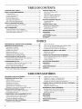
Table of Contents/[ndice/Table des matieres .................................................................. 2
720-0732 (LP) 730-0732 (NG)

TABLEOF CONTENTS
OUTDOOR GRILL SAFETY ............................................................ 3
INSTALLATION REQUIREMENTS ................................................ 5
Tools and Parts ............................................................................ 5
Location Requirements ................................................................ 5
Product Dimensions .................................................................... 6
Electrical Requirements ............................................................... 6
Gas Supply Requirements ........................................................... 7
Gas Connection Requirements .................................................... 7
INSTALLATION INSTRUCTIONS .................................................. 8
Freestanding Outdoor Grill Installation ........................................ 8
Make Gas Connection ............................................................... 11
GAS CONVERSIONS .................................................................... 14
Tools and Parts for Gas Conversion .......................................... 14
Conversion from LP Gas to Natural Gas ................................... 14
Check and Adjust the Burners ................................................... 18
OUTDOOR GRILL USE ................................................................ 19
Using Your Outdoor Grill ............................................................ 19
Hood Lights ................................................................................ 20
Using Your Searing Side Burner ................................................ 21
Using Your Rotisserie Burner ..................................................... 22
Rotisserie Cooking Tips ............................................................. 22
TIPS FOR OUTDOOR GRILLING ................................................ 23
Cooking Methods ....................................................................... 24
Grilling Chart ............................................................................... 24
OUTDOOR GRILL CARE .............................................................. 26
Replacing the Igniter Battery ...................................................... 26
Changing the Light Bulb ............................................................. 26
General Cleaning ........................................................................ 27
TROUBLESHOOTING .................................................................. 28
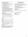
ASSISTANCE ................................................................................ 29
Accessories ................................................................................ 29
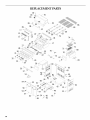
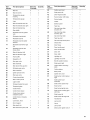
REPLACEMENT PARTS ............................................................... 30
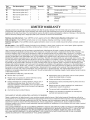
WAR RANTY .................................................................................. 32
INDICE
SEGURIDAD DEL ASADOR PARA EXTERIORES ..................... 34
REQUlSITOS DE INSTALACION ................................................. 36
Herramientas y piezas ................................................................ 36
Requisitos de ubicacion ............................................................. 36
Medidas del producto ................................................................ 37
Requisitos electricos .................................................................. 37
Requisitos del suministro de gas ............................................... 38
Requisitos para la conexion de gas ........................................... 39
INSTRUCCIONES DE INSTALACION ......................................... 40
Instalacion del asador autonomo para exteriores ..................... 40
Conexion del suministro de gas ................................................ 43
CONVERSIONES DE GAS ........................................................... 46
Herramientas y piezas para laconversion de gas ..................... 46
Conversion de gas LP a gas natural .......................................... 46
Revise y regule los quemadores ................................................ 50
USO DEL ASADOR PARA EXTERIORES ................................... 52
Como usar el asador para exteriores ........................................ 52
Luces de la capota ..................................................................... 54
Como usar el quemador lateral para dorado rapido ................. 54
Como usar el quemador del rostizador ..................................... 55
Consejos para la coccion con el rostizador ............................... 56
CONSEJOS PARA ASAR AL AIRE LIBRE .................................. 57
Metodos de coccion .................................................................. 57
Cuadro para asar........................................................................ 58
CUlDADO DEL ASADOR PARA EXTERIORES .......................... 61
Como reemplazar la bateria del encendedor ............................ 61
Como cambiar el foco ................................................................ 61
Limpieza general ........................................................................ 62
SOLUCION DE PROBLEMAS ...................................................... 64
ASISTENCIA .................................................................................. 64
Accesorios .................................................................................. 64
PIEZAS DE REPUESTO ............................................................... 65
GARANTiA ..................................................................................... 67
TABLEDES MATIERES
SECURITE DU GRIL D'EXTERIEUR ........................................... 69
EXIGENCES D'INSTALLATION ................................................... 71
Outils et pieces ........................................................................... 71
Exigences d'emplacement ......................................................... 71
Dimensions du produit ............................................................... 72
Specifications electriques .......................................................... 72
Specifications de I'alimentation en gaz ..................................... 73
Exigences concernant le raccordement au gaz ........................ 74
INSTRUCTIONS D'INSTALLATION ............................................ 75
Installation du gril d'exterieur autoportant ................................. 75
Raccordement au gaz ................................................................ 78
CONVERSIONS POUR CHANGEMENT DE GAZ ...................... 81
Outils et pieces pour conversion de gaz ................................... 81
Conversion de propane a gaz naturel ........................................ 81
Contr61e et reglage des brQleurs ............................................... 85
UTILISATION DU GRIL D'EXTI_RIEUR ....................................... 87
Utilisation du gril d'exterieur ...................................................... 87
Lampes sous le couvercle .......................................................... 89
Utilisation du brQleur &r6tissage lateral ..................................... 89
Utilisation du brQleur de tournebroche ...................................... 90
Conseils de cuisson & I'aide du tournebroche .......................... 91
CONSEILS POUR L'UTILISATION DU GRIL D'EXTERIEUR ....92
Methodes de cuisson ................................................................. 92
Tableau de cuisson au gril ......................................................... 93
ENTRETIEN DU GRIL D'EXTERIEUR ......................................... 96
Remplacement de la pile de I'allumeur...................................... 96
Changement de I'ampoule d'eclairage ...................................... 96
Nettoyage gen6ral ...................................................................... 97
DI_PAN NAGE................................................................................. 99
ASSISTANCE ................................................................................ 99
Accessoires ................................................................................ 99
PII_CES DE RECHANGE ............................................................ 100
GARANTIE ................................................................................... 102
2

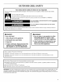
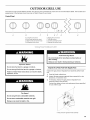
OUTDOOR GRILL SAFETY
Your safety and the safety of others are very important.
We have provided many important safety messages in this manual and on your appliance. Always read and obey all safety
messages.
This is the safety alert symbol.
This symbol alerts you to potential hazards that can kill or hurt you and others.
All safety messages will follow the safety alert symbol and either the word "DANGER" or "WARNING."
These words mean:
You can be killed or seriously injured if you don't immediately
follow instructions.
You can be killed or seriously injured if you don't follow
instructions.
All safety messages will tell you what the potential hazard is, tell you how to reduce the chance of injury, and tell you what can
happen if the instructions are not followed.
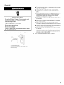
_, DANGER
If you smell gas:
1. Shut off gas to the appliance.
2. Extinguish any open flame.
3. Open lid.
4. If odor continues, keep away from the
appliance and immediately call your
gas supplier or your fire department.
_, WARNING
1. Do not store or use gasoline or other
flammable liquids or vapors in the
vicinity of this or any other appliance.
2. An LP cylinder not connected for use
shall not be stored in the vicinity of
this or any other appliance.
State of California Proposition 65 Warnings:
WARNING: This product contains one or more chemicals known to the State of California to cause cancer.
WARNING: This product contains one or more chemicals known to the State of California to cause birth defects or other
reproductive harm.
In the State of Massachusetts, the following installation instructions apply:
[] Installations and repairs must be performed by a qualified or licensed contractor, plumber, or gasfitter qualified or licensed by
the State of Massachusetts.
[] If using a ball valve, it shall be a T-handle type.
[] A flexible gas connector, when used, must not exceed 3 feet.
IMPORTANT: This grill is manufactured for outdoor use only. For grills that are to be used at elevations above 2000 ft (609.6 m) orifice
conversion is required. See "Gas Supply Requirements" section. It is the responsibility of the installer to comply with the minimum
installation clearances specified on the model/serial rating plate. The model/serial rating plate for freestanding models can be found on
the left-hand inside cabinet wall.

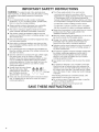
iMPORTANT SAFETY iNSTRUCTiONS
WARNING: To reduce the risk of fire, electrical shock,
injury to persons, or damage when using the outdoor cooking
gas appliance, follow basic precautions, including the
following:
[] Do not install portable or built-in outdoor cooking gas
appliances in or on a recreational vehicle, portable trailer,
boat or in any other moving installation.
[] Always maintain minimum clearances from combustible
construction, see "Location Requirements" section.
[] The outdoor cooking gas appliance shall not be located
under overhead unprotected combustible construction.
[] This outdoor cooking gas appliance shall be used only
outdoors and shall not be used in a building, garage, or any
other enclosed area.
[] Keep any electrical supply cord and fuel supply hose away
from any heated surfaces.
[] Keep outdoor cooking gas appliance area clear and free
from combustible materials, gasoline and other flammable
vapors and liquids.
[] Do not obstruct the flow of combustion and ventilation air.
Keep the ventilation openings of the cylinder enclosure free
and clear from debris.
[] Open the cabinet door and inspect the gas cylinder supply
hose before each use of the outdoor cooking gas
appliance. If the hose shows excessive abrasion or wear,
or is cut, it MUST be replaced before using the outdoor
cooking gas appliance. Contact your dealer and use only
replacement hoses specified for use with the outdoor
cooking gas appliance.
[] Visually check the burner flames.
They should be blue. Slight
yellow tipping is normal for LP
gas. The flames should be
approximately 1" (2.5 cm) high.
[] Check and clean burner/venturi tube for insects and insect
nest. A clogged tube can lead to fire under the outdoor
cooking gas appliance.
SAVE THESE
[] The LP gas supply cylinder to be used must be:
- constructed and marked in accordance with the
Specification for LP Gas Cylinders of the U.S. Department
of Transportation (DOT) or the National Standard of
Canada, CAN/CSA-B339, Cylinders, Spheres, and Tubes
for Transportation of Dangerous Goods; and Commission.
- provided with a listed overfilling prevention device.
- provided with a cylinder connection device compatible
with the connection for outdoor cooking gas appliances.
[] Always check connections for leaks each time you connect
and disconnect the LP gas supply cylinder. See
"Installation Instructions" section.
[] When the outdoor cooking gas appliance is not in use, the
gas must be turned off at the supply cylinder.
[] Storage of an outdoor cooking gas appliance indoors is
permissible only if the cylinder is disconnected and
removed from the outdoor cooking gas appliance.
[] Cylinders must be stored outdoors and out of the reach of
children and must not be stored in a building, garage, or
any other enclosed area.
[] The pressure regulator and hose assembly supplied with
the outdoor cooking gas appliance must be used. A
replacement pressure regulator and hose assembly
specific to your model is available from your outdoor
cooking gas appliance dealer.
[] Gas cylinder must include a collar to protect the cylinder
valve.
[] For appliances designed to use a CGA791 Connection:
Place a dust cap on cylinder valve outlet whenever the
cylinder is not in use. Only install the type of dust cap on
the cylinder valve outlet that is provided with the cylinder
valve. Other types of caps or plugs may result in leakage
of propane.
If the following information is not followed exactly, a fire
causing death or serious injury may occur.
[] Do not store a spare LP gas cylinder under or near this
outdoor cooking gas appliance.
[] Never fill the cylinder beyond 80 percent full.
INSTRUCTIONS

INSTALLATION REQUIREMENTS
Gather the required tools and parts before starting installation.
Read and follow the instructions provided with any tools listed
here.
Tools Needed
• Phillips screwdriver
• Wrench or pliers
• Pipe wrench
• Scissors or cutting pliers
(to remove tiedowns)
• Noncorrosive leak-
detection solution
Parts Supplied
• Gas pressure regulator/hose assembly set for 11" WCP LP
gas
• Right side shelf with sear burner
• Left side shelf
• Searing side burner control knob
• "AA" Batteries (1)
• Warming rack
• Cooking grid
• Side burner cooking grid
• Natural gas orifice for rotisserie/infrared burner
Parts Needed
• 20 Ib LP gas fuel tank - approximately 18" (45.7 cm) height
Parts Needed for Conversion to Natural Gas
• Natural gas conversion kit Part Number 710-0003. See
"Assistance" section to order. The conversion kit includes:
• Natural gas regulator 4" W.C. (marked "Natural Gas
Regulator")
• 10 ft (3.0 m) Natural gas hose with quick connector
• 5.9" (150 mm) Natural gas regulator hose
• 6 mm nut driver
• 6 mm wrench
• Hex key
• Gas line shutoff valve
• 1/2"male pipe thread nipple for connection to pressure
regulator.
• LP gas-resistant pipe-joint compound
• CSA design-certified outdoor flexible stainless steel
appliance connector (4-5 ft [1.2-1.5 m]) or rigid gas supply
line as needed.
Explosion Hazard
Do not store fuel tank in a garage or indoors.
Do not store grill with fuel tank in a garage or indoors.
Failure to follow these instructions can result in death,
explosion, or fire.
Fire Hazard
Do not use grill near combustible materials.
Do not store combustible materials near grill.
Doing so can result in death or fire.
Select a location that provides minimum exposure to wind and
traffic paths. The location should be away from strong draft
areas.
Do not obstruct flow of combustion and ventilation air.
Clearance to combustible construction for freestanding outdoor
grills:
• A minimum of 24" (61 cm) must be maintained between the
front of the grill hood, sides and back of the grill and any
combustible construction.
• A 24" (61 cm) minimum clearance must also be maintained
below the cooking surface, and the grill shall not be used
under overhead combustible construction.
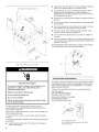
Rotisserie (accessory)*
If you equip your grill with a rotisserie, a 6" (15.2 cm) minimum
clearance is needed for the rotisserie motor.
A grounded, 3-prong outlet located to the left of the grill is
required.
*See "Assistance" section to order.

• Unplugfromtheoutletwhennotinuseandbeforecleaning.
Allowtocoolbeforeputtingonortakingoffparts.
• Donotoperateanyoutdoorcookinggasappliancewitha
damagedcord,damagedplug,oraftertheappliance
malfunctionsorhasbeendamagedinanymanner.Contact
themanufacturerforrepair.
• Donotletthecordhangovertheedgeofatableortouchhot
surfaces.
• Donotuseanoutdoorcookingapplianceforpurposesother
thanintended.
• Whenconnecting,firstconnectplugtotheoutdoorcooking
gasappliancethenplugapplianceintotheoutlet.
• UseonlyaGroundFaultInterrupter(GFI)protectedcircuit
withthisoutdoorcookinggasappliance.
• Donotremovethegroundprongorusewithanadapterof
2prongs.
• Useonlyextensioncordswitha3pronggroundingplugrated
forthepoweroftheequipmentandapprovedforoutdooruse
withaW-Amarking.
Themodel/serialnumberratingplateislocatedontheinsideof
theleftcabinetdoor.Seethefollowingillustration.
ElectricalShockHazard
Useonly a UL listed, 14 gauge, 3 wire extension cord
approved for outdoor use, marked W-A, with a
maximum length of 50 ft.
Plug into a grounded 3 prong outlet.
Do not remove ground prong.
Do not use an adapter.
Failure to follow these instructions can result in death,
fire, or electrical shock.
If codes permit and a separate ground wire is used, it is
recommended that a qualified electrician determine that the
ground path is adequate.
Check with a qualified electrician if you are not sure whether the
grill is properly grounded.
A 120-volt, 60-Hz, AC-only, 15-amp, fused electrical supply is
required.
It is recommended that a separate circuit servicing only this grill
be provided.
• To avoid electrical shock, do not immerse cord or plugs in
water or other liquid.
A.Model/serial number plate
Recommended Ground Method
The outdoor grill, when installed, must be electrically grounded in
accordance with local codes or, in the absence of local codes,
with the National Electrical Code ANSl/NFPA 70, or Canadian
Electrical Code, CSA C22.1.
Copies of the standards listed above may be obtained from:
CSA International
8501 East Pleasant Valley Rd.
Cleveland, Ohio 44131-5575
National Fire Protection Association
One Batterymarch Park
Quincy, Massachusetts 02269
g .........
A,, •...................."
A. 3-prong ground plug
B. 3-prong polarized type outdoor GFI outlet
C. Ground prong
6

Explosion Hazard
Use a new CSA International approved "outdoor"
gas supply line.
Securely tighten all gas connections.
if connected to LP, have a qualified person make sure
gas pressure does not exceed 11" (28 cm) water
column.
Examples of a qualified person include:
licensed heating personnel,
authorized gas company personnel, and
authorized service personnel.
Failure to do so can result in death, explosion, or fire.
Observe all governing codes and ordinances.
IMPORTANT: This installation must conform with all local codes
and ordinances. In the absence of local codes, installation must
conform with either the National Fuel Gas Code, ASNI Z223.1/
NFPA 54, Natural Gas and Propane Installation Code, CSA
B149.1, Propane Storage and Handling Code, B149.2, or the
Standard for Recreational Vehicles, ASNI A119.2/NFPA 1192 and
CSA Z240 RV Series Recreational Vehicle Code as applicable.
IMPORTANT: Grill must be connected to a regulated gas supply.
Refer to the model/serial rating plate for information on the type
of gas that can be used. If this information does not agree with
the type of gas available, check with your local gas supplier.
Gas Conversion:
No attempt shall be made to convert the grill from the gas
specified on the model/serial rating plate for use with a different
gas type without consulting the serving gas supplier. The
conversion kit supplied with grill must be used. See "Gas
Conversions" section for instructions.
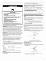
Gas Pressure Regulator
The gas pressure regulator supplied with this grill must be used.
The inlet (supply) pressure to the regulator should be as follows
for proper operation:
LP Gas:
Operating pressure: 11" (27.9 cm) WCP
Inlet (supply) pressure: 11" to 14" (27.9 cm to 35.5 cm) WCP
Natural Gas:
Operating pressure: 4" (10.2 cm) WCP
Inlet (supply) pressure: 7" to 14" (17.8 cm to 35.5 cm) WCP
maximum.
Contact local gas supplier if you are not sure about the inlet
(supply) pressure.
Burner Requirements for High Altitude
Input ratings shown on the model/serial rating plate are for
elevations up to 2,000 ft (609.6 m).
For elevations above 2,000 ft (609.6 m), ratings are reduced at a
rate of 4% for each 1,000 ft (304.8 m) above sea level. Orifice
conversion is required. See "Assistance" section to order.
Gas Supply Line Pressure Testing
Testing above 1/2psi (3.5 kPa) or 14" (35.5 cm) WCP (gauge):
The grill and its individual shutoff valve must be disconnected
from the gas supply piping system during any pressure testing of
that system at test pressures greater than 1/2psi (3.5 kPa).
Testing below 1/2psi (3.5 kPa) or 14" (35.5 cm) WOP (gauge) or
lower:
The grill must be isolated from the gas supply piping system by
closing its individual manual shutoff valve during any pressure
testing of the gas supply piping system at test pressures equal to
or less than 1/2psi (3.5 kPa).
20 Ib LP Gas Fuel Tank
This grill is equipped for use with a20 Ib LP gas fuel tank (fuel
tank not supplied). A gas pressure regulator/hose assembly is
supplied.
Any brand of 20 Ib LP gas fuel tank is acceptable for use with the
grill, provided that it is compatible with the grill's retention means
(tank tray included).
It is also design-certified by CSA International for local LP gas
supply or for Natural gas with appropriate conversion.
@
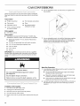
A. Gas pressure regulator/hose assembly
The 20 Ib LP gas fuel tank must be mounted and secured.
Door Style Tank Tray
1. Open cabinet doors.
2. Slide the tank tray locking bracket counterclockwise 90 ° and
pull out the tray.
A ......................................................<
A. Tanktray locking bracket
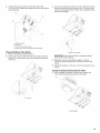
3.
Place the 20 Ib LP gas fuel tank bottom collar into the
mounting hole in the tank tray.

4.
5.
Tighten the locking screw against the bottom collar of the
20 Ib LP gas fuel tank to secure.
A _C
A. Locking screw
B. Bottom collar
C. Mounting hole
Slide the drawer with the 20 Ib LP gas fuel tank back into the
cabinet. Turn the tank tray locking bracket clockwise 90 ° to
tighten.
A. Tank tray locking bracket
Natural Gas Conversion
Conversion must be made by a qualified gas technician. The
qualified Natural gas technician shall provide the Natural gas
supply to the selected grill location in accordance with the
National Fuel Gas Code ANSI Z223.1/NFPA 54 - latest edition,
and local codes. For conversion to Natural gas, the Natural Gas
Conversion Kit supplied with the grill (on some models) or the
Natural Gas Conversion Kit Part Number 710-0003 must be
used. See "Assistance" section for information on ordering.
IMPORTANT: The gas installation must conform with local
codes, or in the absence of local codes, with the National Fuel
Gas Code, ANSI Z223.1/NFPA 54 - latest edition.
Follow instructions for converting to Natural gas in the "Gas
Conversions" section of this manual or the instructions supplied
with Natural Gas Conversion Kit Part Number 710-0003.
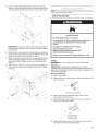
The gas supply line shall be equipped with an approved shutoff
valve. This valve should be located in the same area as the grill
and should be in a location that allows ease of opening and
closing. Do not block access to the shutoff valve. The valve is for
turning on or shutting off gas to the grill.
A
B
/
A. Gas supply line
B. Shutoff valve "open" position
C. To grill
INSTALLATION
INSTRUCTIONS
() / (X}_
Excessive Weight Hazard
Use two or more people to move and install grill.
Failure to do so can result in back or other injury.
Unpack Grill
1. Remove all packaging materials and remove grill from the
shipping base.
2. Move grill close to desired outdoor location.
3. Open the grill hood.
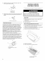
Remove Packaging Material Inside the Grill
1. Use a utility knife to cut yellow straps and packing tape to
open box from top and remove the boxes.
2. Remove the warming shelf and grill grates from inside the grill
and remove the package inside the firebox.
3. Remove foam block and wrap from inside the grill.
4. Replace the grill grates.
5. Place warming shelf on brackets as shown.
B
A. Warming shelf brackets
B. Warming shelf
8

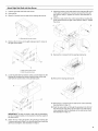
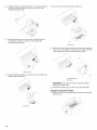
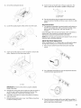
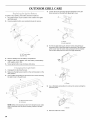
Attach Right Side Shelf with Sear Burner
1. Unpack right side shelf with sear burner. 7. Attach the bottom of the side shelf to the side panel (B and C)
2. Open grill lid. of the grill by inserting the 3 screws removed from the grill
side panel in Step 4. Tighten the screws. See illustration in
3. Remove 3 screws from the side of the searing side burner. Step 8.
8. Attach the side shelf to the control panel (D) by inserting the
screw removed from the grill control panel in Step 4. Tighten
the screw.
A
B
A.Searing sideburner screws
4. Remove the 3 screws on the grill side panel and 1 screw on
the grill control panel.
D
9. Remove the 3 screws from the searing side burner.
C
5.
A. Grill control panel screw
B. Grill side panel screws
Lower the side shelf so that the center post (A) slides into the
bracket (B) and align the bottom keyhole slots on the side
shelf with the screw holes on the grill side panel.
10. Remove the searing side burner.
6.
A
IMPORTANT: This step is meant to help with the installation,
but do not depend solely on the bracket to hold the weight of
the sear burner.
Attach the top of the side shelf to the grill (A) by inserting the
3 screws removed in Step 3 into the side shelf from inside the
grill hood and tighten. See illustration in Step 8.
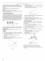
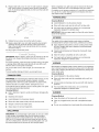
11. Remove the 2 screws from the side burner valve assembly.
See illustration in Step 13.
12. Push the valve stem out through the opening in the front of
the side burner shelf, lining up the holes in the side burner
valve assembly with the openings on the side burner shelf.
See illustration in Step 13.

13.Slidethebezelopeningoverthevalvestemandattachthe
sideburnervalveassemblyandbezeltothesideburnershelf
withthescrewsremovedinStep9.
A
16. Insert the valve stem into the knob and push knob into place.
III
iI
A. Bezel
B. Valve stem
14. Replace the searing side burner, angling it so that the valve
orifice goes into the side burner tube.
15. Connect electrical plugs on underside of sear burner.
17. The igniter battery is not factory installed. A "AA" size alkaline
battery is located in the accessory box on the grill grate.
Install battery at this time following the instructions in
"Replacing the Igniter Battery" section.
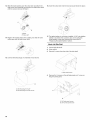
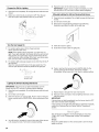
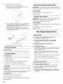
Attach Left Side Shelf
1. Unpack left side shelf.
2. Open grill lid.
3. Remove 3 screws from the side of the side shelf.
4=
A. Side shelf screws
Remove the 3 screws on the grill side panel and 1 screw on
the grill control panel.
...... J
A.Electrical plug from grill
B.Electrical plug from sear burner A
A. Grill side panel screws
B. Grill control panel screw
10

5.
Lower the side shelf so that the side shelf center post (A)
slides into the bracket (B) and align the bottom keyhole slots
on the side shelf with the screw holes on the grill side panel.
\
IMPORTANT: This step is meant to help with the installation,
but do not depend solely on the bracket to hold the weight of
the side shelf.
6. Attach the top of the side shelf to the grill (B) by inserting the
3 screws removed in Step 3 into the side shelf from inside the
grill hood and tighten. See illustration in Step 8.
7. Attach the bottom of the side shelf to the side panel (A and D)
of the grill by inserting the 3 screws removed from the grill
side panel in Step 4. Tighten the screws. See illustration in
Step 8.
8. Attach the side shelf to the control panel (C) by inserting the
screw removed from the grill control panel in Step 4. Tighten
the screw.
D
C
NOTE: If grill is to be converted to Natural gas, follow instructions
in the "Gas Conversions" section.
20 Ib LP Gas FuelTank
Explosion Hazard
Securely tighten all gas connections.
if connected to LP, have a qualified person make sure
gas pressure does not exceed 11" (28 cm) water
column.
Examples of a qualified person include:
licensed heating personnel,
authorized gas company personnel, and
authorized service personnel.
Failure to do so can result in death, explosion, or fire.
LP Gas:
IMPORTANT: A 20 Ib LP gas fuel tank must be purchased
separately.
IMPORTANT: The gas pressure regulator/hose assembly
supplied with the grill must be used. Replacement gas pressure
regulator/hose assembly specific to your model, is available from
your outdoor grill dealer.
Door Style Tank Tray
1. Open cabinet doors.
2. Slide the tank tray locking bracket counterclockwise 90 ° and
pull out the tray.
A ......................................................<_
A. Tanktray locking bracket
3.
4.
Place the 20 Ib LP gas fuel tank bottom collar into the
mounting hole in the tank tray.
Tighten the locking screw against the bottom collar of the
20 Ib LP gas fuel tank to secure.
A 0
2
A. Locking screw
B.Bottom collar
C. Mounting hole
5. Slide the tank tray with the 20 Ib LP gas fuel tank back into
the cabinet and lock the locking bracket.
11

To Connect the 20 Ib LP Gas Fuel Tank:
1. Check that the 20 Ib LP gas fuel tank is inthe "Off" position. If
not, turn the valve clockwise until it stops.
2. Check that the 20 Ib LP gas fuel tank valve has the proper
type-1 external male thread connections per ANSI Z21.81.
3. Check that the burner control knobs are in the "Off" position.
4. Remove any debris and inspect the valve connections, port,
and gas pressure regulator/hose assembly for damage.
NOTE: Always keep the LP cylinder at 90 ° (upright)
orientation to provide vapor withdrawal.
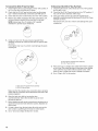
To Disconnect the 20 Ib LP Gas Fuel Tank:
1. Check that the burner control knobs are in the "Off" position
and the grill is cool.
2. Check that the 20 Ib LP gas fuel tank is in the "Off" position. If
not, turn the valve clockwise until it stops.
3. Using your hand, turn the gas pressure regulator/hose
assembly counterclockwise to disconnect to the 20 Ib LP gas
fuel tank as shown.
Hand loosen only. Use of a wrench could damage the quick
coupling nut.
5.
Using your hand, turn the gas pressure regulator/hose
assembly clockwise to connect to the 20 Ib LP gas fuel tank
as shown.
Hand tighten only. Use of a wrench could damage the quick
coupling nut.
A
A. Gas pressure regulator/hose assembly
B.20 Ib LP gas fuel tank
4. Place dust cap on cylinder valve outlet whenever the cylinder
is not in use. Only install the type of dust cap on the cylinder
valve outlet that is provided with the cylinder valve. Other
types of caps or plugs may result in leakage of propane.
5. Go to "Plug in Grill" in this section.
A. Gas pressure regulator/hose assembly
B. 20 Ib LP gas fuel tank
Make sure that the cylinder valve connection device properly
mates with the connection device attached to the inlet of the
pressure regulator.
6. Open the tank valve fully by turning the valve
counterclockwise. Wait a few minutes for gas to move
through the gas line.
7. Before lighting the grill, test all connections by brushing on an
approved noncorrosive leak-detection solution. Bubbles will
show a leak.
8. If a leak is found, turn the tank valve off and do not use the
grill. Contact a qualified gas technician to make repairs.
9. Go to "Check and Adjust the Burners" section.
12

PluginGrill
Electrical Shock Hazard
Use only a UL listed, 14 gauge, 3 wire extension cord
approved for outdoor use, marked W=A, with a
maximum length of 50 ft.
Plug into a grounded 3 prong outlet.
Do not remove ground prong.
Do not use an adapter.
Failure to follow these instructions can result in death,
fire, or electrical shock.
1. Plug extension cord into grounded 3-prong GFI outlet.
To avoid electrical shock, do not immerse cord or plugs in
water or other liquid.
Unplug from the outlet when not in use and before
cleaning. Allow to cool before putting on or taking off
parts.
Do not operate any outdoor cooking gas appliance with a
damaged cord, damaged plug, or after the appliance
malfunctions or has been damaged in any manner.
Contact the manufacturer for repair.
Do not let the cord hang over the edge of a table or touch
hot surfaces.
Do not use an outdoor cooking appliance for purposes
other than intended.
When connecting, first connect plug to the outdoor
cooking gas appliance then plug appliance into the outlet.
Use only a Ground Fault Interrupter (GFI) protected circuit
with this outdoor cooking gas appliance.
Do not remove the ground prong or use with an adapter
of 2 prongs.
Use only extension cords with a 3 prong grounding plug
rated for the power of the equipment and approved for
outdoor use with a W-A marking.
2. Go to "Check and Adjust the Burners" section.
A. 3-prong ground plug
B. 3-prong polarized type outdoor GFI outlet
C. Ground prong
13

GAS CONVERSIONS
Gather the required tools and parts before starting installation.
Read and follow the instructions provided with any tools listed
here.
6.
Use an adjustable wrench to remove the LP regulator from
the manifold.
Tools needed
• Phillips screwdriver
• Pipe wrench
• Adjustable wrench
• 6 mm socket and wrench
or 6 mm nut driver
• Thin flat-blade screwdriver
• Pliers
• Pipe thread sealant
certified for LP gas
Parts supplied
• Natural gas orifices
Parts needed
• Natural gas conversion kit Part Number 710-0003. See
"Assistance" section to order. The conversion kit includes:
• Natural gas regulator 4" W.C. (marked "Natural Gas
Regulator")
• 10 ft (3.0 m) Natural gas hose with quick connector
• 5.9" (150 mm) Natural gas regulator hose
• 6 mm nut driver
• 6 mm wrench
• Hex key
IMPORTANT: Gas conversions must be done by a qualified
installer. Before proceeding with conversion, shut off the gas
supply to the appliance prior to disconnecting the electrical
power.
Explosion Hazard
Use a new CSA International approved "outdoor"
gas supply line.
Securely tighten all gas connections.
Failure to do so can result in death, explosion, or fire.
Installation of the regulator
1. Turn off the main gas supply valve.
2. Unplug grill or disconnect power.
3. Disconnect 20 Ib LP gas fuel tank (if present).
4. Turn off all burner control valves.
5. Remove the 20 Ib LP gas fuel tank (if present) from the grill
cart.
7.
Use an adjustable wrench to install the Natural gas regulator
hose to the manifold and secure. Attach the Natural gas
regulator to the side panel inside the grill cart with the two
screws that are preassembled on the regulator.
............... p..
Make Gas Connection
1. A combination of pipe fittings must be used to connect the
grill to the existing gas line.
• The 10 ft (3.0 m) PVC flexible gas supply hose design-
certified by CSA must be used.
• Pipe-joint compounds suitable for use with Natural gas
must be used. Do not use Teflon ®ttape.
• There must be a certified manual shutoff valve in the gas
supply line near the grill for easy access.
2. Connect the brass connector on one end of the 10 ft (3.0 m)
PVC flexible gas supply hose to the Natural gas pressure
regulator.
1-®TEFLON is a registered trademark of E.I. Du Pont De Nemours and Company.
14

3.
Connect the quick connector on the other end of the
10 ft (3.0 m) PVC flexible gas supply hose to the rigid Natural
gas supply pipe.
3. Use a 6 mm socket and wrench or 6 mm nut driver to remove
the brass orifice from the end of gas valve. The main burner
orifice is located behind the LP orifice, so no additional orifice
needs to be installed.
A. Left side panel
B. Manifold
C. 10 ft (3.0 m) PVC gas hose
D. Natural gas pressure regulator/hose assembly
Change Grill Burner Valve Orifices
1. Remove the grates and flame tamers.
2. Remov_ 2 screws that hold the burner in place. Set the
screws_:_:..._. Remove the burner from the grill by lifting the
burner out.
A
A. 2 screws
A. Main burner orifice
IMPORTANT: Check that the orifice is properly installed
inside of the burner opening.
4. Reinsert the burner and reattach using the 2 screws
previously removed. Repeat the procedure for each main
burner.
5. Position the igniters so they are W' (6.0 ram) away from each
burner.
Change the Rotisserie/Infrared Burner Orifice
1. Using a Phillips screwdriver, unscrew the 2 screws and
remove the rotisserie/infrared burner wind baffle.
A. Wind baffle
15

2=
Using a Phillips screwdriver, remove the 4 screws at the back
of grill from inside the grill (2 screws on each side of the
rotisserie infrared burner).
/
5= Use 24 mm wrench to remove the orifice nut.
3=
4=
Remove the access cover at the back of the grill hood by
removing the 4 screws (2 screws on each side of the
rotisserie infrared burner).
\
\
o
A
A. Access cover
Using a Phillips screwdriver, remove the 2 screws holding the
spider guard to the burner.
A. 2 screws
6=
A. Onfice nut
Take out the orifice support, and then use a6 mm socket and
wrench or 6 mm nut driver to remove the LP orifice at the end
of the supply pipe. Replace with Natural gas orifice.
A
....S
A. Orifice support
B.Orifice
IMPORTANT: Check that the orifice is properly installed
inside of the supply pipe.
7. Reinstall the spider guard, access cover, and wind baffle.
Change the Sear Burner Orifices
1. Remove the screw securing the igniter and the 2 searing side
burner screws.
J
16

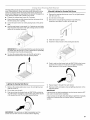
2. Lift out the searing side burner. 8. Open the manual shutoff valve in the gas supply line. The
valve is open when the handle is parallel to the gas pipe.
3. Locate the Liquid propane orifice at the end of the valve.
4.
A. Orifice
Use 6 mm socket wrench or 6 mm nut driver to remove the
orifice. Replace with the Natural gas orifice.
9.
A. Closed valve
B. Open valve
Test all connections using an approved noncorrosive leak-
detection solution. Bubbles will show a leak. Correct any leak
found.
Record Conversion
1. The appliance nameplate is located inside the grill cabinet on
the left-hand cabinet side. With a permanent marker, check
the box next to "Natural gas" and mark through "LP -
Propane."
In the last page of the Use and Care Guide, write "Converted to
Natural Gas." Also record the conversion date and the
technician/company that performed the conversion.
NOTE: Place LP gas parts in plastic parts bag for future use and
keep with pack containing literature.
Adjust High Flame Setting Screw
When converting from LP to Natural gas, you will need to adjust
the high flame setting screw for ideal burner flame height.
1. Pull out each control knob for the main burner and side
burner.
.......A
A. Orifice
IMPORTANT: Check that the orifice is properly installed
inside of the valve.
5. Reinstall the searing side burner. Make sure that the igniter is
out of the way to allow proper positioning of burner. Use
Phillips screwdriver to attach the mounting screws.
6. Use Phillips screwdriver to reattach the igniter and searing
side burner plate.
7. Reinstall searing side burner cover. Use Phillips screwdriver
to attach mounting screws.
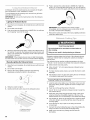
2.
3.
Use a flat-blade screwdriver to turn the high flame setscrew
counterclockwise approximate 90 °.
f
Check that burner operates at the new high flame setting. It
may be necessary to adjust the screw setting slightly more to
get the ideal burner flame height.
17

The burners are tested and factory-set for most efficient
operation. However, variations in gas supply and other conditions
may make minor adjustments to air shutter or low flame setting
necessary.
It is recommended that a qualified person make burner
adjustments.
NOTE: The rotisserie burner cannot be adjusted.
Checking and adjusting the grill burner flames requires removing
the grates and flame tamers.
Burner Flame Characteristics
6,
If flame is yellow (not enough air), turn air shutter adjustment
screw counterclockwise.
If flame is noisy or lifts away from burner (too much air), turn
air shutter adjustment screw clockwise.
A. Air shutter adjustment screw
The flames of the grill burners and side burners (on some models)
should be blue and stable with no excessive noise or lifting (LP
gas flames will have a slightly yellow tip). A yellow flame indicates
not enough air. If flame is noisy or lifts away from the burner, there
is too much air. Some yellow tips on flames when the burner is
set to HIGH setting are acceptable as long as no carbon or soot
deposits appear. The flames should be approximately 1" (2.5 cm)
high.
1"(2.5cm)
Check that burners are not blocked by dirt, debris, insect nests,
etc., and clean burners as necessary. If they are clean, adjust air
shutters as needed.
IMPORTANT: Before adjusting air shutters, let burners cool
completely.
To Adjust:
1. Light grill using information in the "Outdoor Grill Use" section.
2. Observe flame to determine which burners need adjustment
and how the flame is acting.
3. Turn off the valve and wait until grill and burners cool
completely.
4. _ove grill grates and flame tamers.
5. ,_:_4ove the 2 screws that hold the burner in place. Remove
gas burner from the grill.
7,
8.
Adjustment should be made clockwise or counterclockwise
from V8"(3.2 mm) to V4"(6.4 mm).
Replace gas burner, flame tamers and grates.
Light grill using information in the "Outdoor Grill Use" section.
See "Burner Flame Characteristics."
Low Flame Adjustment
If flame goes out on the "LOW" setting, the low flame setting
must be adjusted.
1. Turn off the valve and wait until grill and burners are cool.
2. Remove grill grates and flame tamers.
3. Light grill using information in the "Outdoor Grill Use" section.
4. Turn burner to its lowest setting.
5. Pull out each control knob for the main burner and side
burner.
6. Hold valve stem with pliers and insert a small flat-blade
screwdriver into the shaft.
7. Watch the flame and slowly turn the screwdriver
counterclockwise.
8. Adjust flame to minimum stable flame.
A. Screw
C
A. Valve stem
B. Smafl flat-blade screwdriver
C. Pliers
9. Replace the control knob and turn off the burner.
10. Repeat steps 3 through 9 for each burner if needed.
11. Replace the flame tamers and grates after the burners have
cooled.
18

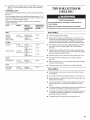
OUTDOOR GRILL USE
This manual covers several different models. The grill you have purchased may have some or all of the features listed. The locations and
appearances of the features shown here may not match those of your model.
Control Panel
©
BA C D G H
H
E F
A. Left grill burner knob
B. Left-center grill burner knob
C. Right-center grill burner knob
D. Rotisserie burner knob
E. Right grill burner knob
F. Grill fight switch
G. Control panel light switch
H. Searing side burner knob
E×plosion Hazard
Do not store fuel tank in a garage or indoors.
Do not store grill with fuel tank in a garage or indoors.
Failure to follow these instructions can result in death,
explosion, or fire.
Fire Hazard
Do not use grill near combustible materials.
Do not store combustible materials near grill.
Doing so can result in death or fire.
Food Poisoning Hazard
Do not let food sit for more than one hour before or
after cooking.
Doing so can result in food poisoning or sickness.
Inspect the LP Gas FuelTank Supply Hose
Inspect the gas pressure regulator/hose assembly before each
use.
1. Open left-hand cabinet door.
2. Inspect the gas pressure regulator/hose assembly for cuts,
abrasions, or excessive wear.
3. If necessary, replace the gas pressure regulator/hose
assembly before using the grill.
Contact the dealer and use only replacement hoses specified
for use with the grill.
A
A. Gas pressure regulator/hose assembly
19

Prepare the Grill for Lighting
1. Open the hood completely. Do not light burners with the hood
closed.
2. Make sure control knobs are turned to OFE The drip pan
must be in place and pushed all the way to the back.
\
A. Drip pan
Turn the Gas Supply On
1. For outdoor grills using a 20 Ib LP gas fuel tank:
Slowly open the tank valve.
NOTE: If flow limiting device activates, your grill may not
light. If your grill does light, the flames will be low and will not
heat properly. Turn tank valve and all control knobs off and
wait 30 seconds. After shutting off the tank, very slowly open
tank valve and wait 5 seconds before lighting.
2. For outdoor grills using gas supply source other than 20 Ib LP
gas fuel tank:
Open the manual shutoff valve in the gas supply line. The
valve is open when the handle is parallel to the gas pipe.
5. Repeat for each of the other burners as needed.
IMPORTANT: If burner does not light immediately, turn the
burner knob to OFF and wait 5 minutes before relighting.
Manually Lighting the Grill and Searing Side Burner
1. Open the hood completely. Do not light burners with the hood
closed.
2. Do not lean over the grill.
3. Remove the manual lighting extension (see following
illustration) and attach a match to the split ring.
0
4. Strike the match to light it.
5. Guide the lit match under the grill grate.
6. Push in and turn the burner knob to IGNITE HIGH for the
burner closest to the lit match. The burner will light
immediately. When burner is lit, turn knob to desired setting.
A. Closed valve
B. Open valve
Lighting the Grill and Searing Side Burner
IMPORTANT: If burner does not light immediately, turn the
burner knob to OFF and wait 5 minutes before relighting.
1. Open the hood completely. Do not light burners with the hood
closed.
2. Do not lean over the grill.
3. Select the burner you want to light. Push in and turn the grill
burner control knob to IGNITE HIGH, while continuing to hold
it in.
4. You will hear the "snapping" sound of the spark. When burner
is lit, release the knob. Turn knob to desired setting.
7. Repeat steps 2 through 6 for each main burner.
8. Remove match and replace manual lighting extension on the
right side panel.
IMPORTANT:
If burner does not light immediately, turn the burner knob to OFF
and wait 5 minutes before relighting.
If any burners do not light after attempting to light them manually,
contact the Customer Service Center. See the "Assistance"
section.
The grill must be plugged in for the hood lights to work. See
"Plug in Grill" in the "Freestanding Outdoor Grill Installation"
section.
To Use:
Press the LIGHTS button on the control panel to turn the hood
lights on and off.
20
Page is loading ...
Page is loading ...
Page is loading ...
Page is loading ...
Page is loading ...
Page is loading ...
Page is loading ...
Page is loading ...
Page is loading ...
Page is loading ...
Page is loading ...
Page is loading ...
Page is loading ...
-
 1
1
-
 2
2
-
 3
3
-
 4
4
-
 5
5
-
 6
6
-
 7
7
-
 8
8
-
 9
9
-
 10
10
-
 11
11
-
 12
12
-
 13
13
-
 14
14
-
 15
15
-
 16
16
-
 17
17
-
 18
18
-
 19
19
-
 20
20
-
 21
21
-
 22
22
-
 23
23
-
 24
24
-
 25
25
-
 26
26
-
 27
27
-
 28
28
-
 29
29
-
 30
30
-
 31
31
-
 32
32
-
 33
33


KitchenAid 720-0732 - Old Owner's manual
- Category
- Small kitchen appliances
- Type
- Owner's manual
- This manual is also suitable for
Ask a question and I''ll find the answer in the document
Finding information in a document is now easier with AI
Related papers
-
KitchenAid 720-0819G Owner's manual
-
-
-
KitchenAid 720-0745B User guide
-
-
-
-
KitchenAid 740-0781 Owner's manual
-
-
Other documents
-
 Nexgrill 710-0002 Owner's manual
-
 Kitchenaid - Old 740-0781 - Old Owner's manual
-
 Jenn Air - Old 720-0720 Owner's manual
-
 Surefire SF34LP User guide
-
Jenn-Air 720-0720 Owner's manual
-
Amana AM26LP-P Owner's manual
-
 Kirkland Signature 720-1068 Operating instructions
-
Jenn Air 730-0720 Owner's manual
-
Steba 18.70.00 Datasheet
-
RCS RSB3A Pro Burner Owner's manual


