Swegon CACA Operating instructions

Type
Operating instructions

This manual is also suitable for

GB.CACA.050101
Specifications are subject to alteration without notice. www.swegon.se 1
Compact Air room unit CACA-2-aa-bb
Size 08, 11
Language variant in display
Swedish
Norwegian
Danish = 21
Finnish
English
INSTALLATION AND MAINTENANCE INSTRUCTIONS
Congratulations on having selected
Compact Air!
To ensure that the time we spend
together will be agreeable, it is important
that you first read and understand these
instructions thoroughly.
Contents Page
1. General ........................................................ 1
2. Technical data .............................................. 2
3. Installation ................................................... 3
4. Description of the control system .................6
5. Commissioning ............................................ 9
6. Maintenance and servicing ......................... 12
7. Alarms and fault tracing ............................. 13
1. GENERAL
The Compact Air room unit is a complete air hand-
ling unit with supply air and exhaust air fans, supply
air and exhaust air filters, rotary heat recovery unit,
silencers and a built-in, low-momentum air diffuser.
The control equipment is also built-in.
Compact Air is well-suited for use in classrooms,
day nurseries, conference rooms, offices, working
premises, shops, restaurants and other similar public
premises.
Compact Air is available in two sizes: 08 and 11.
The unit is designed for installation in the room to be
ventilated and is connected to the mains by means
of a plug to an earthed wall socket. The ducts for
outdoor air and extract air can be connected to the
top of the unit and can be run through openings
in the wall.
The unit can be automatically controlled between
the normal flow and low flow rates by means of a
timer (switching clock) or presence detector (acces-
sories). Operational checks and temporary alteration
of the settings can be carried out in a control display
located on the front panel of the unit.
1.2 Specification
Whenever you get in touch with Swegon, please
refer to the production number found on the rating
plate inside the unit and the relevant product code(s)
according to the following:
Extra accessories
Presence detector CACZ-1-01
Electric air heater, 1 kW CACZ-1-02
Outer wall hood CACZ-1-03
7-day timer CACZ-1-05
Exhaust air connection CACZ-1-06
Infill piece against ceiling CACZ-1-07
Separate lower unit section CACZ-1-08
Air distribution plate CACZ-1-10-a
Variant 1, 2, 3, 4
UTELUFT
AVLUFT
FRÅNLUFT
TILLUFT
SUPPLY AIR
Supply air filter
Supply air fan
Outer wall hood
Silencer
Replacement filter
1 filter (class F85/EU7) CACZ-1-04-7
Low-momentum
air diffuser with
silencer
Exhaust air filter
Exhaust air fan
Heat recovery
unit
EXTRACT AIR
OUTDOOR AIR
EXHAUST
AIR
GB.CACA.050101
Specifications are subject to alteration without notice.
2 www.swegon.se
Sound eur level in dB(A) 1)
Static pressure Pa
Normal
Air flow installation
l/s (m3/h) 0-20 60 100 140
222 (800) 29 31 33
195 (700) 26 28 30 32
167 (600) 25 27 30 32
140 (500) 23 26 29
2.3 Sound
Sound pressure level values for different air flows and pressures
are tabulated below.
A normal installation including short outdoor air and extract air
ducts and an outer wall hood will generate a sound value tabu-
lated in the 0–20 Pa. column. Columns containing a dash are
irrelevant.
1) Indoors
The sound pressure levels tabulated above are applicable to a normal
day room, the reverberant field. The difference between the sound
power level and the sound pressure level (Lw – Lp) = 12 dB. If the
exhaust air connection accessory is used, sound pressure levels other
than those tabulated above may arise.
Outdoors
The sound pressure levels tabulated above are applicable to + 8 dB
at a distance of 10 metres from the outer wall hood. The difference
between the sound power level and the sound pressure level (L
w
– L
p
) = 25 dB.
Available pressure, Pa
Air flow, l/s
Example (broken line):
If an air flow of 250 l/s (900 m3/h) is required, the max.
permissible pressure drop (in connected ducts and air devices,
for instance) will be 90 Pa.
Air flow, m3/h
2.1 Capacity, air flows
The chart shows the available pressure over and above that of the
normal installation (short outdoor air and extract air ducts each
with its own 90° bend and common outer wall hood).
150
100 150
400 500 600
200
800700
100
50
0
125 175 225
Size 08
Available pressure, Pa
Air flow, l/s
Air flow, m3/h
Size 11
150
200
800 900 1000 1100
250
700
300
100
50
0
Size 08
Size 11
Sound prur level in dB(A) 1}
Static pressure Pa
Normal
Air flow installation
l/s (m3/h) 0-20 60 100 140
305 (1100) 34
250 (900) 30 32 34
195 (700) 26 28 30 32
2. TECHNICAL DATA
without air heater with air heater
Size active power current active power current
(W) (A) (W) (A)
08 480 3,3 1480 7,7
11 710 3,4 1710 7,8
2.4 Electrical data
Power is supplied by means of a plug to an earthed wall socket
for single-phase, 10 A, 230 V supply. The power demand at the
max. air flow rate is:
Example (broken line):
If an air flow of 167 l/s (600 m3/h) is required, the max.
permissible pressure drop (in connected ducts and air devices,
for instance) will be 140 Pa.
2.2 Comfort boundary
The air flow, room temperature and supply air temperature have
an influence on the comfort boundary of the unit (how near an air
device one can spend time without feeling a draught).
The velocity of the air diffused by the Compact Air diffuser is very
even and the normal comfort boundary from the surface of the
diffuser is about 1 metre.
GB.CACA.050101
Specifications are subject to alteration without notice. www.swegon.se 3
1090
120
32
654
226310
780
700
136
310190
1230
2088
858
Total weight: 300 kg. Upper section: 185 kg, lower section:
115 kg. Min. free space required for opening the inspection
door (left-hand hung) is 1100 mm.
Unit viewed from above.
EXTRACT AIR
Ø250
OUTDOOR AIR
Ø250
2.5 Dimensions and weights of the unit
165
440
680
cc 310
ø 250
185
171
2.6 Dimensions of the outer wall hood
(accessory)
The connections can
be reversed at the
building site.
3. INSTALLATION
3.1 General
The unit is delivered packaged, upright on a wooden pallet. The
kick-base is delivered as a kit, lying flat on the pallet below the
unit.
Accessories, if ordered, are delivered in unmounted condition
with the unit.
3.2 Transport at the building site
Compact Air is always supplied as one unit. If narrow passageways
at the building site make transport difficult, the upper and lower
unit sections can be separated as described below:
3.2.1 How to separate
the unit into
sections
to facilitate
transport at the
building site
EXHAUST AIR
The upper and
lower sections can
be separated for
transport att the
building site.
A: Open the inspection door by unscrewing the two Allen
screws on the front using the Allen key supplied.
B: Disconnect the connection cable of the display, pull out the
switch by the door, and loosen the door stop at one end.
C: Unscrew the two screws on the upper side of the hinge
on the inspection door while someone else is hol-
ding the door.
D: The door can now be lifted off.
E: Withdraw the supply air and exhaust air filters.
F: Withdraw the partitions above and below the heat exchan-
ger package.
G: Disconnect the connector of the heat exchanger drive
motor above/below the heat exchanger package and then
withdraw the heat exchanger.
H: Disengage the supply air sensor situated in the bottom of
the upper section and pull it straight up.
I: Disconnect the connector of the lower fan and then
unscrew the screw(s) on the front of the fan. The whole
fan package can now be pulled forward and lifted out.
J: Place the unit on its backside on a level surface.
K: Unscrew the 5 screws in the bottom of the upper section.
These hold the two sections together.
L: Now each section can be transported individually.
M: Reassembly can be carried out in the reverse order.
GB.CACA.050101
Specifications are subject to alteration without notice.
4 www.swegon.se
3.6 Outer wall hood
The CACZ-1-03 outer wall hood (accessory) is specially designed
for low pressure drops and for preventing short-circuiting between
the outdoor air and extract air. As standard, it is painted in a grey-
black shade, NCS 8502-B.
Assembly procedure:
1. The outer wall hood consists of a wall hood and front piece.
Begin by unscrewing the screws that secure the front piece to
the hood and remove the front piece. The wall hood can now be
used for checking the size of the openings and the position of
the connections.
2. Make openings in the wall and run the 250 mm dia. extract
air and outdoor air spiral ducts out through them. The duct ends
should be flush with the facade of the building. See Section 2.6
for the dimensions and arrangement of the openings.
The ducts should be insulated as described in Section 3.5 along
their entire length out to the facade. The gap between the wall
opening and the duct should be carefully sealed.
3. The wall hood has spigots fitted with a rubber seal ring for
connection to 250 mm dia. spiral ducts. Connect the wall hood
to the outdoor air and extract air ducts. At this stage, it does not
matter which duct is for outdoor air or extract air.
Secure the wall hood to the facade in a suitable manner. Seal the
joints with sealing compound or the like to prevent water from
seeping in.
4. Then secure the front piece by means of screws to the wall hood.
Note that the front piece can be reversed so that the extract air
outlet will be on the correct side. The extract air must always be
discharged straight out (horizontally) and admission of the outdoor
air must always be from below.
3.3 Location
To achieve the best possible operational economy, it is important
that the ducting system be designed so that the pressure drop will
be as low as possible. Strive to arrange runs of ducting that are
as short as possible and do not to include more bends than are
necessary. The arrangement of duct connections on the Compact
Air unit is such that the ducts can be run in any direction without
blocking one another.
The design of the hoods, grilles, etc. for outdoor air/extract air
are also important. The specially designed outer wall hood of the
Compact Air system is designed for minimising pressure losses.
The illustration below shows a few examples of alternative loca-
tions of Compact Air in a room.
From the standpoint of comfort, no working place should be
arranged closer than about 1 metre from the unit. However, bear
in mind that a minimum free space of 1100 mm is required for
opening the inspection door.
Examples of alternative locations of Compact Air in a room. The
ducting arrangement will be the simplest and shortest if the
room unit is located against an external wall.
3.4 To assemble the kick-base
Fasten 4 of the 6 screws supplied in the sheet metal pockets fitted
with nuts at the bottom of the short sides of the unit. Screw in
each screw halfway. Pull each screw first downwards and then
outwards until the sheet metal pocket with nut is 90° from its
original position.
Then fit the side kick-base plates (the 2 short plates). The ”key
holes” should point upwards and the nut should be against the
front edge of the unit. Fit the plates so that the key holes engage in
the screws and push the side plates as far as possible towards the
back edge of the unit (so that the key hole bottoms) and tighten
the screws using an Allen key through the pre-punched holes.
Then fit the last 2 screws in the front edge of the unit screwing
them only 1 or 2 turns (i.e., the screws far out). Hang the front of
the kick-base on the two screws. Then tighten the screws until the
front kick-base plate is hard up against to the side panels.
CAUTION! If the unit is to be located with its right or left side
directly against a wall, the side base plate towards this wall must
be fitted before the unit is installed at its location.
3.5 Duct connection
250 mm dia. spiral ducts for outdoor air and extract air can be
connected at the top of the unit.
The ducts should be run through openings in the external wall. If
a Swegon outer wall hood is to be fitted, the duct ends should be
flush with the facade.
Ducts can also be run through the ceiling. However, this will involve
a more complicated modification of the building and, among other
things, will place higher demands on weather sealing.
The ducts should be insulated with at least 30 mm thick insulation
backed with external moisture-tight foil.
Wall hood
Front piece
Inside Facade
Spiral tube
ends should
be flush
with the
facade.
AIR
External wall
Spiral tubes
with insulation
EXTRACT AIR
OU
TDO
OR
GB.CACA.050101
Specifications are subject to alteration without notice. www.swegon.se 5
3.8 Serving more than one room
Compact Air is designed for installation and connection in accor-
dance with the instructions in Sections 3.3, 3.5, 3.6.
Swegon recommends this precedure.
Nevertheless, it is possible to completely or partially extract exhaust
air from adjacent rooms or also to ventilate a space other than that
in which the unit is standing.
Typical problems, that can arise and should be noted, are given
below. A professional fitter should always be engaged to do the
work.
3.8.1 Pressure drop
The air flows specified are applicable to an installation arranged
against an external wall, i.e., with one 90° bend per duct and an
outer wall hood.
If a different ducting arrangement is used, it is advisable to make
sure that the pressure drop in the ducting will not be greater than
the available pressure specified in the charts, under ”Technical
data” in Section 2.
3.8.2 Exhaust air intake
If the exhaust air is extracted completely or partially from adjoining
rooms, the recommendations above should be noted taking into
account the pressure drop in the ducting.
It should also be noted that the supply air temperature is control-
led as a function of the exhaust air temperature. If the exhaust
air comes from another room having a dif-ferent temperature,
the temperature of the supply air may give rise to short-circuiting
or draught problems. Carefully consider where the exhaust air
sensor is situated.
3.8.3 Overflow air
Overflow air devices fitted between adjoining rooms have a strong
influence on how the system operates.
Overflow air devices located near floor level will cause ”unused”
air to be transferred to adjoining rooms and this will impair the
ventilation in the room in which the room unit is located.
Overflow air devices located near the ceiling entail the risk that
”used” air will be transferred to adjoining rooms. However, the
ventilation in the room in which the room unit is located, will not
be impaired. NOTE! If doors are left standing open, adjoining
rooms will also be ventilated due to the displacing action of the
air supplied.
3.7 Existing ventilation
The existing supply and exhaust air ventilation of the room shall be
blanked off or sealed. This is an important prerequisite for adequate
ventilation and heat recovery.
3.9 Electrical connection
3.9.1 Safety
The inspection door can only be opened with a special key. When
the door is opened, the power supply to the fans, the heat recovery
unit and the electric air heater will be automatically interrupted
by a limit switch.
NOTE! When the inspection door is opened, the control
equipment will still be energised!
3.9.2 Power
The unit is connected to the mains by means of a plug to an earthed
wall socket for a single-phase, 10 A, 230 V supply. The unit will
start automatically when the plug is connected, provided that the
inspection door is closed.
3.9.3 Control equipment
The connector of the 7-day timer or presence detector (accessories)
can be connected to a socket at the top of the unit as shown in
the figure below.
Instead of controlling by means of a presence detector or timer,
this can be done by means of a central timer. The conductors
from the central timer can be connected to the terminals shown
in the figure below. When the circuit is closed, the fans will run
at high speed.
3.9.4 Group alarm
A group alarm can be connected via the output terminals on the
control card to an alarm distribution box (see the circuit diagram
on page 8).
3.9.5 Electric air heater
If an electric air heater has been ordered as accessory, it has been
delivered separately and should be fitted at the site according to
the special instructions included.
The air heater has a factory-wired connector for connection to a
socket in the unit.
CAUTION! A min. permissible airflow of 111 l/s (400m3/h) is
applicable to ventilation systems in which an in-duct electric air
heater is installed.
-+
12 V DC
C-ur
7-day timer/
Presence-
detector
Ev. central-
timer
GB.CACA.050101
Specifications are subject to alteration without notice.
6 www.swegon.se
4.3 Temperature control
4.3.1 Control sequence
When heating is required, first, the speed of the heat recovery
rotor will increase. Then the electric air heater, if fitted, will
begin to pulsate output. If no electric air heater is installed,
or if the air heater output proves inadequate, the speed of
the supply air fan will be slightly decreased so that the correct
temperature will be obtained.
4.3.2 ERS control
Compact Air operates on the principle of ERS control (exhaust
air temperature-related supply air temperature control). This
means that the supply air temperature is controlled in relation
to the exhaust air temperature.
This type of temperature control offers optimum operational
economy and heat recovery, and eliminates the need of any
reheater.
Compact Air offers two options for controlling the supply air
temperature: Either according to Section 4.3.3 so that it follows
the exhaust air temperature or according to Section 4.3.4 so
that its operation maintains the desired room temperature if
the temperature of the exhaust air is high.
4.3.3 Supply air temperature
The supply air temperature is controlled in relation to the
exhaust air temperature.
Control can be carried out according to one of three alternative
steps.
Step 1 offers the best operational economy and cooling capa-
city in warm rooms, however steps 2 and 3 may be necessary
in day nurseries, for instance, where children often spend time
at floor level.
Provision is available for presetting the min. supply air
temperature. If the supply air temperature is below the min.
preset value for more than 5 minutes, the unit will be shut
down for one hour.
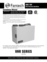
The difference between the three steps is illustrated in the
chart below.
15 16 17 18 19 20 21 22 23 24 25 26 27 28 29 30 31 32
15
16
17
18
19
20
21
22
23
24
14
Supply air temperature °C
Exhaust air temperature °C
The plotted broken lines show the difference between steps 1 and 3
at a given exhaust air temperature (23 °C).Step 1 gives a supply air
temperature of 18.8 °C and step 3 gives 21 °C.
4. DESCRIPTION OF
CONTROL SYSTEM
4.1 General
The settings that can be entered and the effect of various
control functions of the Compact Air unit are described in this
section. A diagrammatic presentation of the functional princi-
ple and a circuit diagram are also included.
The procedure for entering the various settings is described
in section 5.
4.2 The air flows
When air flow settings are preset, these settings affect both
the supply air flows and the exhaust air flows at the same
time and automatically. Whenever a flow setting is altered, it
will take about 1 minute for the fans to change over to the
new speed.
The air flows can be preset as follows:
Size 8
Normal air flow, variable from 83–222 l/s (300–800 m3/h). Low air
flow, switched off or variable from 83–222 l/s (300–800 m3/h).
Size 11
Normal air flow setting, variable from 83–305 l/s (300–1100
m3/h)
Low air flow setting, switched off or variable from 83–305 l/s
(300–1100 m
3
/h).
NOTE! Normal air flow can not be selected at a lower rate than
low flow.
4.2.1 Normal flow
The air flow is preset taking into account the size of the room
and the activity pursued. It should be noted that the cooling
effect will be better, the higher the air flow rate is.
4.2.2 Low flow
Walls, furniture, carpeting etc. often also emit contaminants.
Therefore, continuous ventilation is important, even if to a
lesser extent when the premises is not being used. Swegon
recommends pre-setting the low air flow rate so that it cor-
responds to at least 1 air change per hour.
The unit can be switched off during the period otherwise
reserved for low flow, but this is not recommended.
Every time the 7-day timer or presence detector switches the unit
from normal flow to low flow operation, a filter test will be auto-
matically carried out. During this test, the unit will some-times run
at an air flow rate other than the preset flow rate.
4.2.3 Airing
This function causes the unit to run at maximum air flow
with reduced supply air temperature (set point: 10°C) for 15
minutes.
The airing function can be selected manually in the control display. If
a presence detector is used to control the unit, the automatic airing
function can be selected.
One condition for automatic airing is that the unit must have opera-
ted at normal air flow for at least 10 minutes (i.e. the detector must
have registered the presence of one or more occupants) and after
that, not registered any presence for 5 minutes.
Step 3
Step 2
Step 1
GB.CACA.050101
Specifications are subject to alteration without notice. www.swegon.se 7
4.3.4 Room temperature
If control of the supply air temperature according to 4.3.3
does not produce adequate cooling effect, control of the room
temperature may be selected as an alternative.
If this alternative is selected, the supply air temperature will
instead be controlled in such a way that the unit will try to
maintain the required room temperature with the following
reservations:
1. The temperature of the air supplied by the Compact Air unit
will never be higher than the temperature in the room.
2. The temperature of the air supplied by the Compact Air unit
will never be lower than the temperature of the outdoor
air.
3. The required room temperature can be programmed in
increments of 1 °C within a 19–24 °C interval.
The lowest permissible supply air temperature can be program-
med in increments of 1 °C within a 15–19 °C interval,
however it must be at least lower than the required room
temperature. Setting the lowest permissible supply air tempe-
rature will only have effect if the room temperature is within
the 19–24 °C interval.
Provision is available for presetting the min. supply air
temperature. If the supply air temperature is below the min.
preset value for more than 5 minutes, the unit will be shut
down for one hour.
Note that this type of control may get into conflict with the
heating system of the room. This means that there should be
adequate difference between the room temperature
selected for the unit and the room temperature set point of
the heating system.
The plotted broken line shows how the supply air temperature
varies, conditional to the exhaust air temperature if the room
temperature is preset to 21 °C and the lowest supply air
temperature to 16 °C.
Exhaust air temperature °C
Supply air temperature °C
Room temp. 19-24°C
Min.. supply air temp. 15-19°C
4.3.5 Summer night cooling
The summer night cooling function is a simple method used
for supplying cool outdoor air to the premises under summer
conditions.
Within specific temperature limits, the Compact Air unit will
automatically run at normal air flow and the supply air tempe-
rature set point will be set to the preset MIN SA TEMP.
Conditions under which summer night cooling should
be activated:
The function has been selected (1) in the settings
menu.
The unit has been running at the low flow setting for
one hour.
The mean outdoor temperature should be above the
preset OUTDOOR value (factory-preset to 10°C).
The exhaust air temperature should be above the
preset EA value (factory-preset to 24°C) .
No heating demand should have been called for during
the most recent period when the fan was running at high
speed.
The temperature differential between the exhaust air
and the outdoor air should be at least 3°C.
If all the conditions other than that of the temperature dif-
ferential between the exhaust air and the outdoor air are
satisfied, an attempt at restarting the unit will be made at one
hour intervals.
If any of the other conditions have not been satisfied when a
test is carried out, the function will be interrupted and it will
not be possible to start it until after the next normal air flow
period.
In those cases in which the unit is set to LOW FLOW = 0, the
fans will run at the normal air flow rate during the preset
period displayed under TIME (factory-preset to 3 min.). The
reason for this is to enable the temperature sensors to register
measurements under the right conditions.
Conditions under which the function should be deacti-
vated:
The exhaust air temperature falls below the preset
OUTDOOR value (factory-preset to 10°C).
The exhaust air temperature is lower than the preset
EA STOP value (factory-preset to 18°C).
The timer or presence detector is activating normal
flow.
The display is being manually controlled.
GB.CACA.050101
Specifications are subject to alteration without notice.
8 www.swegon.se
4.4 External control
4.4.1 7-day timer (switch clock)
The 7-day timer controls the unit, switching between normal flow
and low flow operation. The required times for switching between
low flow and normal flow can be individually preset for the dif-
ferent days of the week.
Swegon recommends low flow when the premises is not being
used, for example at night-time and on weekends.
NOTE! The unit will run at low flow when the 7-day timer indicates
OFF, and at normal flow when the timer indicates ON.
4.4.2 Central timer
As an alternative to using a 7-day timer, the unit can be controlled
by means of a central timer.
4.4.3 Presence sensor
The presence detector is a type of motion detector which reacts
to infrared light.
The unit will run at low air flow as long as the detector does not
register the presence of any occupants in the room. As soon as
presence is registered, the unit will be controlled to normal flow.
When the room is vacant again, the unit will return to low flow
operation, but not immediately. It will continue running at the
normal flow rate:
for 5 minutes if the unit has run at normal flow for less than
10 minutes,
for 20 minutes if the unit has run at normal flow for more than
10 minutes.
The automatic airing function may be preset in conjunction with
the use of a presence detector.
4.5 Duct pressure drop calibration
Calibration of the pressure drop in the ducting should be carried
out in conjunction with commissioning the unit after installa-
tion.
The calibration stores information about initial operating condi-
tions when clean filters are fitted and the duct system is connected.
The control equipment saves this basic information and later com-
pares it with the current operating conditions. As the filter becomes
fouled, the pressure drop across them will increase. By comparing
the initial conditions with current conditions, the control equip-
ment can indicate when it is time to change the filters.
When the duct pressure drop calibration function is activated, the
unit will let the fans run for about 30 minutes in order to warm
up the motor windings, etc. The calibration will then be carried
out and information about the current operating conditions will
be stored in the memory. After that, the unit will resume normal
operation.
In the event of a power failure after completed calibration, the
control equipment will retain the calibration data stored in its
memory.
4.6 Rotation detector test
A rotation detector test will be carried out when the unit has been
switched from normal flow (HF) to low flow operation and the
heat exchanger has been controlled to run at 100% efficiency.
While the rotation detector test is in progress, a message to this
effect will appear in the display.
The rotation detector test is carried out for testing the efficiency of
the heat exchanger. The rotational speed of the rotor is decelerated
until the rotor stops and the temperature readings from the supply
air sensor are analysed. If the temperature falls as the readings are
registered, the rotor is operating properly.
GB.CACA.050101
Specifications are subject to alteration without notice. www.swegon.se 9
4.7 Filter test
The filter test will be carried out when the unit has been swit-
ched from normal flow (HF) to low flow operation. The test will
then be carried out only once during a 12 hour interval. If no
switch-over from normal flow to low flow is called for, the filter
test will be carried out once every 24-hour period. While the
filter test is in progress, a message to this effect will appear in
the display.
As the filters become fouled the pressure drop across them will
increase. By comparing the initial conditions with current con-
ditions, the control equipment is able indicate when it is time
to change the filters. Whenever the alarm limit for the pressure
drop across the filter has been exceeded, an alarm indication
will appear in the control display.
4.8 Automatic fan adjustment
Compact Air employs self-adjustment of the speed of the fans for
maintaining the preset air flow rate.
A pressure rise in the system, due to clogged filters, for instance,
will always be compensated automatically so that the preset air
flow will always be obtained.
4.9 Alarms
Besides the alarm for necessary filter change, alarms are also ini-
tiated for any functional faults.
The alarms are indicated by a flashing red lamp and a message in
plain text in the control display.
A group alarm can be connected to terminals in the alarm dist-
ribution box.
EXHAUST AIR
EXTRACT AIR
OUTDOOR AIR
SUPPLY AIR
Temperature sensor
Filter
Rotary heat
exchanger
Turbo
El. heater
(accessory)
Supply
fan
Silencer
Temperature sensor
Temperature
sensor
Silencer
Filter
Supply diffusor
4.11 Circuit diagram
4.10 Functional principle
M
N
L
M
M
N
L
N
L
L3
L2
L1
1
2
3
4
5
6
7
8
9
10
11
12
13
+5V
14
15
16
17
+12V DC
18
19
20
21
22
23
GT1
24
25
GT3
26
27
GT2
Swegon
403851-01A
N
L
L L
N N
N
L
DOOR
BREAKER
EXHAUST AIR FAN
HEAT
EXCH.
Blue
Yellow/green
Brown
HEAT EXCH.
MOTOR
Grey
White TACHO
SUPPLY AIR FAN
SUPPLY
AIR FAN
EL.
HEATER
ELECTRICAL HEATER
ALARM
SUM-
ALARM
Brown
White
Yellow
Green
Green
Yellow
Brown
White
DISPLAY
SWITCHING
CLOCK/
PRESENCE
SENSOR
Indication 0-10 V DC =
flow 0-1200 m3/H
SA 0-10V
EA 0-10V
SA
EA
Outdoor air
Exhaust air
Supply air
Brown
Blue
Brown
Blue
Brown
Blue
Brown
White
Yellow
Green
GB.CACA.050101
Specifications are subject to alteration without notice.
10 www.swegon.se
When the PROG button is depressed, the PROG text will change
to SET and LOW FLOW will start to flash. Select higher or lower
flow values by pressing or until the required
flow is displayed. Then press SET to enter the setting. NORM
FLOW will now start to flash. This setting can be altered in the
same way as that of LOW FLOW. When the correct flow is indica-
ted, press SET. Then press to continue to the next display.
The type of control and whether summer night cooling function
is desired can be selected in the display below.
If required, the supply air regulation STEP number can be altered by
pressing the PROG button. SA REG will then start to flash. Select
the step number by pressing or until the required step
number is displayed. Then press SET. Summer night cooling will start
to flash after the control setting has been altered. Select ”on(1) or
”off” (0) by pressing or . Then press SET.
5.2 To enter settings
To gain access to the settings menus, open the inspection door.
When the alarm text shown in Display 3 appears, press the RES
(reset) button.
Display 4 will then appear. From this display, it will be possible to
enter settings and go on to other menus.
A technical description of settings and functions are given
in Section 4.
If low flow or norm flow need not be altered, press and the
next display will appear.
If low flow or norm flow is to be altered, press PROG.
5. COMMISSIONING
5.1 General
Insert the plug in the wall socket. The following message will
appear in the display:
*** PROGRAM RHX ***
LOW FLOW 350 m3/h
NORMAL FLOW 950 m3/h
PROG
When the message above is displayed, you may go on through
the menus and enter settings. See Section 5.2.
*** ALARM 01 ***
POWER SUPPLY TO
MOTORS INTERRUPTED
RES
Display 3.
Depending on the settings entered, NORMAL FLOW may appear
in the display instead of LOW FLOW.
If the door is open the following message will appear:
*** COMPACT AIR 2 - xx ***
NORMAL FLOW
+ AIRG
If the language desired has already been preset, press OK. If
another language is desired, see under section 5.2 ”Entering
settings”.
If the inspection door of the unit is closed and no faults have arisen,
the message below will appear.
SPRÅK / LANGUAGE
ENGLISH
Display 1.
Display 2.
SA REG STEP 1
SUMMER NIGHT COOL 0
PROG
Display 4.
Display 4.
OK
GB.CACA.050101
Specifications are subject to alteration without notice. www.swegon.se 11
When the unit has been connected to the ducting for the first
time, a DUCT CALIBRATION must always be carried out.
Select duct calibration by pressing PROG and alter the 0 to 1
by
pressing or . Then press SET.
The duct calibration will be carried out automatically by the unit
as soon as the inspection door has been closed. The unit makes a
check to determine that the fans have been running for at least 30
minutes before the calibration starts. The calibration takes about
3 minutes. During this period, the unit must be left untouched.
FILTER TEST/DUCT CALIBRATION will flash in the display while
calibration is in progress.
The MIN SA TEMP function is entered as a lower limit for the supply
air temperature set point.
If the supply air temperature falls, the supply air set point will
drop to the preset MIN SA TEMP at the most. If the supply air
temperature drops below the preset MIN SA TEMP for more than
5 minutes, the unit will shut down. An attempt to restart the unit
will take place once every hour until the operating conditions
have been satisfied.
Select MIN SA TEMP by pressing . Press PROG. Select
values by pressing or . Press SET.
Continue by pressing .
The type of accessories connected and the automatic airing option
appear in this display. Press PROG to alter the settings. The flashing
text can be altered by pressing or . When all the set-
tings have been entered, press SET.
1 = yes, 0 = no, apply to all the settings in this display.
TIMER = 7-day timer
PR DET = Presence detector
AIRING = Automatic airing
EL HEAT = Electric air heater.
If, on the other hand, supply air regulation is required, press SA
and the foregoing display will appear.
Then press to go on to the next display.
Display 6.
Select the required room temperature by pressing or and
press SET. ROOM REG MIN will then flash. Select the temperature
by pressing or and then press SET. Summer
night cooling will then start to flash. Select ”on” (1) or ”off” (0)
by pressing or . Then press SET.
If it is desirable to change from supply air control to room air
control, press PROG and then ROOM. The following display will
appear:
ROOM TEMPERATURE 22 °C
ROOM REG MIN 16°C
SUMMER NIGHT COOL 0
SA SET
Display 8.
Press to go on to the next display.
TIMER 0 PR DET 1
AIRING 0
EL HEAT 0
PROG
Display 7.
DUCT CALIBRATION 0
MIN SA TEMP °C
REG SPEED 0
PROG
Display 9.
To change language, press PROG. Select the language desired from
the five options in the display by pressing or . When the
appropriate language appears in the display, press SET.
The procedure for entering settings is now completed.
Should the need arise for entering additional settings afterwards,
the user need only open the inspection door and enter the instal-
lation menu by pressing RES.
*** COMPACT AIR " - xx ***
SPRÅK / LANGUAGE
ENGLISH
 
PROG
GB.CACA.050101
Specifications are subject to alteration without notice.
12 www.swegon.se
5.3.1 Normal operation
After the settings have been entered as described in Section 5.2,
the Compact Air unit will operate auto-matically. However, if
special neededs arise, the air flow can be altered temporarily, for
example if the premises is to be used one evening and the timer
has controlled the unit to operate at low flow.
All temporary alterations made will automatically change back to
the previous settings after a given period.
The text shown in Display 10 indicates the current type of ope-
ration — for instance NORMAL FLOW, LOW FLOW, LOW FLOW
= STOP, SUMMER NIGHT COOLING, etc.
5.3 Operation
Display 11 — Temporarily altered setting Display 12 — Airing
5.3.2 To temporarily alter the air ow setting
To temporarily alter the air flow setting (1 hour) press or + when
the text shown in Display 10 appears. The display will then change
as shown in Display 11.
FLOW: Press – to lower and + to temporarily increase the relevant
flow. Each square represents approx. 28 l/s (100 m3/h).
NORM: Shows normal operation, i.e.,the flow at which the unit ran
on transition from Display 10 to Display 11. Each square represents
approx. 28 l/s (100 m3/h).
TIME: Indicates the time that remains before the temporarily alte-
red flow setting will change back to normal operation. Each
square represents approx. 6 minutes.
When the last square after TIME disappears or when NORM
is pressed the unit will change back to normal operation and
Display 10 will reappear in the display.
5.3.3 Airing
To set manual airing (max. flow for 15 minutes) press AIRG when
the text in Display 10 appears. The display will then change to that
shown in Display 12.
TIME. shows the time remaining for airing at max. flow before
return to normal operation. Each square represents approx. 1
minute.
When the last square at TIME disappears, or if NORM is pressed,
the unit will return to normal operation and Display 10 will reap-
pear in the display.
Display 10 — Normal operation
*** COMPACT AIR 2 - xx ***
NORMAL FLOW
+ AIRG
+ NORM
FLOW
NORM
TIME
+ NORM
*** AIRING ***
TIME
GB.CACA.050101
Specifications are subject to alteration without notice. www.swegon.se 13
6. MAINTENANCE AND SERVICING
6.1 Filter change
Every time the unit is switched from normal flow to low flow, an
automatic filter test will be carried out. While this test is carried
out, the fans in the unit will sometimes run at a speed generating
a flow other than the preset flow.
When the filters need to be changed, an alarm indication will
appear in plain text in the control display. Open the inspection door
and withdraw the filters straight out. The filters are disposable and
must be replaced by new ones.
Duct calibration shall always be carried out when replacing filter.
6.2.4 Silencer and supply air diffuser
If the filter changes are carried out at normal service intervals,
fouling of the lower unit section with silencer and air diffuser will
be minimal. Should the lower unit section nevertheless require
cleaning despite regular filter changes, this can be carried out as
follows:
1. Remove the perforated front panel by unscrewing the four
screws located inside the perforations at each corner.
2. Remove the two screws located at the lower edge of the diffuser
panel as shown in the sketch below.
3. Press the diffuser panel downwards so that its upper edge
disengages from the screws in the ”key holes”.
4. Withdraw the diffuser panel pulling it forward.
5. The silencer baffle elements can be loosened by unscrewing
the locking screws in the sides at the rounded edge as shown
in the sketch below.
6. Note that each baffle element has a guide slot on each side and
must be slipped off the retaining pins that hold them in place,
as shown in the sketch below.
Reassembly can be carried out in the reverse order.
The most suitable way of removing dust is by vacuum cleaning.
Snitt från sidan
25
6
6.2.3 Fans
The fans are secured by means of screws. These must be removed
before dismantling. When the connectors have been disconnec-
ted, the fans can be withdrawn from the unit.
The fans can be cleaned by vacuum cleaning. Remove any deposits
from the impeller blades. Check the fan impellers to make sure
that they are not out of balance.
The fan motor should be vacuum cleaned or brushed off. It can
also be cleaned by carefully wiping it using a moist cloth dipped
in water and dish-washing detergent.
Supply air diffuser/silencer viewed from the side.
1 filter (class F85/EU7) CACZ-1-04-7
Replacement filters can be ordered from Swegon Service and
should be specified as follows:
TILLUFT
6.2 Cleaning
6.2.1 General
The interior surfaces of the unit should be cleaned, if needed. An
inspection should be carried out in conjunction with changing the
filter or at least twice a year.
6.2.2 Heat recovery unit
The heat exchanger can be removed from the unit by disconnecting
the electrical connector and withdrawing the whole rotor package.
If the rotary heat exchanger is vacuum cleaned, a soft nozzle should
be used to prevent damage to the air passages of the rotor. If the
rotor is severely fouled, compressed air may be used to blow the
passages clean. Water, a degreasing agent or solvent may also be
used for cleaning, after which the rotor should be blown clean
with compressed air.
Make sure that the type of solvent used does not have a corrosive
effect on aluminium!
Swegon detergent is recommended and is sold by Swegon
Service.
After cleaning, check that the drive belt of the heat exchanger runs
faultlessly on the motor pulley and around the heat exchanger
rotor.
GB.CACA.050101
Specifications are subject to alteration without notice.
14 www.swegon.se
7. ALARMS AND FAULT TRACING
7.1 General
When an alarm is initiated, a red lamp will flash and the fault will
appear in plain text in the display.
Should an alarm indication appear, act as follows:
1. Read the alarm number and text in display.
2. Seek out the alarm number and text in the list below, and
read the probable cause of the alarm and how the fault
should be remedied.
3. Correct the fault.
4. Reset the alarm by pressing ”RES” and the unit will resume
normal operation if no fault remains.
+ RES
*** ALARM 7 ***
EXH AIR FILTER
FOULED
Typical alarm
7.2 Alarm list
Alarm no 1.
POWER SUPPLY TO THE MOTORS INTERRUPTED
Cause: The power supply to the motors has been interrupted.
This occurs when the door switch is not pressed in or if
the control card is faulty.
Action: Close the door properly or adjust its retaining screw so
that it will close the switch when the door is closed. If
this does not help, get in touch with service personal.
Alarm no 2.
COMMUNICATION WITH SENSORS BROKEN
Cause: Faulty control card.
Action:
Get in touch with a service technician or qualified electrician to
check the card and replace any faulty component.
Alarm no 3.
SUPPLY AIR SENSOR FAULTY
Cause:
The signal level from the supply air sensor to the control card
is outside the reasonable temperature range.
Action: Get in touch with a service technician or qualified elec-
trician for measurements and to check the sensor.
Alarm no 4.
EXHAUST AIR SENSOR FAULTY
Cause:
The signal level from the exhaust air sensor to the control
card is outside the reasonable temperature range.
Action: Get in touch with a service technician or qualified elec-
trician for measurements and to check the sensor.
Alarm no 5.
OUTDOOR TEMPERATURE SENSOR FAULTY
Cause:
The signal level from the outdoor temperature sensor to the
control card is outside the reasonable temperature range.
Action: Get in touch with a service technician or qualified elec-
trician for measurements and to check the sensor.
Alarm no 6.
SUPPLY AIR FILTER FOULED
Cause: Alarm limit for filter pressure drop has been exceeded.
Action: Change the filter.
Alarm no 7.
EXHAUST AIR FILTER FOULED
Cause: Alarm limit for filter pressure drop has been exceeded.
Action: Change the filter.
Alarm no 8.
SUPPLY AIR TEMP. BELOW THE SET POINT
Cause. The supply air temperature has been more than 5°C
below the set point for more than 20 minutes.
Action: Check that the drive belt of the heat exchanger is tensio-
ned and does not slip on the drive pulley.
Alarm no 9.
SUPPLY AIR TEMP. BELOW THE ALARM LIMIT
Cause: The supply air temperature has been below the min.
limit (factory-preset to 6°C) for more than 20 minu- tes.
Action: Check the heating system in the room in which the unit
is standing so that the room temperature will not be too
low.
GB.CACA.050101
Specifications are subject to alteration without notice. www.swegon.se 15
Alarm no 10.
SUPPLY AIR FAN MOTOR FAULTY
Cause: The power supply to the motor has been inter-
rupted.
Action: Check that the connector of the motor is connected.
The internal temp. protection may have tripped. Get in touch
with a service technician or qualified electrician to check the
motor.
Alarm no 11.
EXHAUST AIR FAN MOTOR FAULTY
Cause: The power supply to the motor has been inter-
rupted.
Action: Check that the connector of the motor is connected.
The internal temp. protection may have tripped. Get in touch
with a service technician or qualified electrician to check the
motor.
Alarm no 12.
HEAT EXCH. MOTOR FAULTY
Cause: The power supply to the motor has been inter-
rupted.
Action: Check that the connector of the motor is connected.
Get in touch with a service technician or qualified electri-
cian to check the motor.
Alarm no 13.
ELECTRIC AIR HEATER FAULTY
Cause: The power is not being supplied to the electric air
heater.
Action: Check that the connector of the electric air heater.
Reset the overheating protection by pressing the reset
button on the air heater. An alarm will also be initiated if an
electric air heater is not installed but nevertheless has been
selected in the installation menu. If this is the case, omit the
electric air heater option from the menu.
Alarm no 14.
HEAT EXCH. SPEED MONITOR TRIPPED
Cause: The heat exchanger rotor fails to rotate.
Action: Check that the connector of the motor is connected,
that the drive belt is intact and that the rotor rotates freely.
Get in touch with a service technician or qualified electri-
cian to check the motor.
  • Page 1 1
  • Page 2 2
  • Page 3 3
  • Page 4 4
  • Page 5 5
  • Page 6 6
  • Page 7 7
  • Page 8 8
  • Page 9 9
  • Page 10 10
  • Page 11 11
  • Page 12 12
  • Page 13 13
  • Page 14 14
  • Page 15 15

Swegon CACA Operating instructions

Type
Operating instructions
This manual is also suitable for

Ask a question and I''ll find the answer in the document

Finding information in a document is now easier with AI