
User Manual PROBA 50 - English Doc.no.: 951573
Version: V1.3
Software: 000498 PROBA50 Version: V1.05
File: DO951573.HND
By: AAD Date: 07-03-2012
VDH Products BV - Roden - Holland Signed: Pages: 26
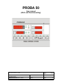
PROBA 50
User manual
(Wall- and Panel-mounting)

VDH Products BV Document 951573 - Version 1.3 Blad: 2 of 26
Disclaimer
The information contained in this document is assumed to be accurate. However VDH Products BV accepts no liability for
eventual mistakes or errors and has the right to change this document without notice.
Copyright Notice
Copyright 1995 VDH Products BV, Roden The Netherlands.
No part of this document may be reproduced without the prior written permission of VDH Products BV.
Trademarks
'PROBA' is a trademark of VDH Products BV.
Edition
3st edition, March 2012
It is highly recommended to study the operation
of the PROBA ripening system carefully before
using it.

VDH Products BV Document 951573 - Version 1.3 Blad: 3 of 26
Table of contents
1Introduction ................................................................................. 4
1.1 Setup of the PROBA ripening system ..................................................... 4
1.2 Operation of the PROBA ripening system .................................................. 4
1.3 Method of temperature control ........................................................... 5
2The PROBA 50 .............................................................................. 5
2.1 Control of the PROBA 50 ............................................................... 5
2.1.1 Switching the PROBA 50 ON and OFF ............................................ 5
2.1.2 Readout temperature, clock, sensors and setpoints .................................. 6
2.1.3 Programming and starting a ripening program ....................................... 6
2.1.4 Stopping a ripening program .................................................... 8
2.1.5 Changing the temperature setpoint ............................................... 8
2.1.6 Standby .................................................................... 9
2.1.7 Starting and stopping the gassing ................................................ 9
2.1.8 Starting and stopping the ventilation ............................................. 10
2.1.9 Stepping a program .......................................................... 11
2.1.10 Heating on/off switch ......................................................... 11
2.1.11 Switching sensors on/off ....................................................... 12
2.2 Adjustment of the PROBA50 ........................................................... 13
2.3 Regulation characteristics of the PROBA 50 ............................................... 14
2.4 Alarms and warnings of the PROBA 50 ................................................... 15
2.5 Error messages ..................................................................... 16
3 Datalogger ................................................................................. 17
Appendix A (Error messages) ......................................................................... 18
Appendix B (Internal Parameters) ...................................................................... 19
Appendix C (Technical Specifications) ................................................................... 21
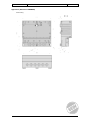
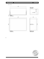
Appendix D (Frontview PROBA50) ..................................................................... 22
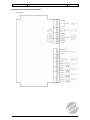
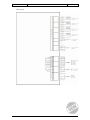
Appendix E (Connection diagram PROBA50) ............................................................. 23
Appendix F (Dimensions PROBA50) .................................................................... 25

VDH Products BV Document 951573 - Version 1.3 Blad: 4 of 26
1 Introduction
1.1 Setup of the PROBA ripening system
The PROBA 50 Ripening System provides a solution for the automated ripening of bananas. The system measures
and controls independently the temperature in the ripening room. Ventilation of the bananas is also controlled by the
system.
During a period of several days the system is capable of controlling one or more ripening rooms in such a way that
the fruit can be removed perfectly ripened from the rooms at the end of the ripening cycle.
The ripening room is fully controlled by the PROBA 50 computer. This steps through a ripening program
independently and can be controlled by the user via the front panel.
1.2 Operation of the PROBA ripening system
Bananas in the ripening room are ripened by means of ripening programs. In the PROBA ripening system the length
of these programs and the temperatures are adjusted each day. The ripener can make a choice from 10 different
ripening programs in each PROBA 50.
The course of the temperature is setup by means of temperature setpoints, one for each day. During the execution of
the program the temperature is checked and controlled by the PROBA 50 in such a way that the fruit is ripened
according to the requirements of the user.
The PROBA 50 is also able to control the application of gas during the ripening program. The duration of the
gasification is adjustable. During this period the PROBA 50 will indicate that gas is present in the ripening room.
During the ripening process the bananas can be ventilated. The length and interval of the ventilation are adjustable.
During gassing periods the ventilation is blocked. The PROBA 50 indicates when the room is being ventilated.
At the end of a ripening program the PROBA 50 switches over to the so-called STANDBY mode. The temperature
regulation continues on the STANDBY setpoint which ensures that the ripened product remains in a controlled
environment.
At any moment during the ripening program the temperature setpoint, which is used by the PROBA 50 at that
moment, can be changed (when the LED above the KEY button is on). The ripening program can also be changed
into STANDBY mode or stopped anytime by the user.
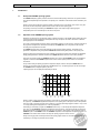
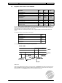
A ripening program can be displayed schematically as follows:
During a number of days (the length of the program, in this case is 4) a temperature setpoint is entered for each day.
On a given day, the PROBA 50 regulates the temperature in the ripening room to be equal or close to that particular
value. The length of a ripening program can be varied from 4 to 8 days (fixed length program numbers 1 to 5) or from
1 to 9 days (the length of the programs 6 to 10 are fully adjustable).
After setting up and starting a program the PROBA 50 starts at day 1. In the example the temperature setpoint is
now 18.0C, so the PROBA 50 regulates the temperature to become 18.0C. At the end of each day (24 hours) the
temperature setpoint is changed into that of the next day of the program. After all days of the program are past, the
PROBA 50 goes to the STANDBY mode. The STANDBY temperature is also adjusted in the ripening program. The
STANDBY mode remains active until the user stops the ripening program or starts a new one.
Finally a warming-up phase can take place before the ripening program starts. For convenience this precursion time
is called day 0. The length of precursion time is variable.

VDH Products BV Document 951573 - Version 1.3 Blad: 5 of 26
1.3 Method of temperature control
Up to four temperature sensors can be connected to the PROBA 50.
It makes use of three product sensors which are placed in the boxes with the bananas (pulp temperature). These are
the product sensors type SM8500 which are connected via the coiled leads to the connection boxes. The
temperature is controlled on the average of the present and active product sensors.
In addition, an air temperature alarm sensor, type SM8000/2m, can be connected. This sensor controls the minimum
and maximum temperature of the airflow coming out of the evaporator. The evaporator can be temporarily switched
off if the alarm levels are exceeded.
Via a setting in the internal parameters the method of control can be selected, at which product sensor 3 is replaced
by an air temperature sensor type SM800/2m. During the warming-up phase (day 0) the temperature is controlled by
sensor 3. When the warming-up phase is passed, the temperature is controlled on the average of sensor 1 and 2.
2The PROBA 50
2.1 Control of the PROBA 50
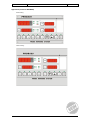
The control computer PROBA 50 can be controlled fully via its front panel and has a number of control and display
features:
* Push buttons,
* Displays,
* LED's.
The control can be distinguished in:
* Readout of the sensor values,
* Change of setpoint(s),
* Programming and starting of regulation,
* Programming of control parameters and alarms.
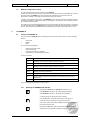
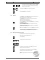
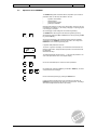
Function of the LED's:
M 1 Indicates if sensor 1 is active. Flashes if sensor 1 is read-out.
M 2 Indicates if sensor 2 is active. Flashes if sensor 2 is read-out.
M 3 Indicates if sensor 3 is active. Flashes if sensor 3 is read-out.
M 4 Indicates if sensor 4 is active. Flashes if sensor 4 is read-out.
ALARM Lights in case of an error.
COOL Displays if the cooling is switched on.
HEAT Displays if the heating is switched on.
GAS Lights constantly if gas flows into the ripening room. Flashes if gas is present in the
ripening room.
VENT Lights during ventilation of the ripening room.
In general a flashing LED means that a function is active.
2.1.1 Switching the PROBA 50 ON and OFF
By pressing the ON/OFF key the PROBA 50 is switched on or off.
If the PROBA 50 is switched off, the control will stop immediately.
If the PROBA 50 is switched on, all settings can be displayed.
To change settings, a 4-digit security has to be entered.
Press the KEY button. The display shows the text 'Code'. By use of
combination of keys on the bottom row a code can be entered.
If the code is correct, the LED above the KEY button will light and settings can
be changed. The lock is open.
By pressing the KEY button again, the LED above the KEY button will
extinguish and it is not possoble to change the settings. The lock is closed.

VDH Products BV Document 951573 - Version 1.3 Blad: 6 of 26
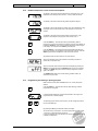
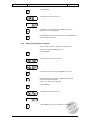
2.1.2 Readout temperature, clock, sensors and setpoints
The display in the top left shows the temperature in the ripening room. This
temperature is the average of the sensors 1, 2 and 3 (if these are active).
The display in the bottom left shows the present temperature setpoint.
The display in the top right shows the program clock, which indicates how long
the program has run in the present day. In this example 15 hours and 24
minutes.
The display in the bottom right shows the length and present day of the
program. In this example a 5 day program, which is now in day 3.
Press the PROG key. The LED above the key starts flashing. When a
program is in progress, the number of that program is shown in the display. By
pressing the PROG key once more, the average temperature is shown again
in the display. The LED above the PROG key will extinguish.
Press the SENS key. The LED above the key starts flashing indicating that
this function is active. The temperature of the first sensor is shown. Press the
SENS key again and the temperature of the next sensor is shown.
All present sensors are shown, also the non active sensors.
After the temperatures there is an indication if the heating can switch on
(HEAT ON) or not (HEAT OFF).
After the measured values of all sensors have been displayed, pressing the
SENS key once again will bring the PROBA 50 back into its normal working
condition. The SENS-LED goes off and the average temperature is shown
again in the display.
The PROBA 50 will switch to the normal working condition if within 30
seconds no key is touched.
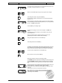
2.1.3 Programming and starting a ripening program
Make sure that the LED above the KEY button is on, so that changes are
allowed.
Press the PROG key. The LED above this key starts flashing to indicate
programming is in progress.
In the temperature display the program number flashes. The length of the
program is shown in the DAY display.
The ripening program number (here number 3) can be changed by means of
the UP and DOWN keys.
By pressing the SET key the selected number is accepted.
The number of days of programs 1 to 5 is fixed (4 days with program number
1 and soon to 8 days with program number 5).
If one of the programs 6 to 10 is selected, the number of days can be selected
in addition to temperature.

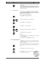
VDH Products BV Document 951573 - Version 1.3 Blad: 7 of 26
The number of days of this program can now be selected and is shown in the
DAY display. The length can vary from 1 to 9 days.
With the UP and DOWN keys the length of the program can be changed.
Acknowledge the number of days with the SET key.
From this point on setting up of programs 6 to 10 is the same as setting up
programs 1 to 5.
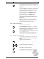
During the first day of the ripening program the fruit can be gassed. With the
UP and DOWN keys the user can select gasification ('G. on') or no gasification
('G.oFF'). The GAS LED also flashes.
Press the SET key if the setting is right.
Ventilation of the ripening rooms can now be adjusted. The VENT LED
flashes.
The ventilation time and the frequency of the ventilation can be set in the
Internal Adjustments.
During the gasification period ventilation is blocked. As soon as the
gasification period is ended, ventilation starts immediately.
Change the adjustment with the UP and DOWN keys.
Acknowledge selection with the SET key.
The setting of the temperatures of the ripening program now follow. For every
day a temperature can be selected.The DAY display indicates which day is
being set, while the temperature display shows the desired value (setpoint).
The value can be changed with the UP and DOWN keys.
When the value is correct, press the SET key.
Repeat the last steps for all days of the ripening program.
The STANDBY temperature (setpoint after finishing the actual ripening) is set
while the STANDBY LED lights. Changing of this value is done in the same
manner as adjustment of other setpoints (UP and DOWN keys and the SET
key).
Finally a delay time can be set before the actual ripening program starts. This
period is called day 0. Therefore the 0 lights in the DAY display.
By pressing the UP and DOWN keys and the SET key a delay time in hours
can be set.
If the delay time is 0 hours, the program will start directly.
When a delay time of more than 0 hours is programmed, the temperature
setpoint for day 0 can be adjusted with the UP and DOWN keys and
acknowledged with the SET key.

VDH Products BV Document 951573 - Version 1.3 Blad: 8 of 26
By pressing the SET key for the last time, the ripening program will start. The
PROG LED lights to indicate that the ripening program is in progress and the
fruit is being ripened.
Please note:
During day 0 the PROBA 50 will, if selected, start with ventilation and regulate
the temperature. If the delay time is finished, the ripening program will step to
day 1 and continue the program.
The program clock will count down to 00.00 hours in day 0. The program
steps to day 1 and the clock will count from 00.00 hours.
While programming programs 1 to 5, the PROBA 50 will use the pre-
programmed ripening programs as default.
While programming programs 6 to 10, the PROBA 50 will use the
temperatures of the last ripening program used.
If ripening programs 6 to 10 are adjusted during programming or during the
ripening process, these changed values are default settings for the next time
the program is used.
Programming can be interupted at any time by pressing the PROG key. The
PROG LED will stop flashing and programming will not have any effect.
If during programming no key has been pressed for more than 30 seconds,
programming will be interrupted and changes are not made.
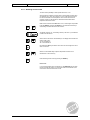
2.1.4 Stopping a ripening program
Make sure the LED above the KEY button is on.
By pressing the STANDBY key, the program is forced into the STANDBY
mode. The STANDBY LED above this key lights.
Because of this the ripening program will regulate for unlimited time on the
STANDBY temperature setpoint. If selected, the ventilation times will be taken
into account. The PROG LED does not light anymore.
By pressing the STANDBY key once more, the STANDBY mode is switched
off and the PROBA 50 stops regulating.
The temperature regulation stops, the ripening room will not be kept on a
constant temperature. Also the STANDBY LED does not light anymore.
2.1.5 Changing the temperature setpoint
To allow the ripener to adapt the ripening program whilst it is running, it is
possible to change the setpoint of the current day. This is only possible when
the PROG or the STANDBY LED are lit, which shows that the PROBA 50 is
regulating.
Make sure the LED above the KEY button is on.
Press the SETPOINT key. The present temperature setpoint starts to flash.
The value can be changed with the UP and DOWN keys.
Press the SET key to acknowlegde the adjustment.
The temperature setpoint of one of the other days can also be changed.
Press the SETPOINT key so that the present temperature setpoint flashes.

VDH Products BV Document 951573 - Version 1.3 Blad: 9 of 26
By simultaneously pressing the DAY-key and the UP- or DOWN-
key, another day can be selected. The setpoint for this day will
appear in the setpoint display.
Using the UP- and DOWN-keys the setpoint can be changed.
Press the SETPOINT-key to exit the setting.
2.1.6 Standby
In the STANDBY mode the PROBA 50 will regulate for unlimited time on a
fixed setpoint temperature in the ripening room.
This STANDBY mode for example can be used if products other than
bananas are stored in the ripening room.
Make sure the LED above the KEY button is on.
Press the STANDBY key to switch to the STANDBY mode. The LED above
the STANDBY key will light.
Now the temperature will be regulated for an unlimited time on the last
programmed STANDBY setpoint.
The setpoint can be adjusted as described in chapter '2.1.5. Changing the
temperature setpoint' (see page 8).
By pressing the STANDBY key once more, the STANDBY mode is switched
off.
The temperature regulation will stop, the ripening room will not be kept at a
constant temperature. Also the STANDBY LED will not illuminated.
2.1.7 Starting and stopping the gassing
It is possible to stop the gasification during a gassing period.
Make sure the LED above the KEY button is on.
Press the GAS key.
The display shows the text 'GAS' and 'StOP'.
If gasification is not to be stopped, press the GAS key. The average
temperature shows in the display again.
Press the SET key to stop the gasification period. The LED GAS will
extinguish to indicate that gasification has stopped.
During the ripening program it is possible to insert (once again) a gassing
period.

VDH Products BV Document 951573 - Version 1.3 Blad: 10 of 26
Press the GAS key.
The display shows the text 'GAS' and 'on'.
If gasification is not to be started, press the GAS key. The average
temperature shows in the display again.
Press the SET key to start the gasification period. The LED GAS will light to
indicate that gasification is active.
2.1.8 Starting and stopping the ventilation
If there is ventilation, this can be stopped in the following manner.
Make sure the LED above the KEY button is on.
Press the VENT key.
The display shows the text 'VENt' and 'StOP'.
If ventilation is not to be stopped, press the VENT key once more.
Press the SET key to stop ventilation. The VENT LED will extinguish
indicating that ventilation has stopped.
If there is no ventilation, this can be started.
Press the VENT key.
The display shows the text 'VENt' and ' on'.
Press the VENT key once more if ventilation is not to be started.

VDH Products BV Document 951573 - Version 1.3 Blad: 11 of 26
Press the SET key to start ventilation. The VENT LED will light to indicate that
ventilation is active.
When the ventilation is actived in this manner, the system will commands a
cycle which is pre-programmed into the Interal Settings, e.g. 20 minutes every
12 hours (if the gas cycle is activated, ventilation will stop and then continues
automatically after gassing).
2.1.9 Stepping a program
During the course of a ripening program, it is possible to change the program
clock or the day in which the PROBA 50 is running. We call this 'Stepping' a
program. With this 'Stepping' the length of a program can be made shorter by
stepping forward or longer by stepping back.
Make sure the LED above the KEY button is on.
Press the TIME key. The program clock flashes.
The time can be changed using the UP and DOWN keys.
Press the TIME key to confirm the new setting.
Press the DAY key. The day number flashes.
The day number can be changed using the UP and DOWN keys.
Press the DAY key to confirm the selected day.
Please note:
It is not possible to step from a program to STANDBY. This is only possible by
pressing the STANDBY key.
Nor is it possible to step from STANDBY back into a program.
2.1.10 Heating on/off switch
The PROBA 50 offers the option to switch off the heating. During temperature
control there will only be cooling. If the temperature is lower than the setpoint,
the heating will not switch on.
Make sure the LED above the KEY button is on, so that changes are allowed.
Press the SENS-key until the text 'HEAT ON' or 'HEAT OFF' appears in the
display.
Press the SET key to change from ON to OFF or reverse.
Press the SENS key once more, so that the average value of the temperature
sensors appears in the display again.

VDH Products BV Document 951573 - Version 1.3 Blad: 12 of 26
2.1.11 Switching sensors on/off
The user has the possibility to switch present sensors on or off.
Sensors which are switched on will be used for the regulation, sensors which
are switched off not. This can be useful e.g. if one of the sensors should not
be used for calculation of the temperature. Also a sensor which does not
measure correctly can be switched off. Illuminated LED's indicate which
temperature sensors are active.
Make sure the LED above the KEY button is on, so that changes are possible.
Press the SENS key and then the PROG key. The LED's above these keys
start flashing to indicate that this function is active.
The display shows 'S1.on'. The flashing number (in this case '1'), indicates the
number of the first sensor.
Select a sensor with the UP and DOWN keys. The display shows whether the
sensor is ON or OFF:
'on' if it is switched on,
'OF' if it is switched off.
By pressing the SET key the status of the sensor can be changed from ON to
OFF or vice versa.
With the UP and DOWN keys all present temperature sensors can be
switched ON or OFF in this way.
Finish switching sensors on/off by pressing the SENS key.
Please note:
If only one temperature sensor is switched on, the PROBA 50 does not allow
the user to switch this sensor off. If this sensor needs to be switched off, the
user needs to switch another sensor on first.

VDH Products BV Document 951573 - Version 1.3 Blad: 13 of 26
2.2 Adjustment of the PROBA50
The PROBA 50 regulates and detects failures, dependant upon a number of
parameters which can be set by the installer or the user:
*regulation characteristics
* alarms/warnings
* default ripening programs
* gassing and ventilation
Normally these settings do not have to be changed daily. This is why they are
more difficult to access than e.g. the starting or stopping of a ripening program
or the changing of a setpoint.
We call changing of these settings we call 'Internal Programming'.
The PROBA 50 can be brought into this Internal Programming mode by
simultaneously pressing the SET and KEY buttons. Start by pressing the SET
key; then the KEY key.
Since most of the settings in the Interal Programming affect the regulation
characterisics of the PROBA 50, all controls are inactive, for as long as the
PROBA 50 is in the Internal Programming mode.
In Appendix B all parameters are shown.
The text 'iP--' appears in the display. The horizontal bar moves between the
third and fourth position. Keep both buttons pressed for two seconds and the
bar disappears.
Release the two keys.
The temperature display shows the text 'P 1'. This is the first parameter. The
value of this parameter is shown in the setpoint display.
Use the UP and DOWN keys to choose the various parameters.
By simultaneously pressing the SET key and the UP or DOWN key, the value
of the parameter can be changed.
End the 'Internal Programming' by pressing the PROG button.
If during the Internal Programming no key is pressed for 60 seconds, the
PROBA 50 stops programming and returns to it's previous state. The settings
which were changed will not be stored in the memory.

VDH Products BV Document 951573 - Version 1.3 Blad: 14 of 26
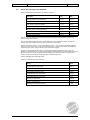
2.3 Regulation characteristics of the PROBA 50
Description Min. Max. Step
Cooling Differential 0.1°C 20.0°C 0.1°C
Cooling Offset -20.0°C +20.0°C 0.1°C
Heating Differential 0.1°C 20.0°C 0.1°C
Heating Offset -20.0°C +20.0°C 0.1°C
Gas Supply Time 0 min 500 min 1 min
Total Gassing Time 0 hrs 99 hrs 1 hrs
Ventilation Time 0 min 240 min 1 min
Ventilation Interval 1 hrs 24 hrs 1 hrs
The two controls (Cooling and Heating) operate in such a way that the corresponding relays switch off at the
setpoint. If the measured value differs more than the differential (hysterisis) from the setpoint, the relay switches on.
This is assuming that for cooling and heating there is no offset.
If there is an offset, the effective setpoint (which is used for regulation) shifts with the offset value relative to the
setpoint.
The following values are default values set at the factory:
Adjustment Value
Cooling Differential 0.2°C
Cooling Offset -0.1°C
Heating Differential 0.2°C
Heating Offset -0.6°C
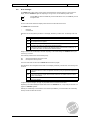
The resulting characteristics of the heating and cooling controls are:
Please note:
When changing differentials and offsets of cooling and heating, the PROBA 50 ensures that no situations arise with
which it is possible that cooling and heating are switched on at the same time. In case the user tries to change the
parameter in this way, the PROBA 50 signals and the faulty adjustment is blocked.

VDH Products BV Document 951573 - Version 1.3 Blad: 15 of 26
2.4 Alarms and warnings of the PROBA 50
Alarms and warnings are adjustable within the following parameters:
Description Min. Max.
Absolute Maximum Temperature Alarm -10.0°C +40.0°C
Absolute Minimum Temperature Alarm -10.0°C +40.0°C
Delay Relative Temperature Warning 0 min 99 min
Relative Maximum Temperature Warning 0.0°C +40.0°C
Relative Minimum Temperature Warning -40.0°C 0.0°C
Maximum Air Temperature -10.0°C +40.0°C
Minimum Air Temperature -10.0°C +40.0°C
All active temperature sensors are continuously checked for exceeding the absolute temperature limits. If that
happens, a Fatal Alarm will follow.
There are also relative temperature limits. These are linked to the current temperature setpoint. If the setpoint
changes, these limits change by the same amount. These alarms can be delayed.
Example: Temperature setpoint = 16.0°C; Relative Maximum Alarm = +4.0°C; The limit of the Relative Maximum
Alarm is at 20.0°C. As soon as one of the sensors goes above 20.0°C, a delay timer is started. If the temperature
remains higher than 20.0°C during the set time, a Non Fatal Alarm is triggered.
If sensor 4, the air temperature alarm sensor, is connected and measures a temperature which is above the
Maximum Air Temperature Alarm, the heating relay is blocked and released again if the air temperature is below the
Maximum Alarm level. If the air temperature is below the Minimum Air Temperature Alarm, the cooling relay is
blocked. It is released if the temperature has risen above the Minimum Alarm level.
Changing these parameters is described earlier.
Standard values which are set at the factory are:
Setting Value
Absolute Maximum Temperature +22.0°C
Absolute Minimum Temperature +10.0°C
Delay Relative Temperature Alarm 30 min
Limit Relative Maximum Temperature +4.0°C
Limit Relative Minimum Temperature -4.0°C
Maximum Air Temperature +20.0°C
Minimum Air Temperature +10.0°C
Differential Air Temperature Limitation 0.5°C

VDH Products BV Document 951573 - Version 1.3 Blad: 16 of 26
2.5 Error messages
The PROBA 50 has a large variety of ways to detect errors and failures. These are shown in an error code in the
display, while the ALARM LED lights and, depending on the type of error, the ALARM relay makes contact.
Pressing KEY can reset the ALARM relay. When several failures occur, use the SET key to scroll
through the errors.
The error code remains visible in the display until the cause of the alarm has been removed.
The PROBA 50 has two fault levels:
*fatal errors
* non fatal errors
Fatal Errors can be recognized by the letter 'E' in the display, followed by a number code. The meaning of the code
is:
E 1 All present temperature sensors are at fault
E 2 No temperature sensor present
E 2x Temperature sensor x is higher than the absolute maximum (x is the sensor number). E.g. 'E
22' means that sensor 2 is higher than the absolute maximum.
E 3x Temperature sensor x is lower than the absolute minimum (x is the sensor number). E.g. 'E
31' means that sensor 1 is lower than the absolute minimum.
During a Fatal Error the ALARM relay is activated. Depending on the Internal Settings the PROBA 50 will stop the
control or try to continue.
At the following Fatal Errors the control will always stop:
E 1 All present temperature sensors are at fault.
E 2 No temperature sensors present.
As soon as these faults are removed, the PROBA 50 will continue the program.
Non Fatal Errors can be recognized from the letter 'F' in the display, followed by a number code. The meaning of the
number is:
F x Temperature sensor x at fault. The regulation continues by using the operational temperature
sensors.
F 2x Temperature sensor x is higher than the relative maximum. The relative maximum is linked
to the current setpoint.
F 3x Temperature sensor x is lower than the relative minimum. The relative minimum is linked to
the current setpoint.
In Appendix A (Error messages, see page 18) all possible fatal and non fatal errors are listed.
Depending on the Internal Settings the alarms will be active if the PROBA 50 is on, or only during the execution of a
program or STANDBY regulation.
Selecting the ALARM relay to be resetable or not is achieved by the SET key. In the last situation the ALARM relay
will drop out when the faults are removed.

VDH Products BV Document 951573 - Version 1.3 Blad: 17 of 26
3Datalogger
The PROBA 50 stores every hour measured temperatures, setpoint and the status of the relay. The data of the last 28 days is
stored in the memory.
During power failure of the PROBA50 logging will stop. The unit records that there has been a power failure.
By connecting the COM1 port of a computer to the RS 232 port of the PROBA 50, pre-recorded data can be downloaded to
the computer. The required software is available on request from VDH Products.
The data is stored in a DOS file, which can be edited using a normal editor.
The file will display the following data:
TIME - Date/time of the measurement
MODE - Status of the PROBA50
* Power off - switched of via ON/OFF
* Off - no program or standby
* Run - in program mode
* Stdby - in standby mode
SETP - Setpoint
AVERAGE - Control temperature
SENS 1 - Temperature sensor 1
SENS 2 - Temperature sensor 2
SENS 3 - Temperature sensor 3
SENS 4 - Temperature sensor 4
PF - Power failure during last hour
IP -Internal Programming accessed during last hour
COOL - Cooling relay activated during last hour
HEAT - Heating relay activated during last hour
VENT - Ventilation relay activated during last hour
GAS -Gassing relay activated during last hour
H.DIS - Heating function switched off
The date/time is calculated from the last measurement. This measurement obtains the actual date/time from the PC clock. The
date/time before a power failure could be wrong !

VDH Products BV Document 951573 - Version 1.3 Blad: 18 of 26
Appendix A (Error messages)
Summary of error messages PROBA 50
type 'E' = Fatal Error.
type 'F' = Non Fatal Error.
Table of Fatal Errors
E 1 All present temperature sensors are at fault
E 2 No temperature sensor present
E 21 Temperature of sensor 1 exceeds absolute maximum
E 22 Temperature of sensor 2 exceeds absolute maximum
E 23 Temperature of sensor 3 exceeds absolute maximum
E 24 Temperature of sensor 4 exceeds absolute maximum
E 31 Temperature of sensor 1 below absolute minimum
E 32 Temperature of sensor 2 below absolute minimum
E 33 Temperature of sensor 3 below absolute minimum
E 34 Temperature of sensor 4 below absolute minimum
Table of Non-Fatal Errors
F 1 Temperature sensor 1 is at fault
F 2 Temperature sensor 2 is at fault
F 3 Temperature sensor 3 is at fault
F 4 Temperature sensor 4 is at fault
F 21 Temperature of sensor 1 exceeds relative maximum
F 22 Temperature of sensor 2 exceeds relative maximum
F 23 Temperature of sensor 3 exceeds relative maximum
F 31 Temperature of sensor 1 below relative minimum
F 32 Temperature of sensor 2 below relative minimum
F 33 Temperature of sensor 3 below relative minimum

VDH Products BV Document 951573 - Version 1.3 Blad: 19 of 26
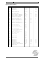
Appendix B (Internal Parameters)
Number Description Range Unit Default
001
002
003
004
010
011
012
013
014
015
016
017
018
019
020
021
022
023
025
026
027
028
030
031
032
033
034
041
042
043
044
051
052
053
054
055
056
060
061
062
Differential cooling
Offset cooling
Differential heating
Offset heating
Absolute maximum alarm
Absolute minimum alarm
Relative maximum alarm
Relative minimum alarm
Delay relative alarm
Absolute maximum air temperature
Absolute minimum air temperature
Relative maximum air temperature
Relative minimum air temperature
Differential air temperature
Gas supply time program 1 to 5
Gassing period program 1 to 5
Ventilation time program 1 to 5
Ventilation interval program 1 to 5
Gas supply time program 6 to 10
Gassing period program 6 to 10
Ventilation time program 6 to 10
Ventilation interval program 6 to 10
Alarm relay resetable
Stop control during alarm
Absolute alarm when no control
Day 0 sensor selection
0 = control on sensor 1, 2 & 3
1 = in day 0 control on sensor 3
else on sensor 1 & 2
Setpoint change valid till the
next setpoint change
Sensor 1 present
Sensor 2 present
Sensor 3 present
Sensor 4 present
Offset sensor 1
Offset sensor 2
Offset sensor 3
Offset sensor 4
Proportional band cooling
I-time cooling (999 is P-function)
Software version
Serial number
Production date
0..20.0
-20..20.0
0..20.0
-20..20.0
-10..40.0
-10..40.0
0..10.0
-10..0.0
0..99
-10..40.0
-10..40.0
0..10.0
-10..0.0
0.1..10
0..500
0..99
0..240
0..48
0..500
0..99
0..240
0..24
0 = no
1 = yes
0 = no
1 = yes
0 = no
1 = yes
0..1
0 = no
1 = yes
0 = no
1 = yes
0 = no
1 = yes
0 = no
1 = yes
0 = no
1 = yes
-10..+10
-10..+10
-10..+10
-10..+10
0.1..+10
0..999
-
-
-
°C
°C
°C
°C
°C
°C
°C
°C
min
°C
°C
°C
°C
°C
min
hrs
min
hrs
min
hrs
min
hrs
-
-
-
-
-
-
-
-
-
0.1°C
0.1°C
0.1°C
0.1°C
°C
min
-
-
year/week
0.2
-0.1
0.2
-0.6
25.0
10.0
5.0
-5.0
30
20.0
10.0
3.0
-3.0
0.5
30
24
30
12
30
24
30
12
0
0
0
0
0
1
1
1
1
0.0
0.0
0.0
0.0
1.0
15
-
-
-

VDH Products BV Document 951573 - Version 1.3 Blad: 20 of 26
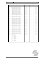
Number Description Range Unit Default
110
111
112
113
114
114
120
121
122
123
124
125
126
130
131
132
133
134
135
136
137
140
141
142
143
144
145
146
147
148
150
151
152
153
154
155
156
157
158
159
999
Temperature day 0 program 1
Temperature day 1 program 1
Temperature day 2 program 1
Temperature day 3 program 1
Temperature day 4 program 1
Temperature standby program 1
Temperature day 0 program 2
Temperature day 1 program 2
Temperature day 2 program 2
Temperature day 3 program 2
Temperature day 4 program 2
Temperature day 5 program 2
Temperature standby program 2
Temperature day 0 program 3
Temperature day 1 program 3
Temperature day 2 program 3
Temperature day 3 program 3
Temperature day 4 program 3
Temperature day 5 program 3
Temperature day 6 program 3
Temperature standby program 3
Temperature day 0 program 4
Temperature day 1 program 4
Temperature day 2 program 4
Temperature day 3 program 4
Temperature day 4 program 4
Temperature day 5 program 4
Temperature day 6 program 4
Temperature day 7 program 4
Temperature standby program 4
Temperature day 0 program 5
Temperature day 1 program 5
Temperature day 2 program 5
Temperature day 3 program 5
Temperature day 4 program 5
Temperature day 5 program 5
Temperature day 6 program 5
Temperature day 7 program 5
Temperature day 8 program 5
Temperature standby program 5
Password
0 = PRG key
1 = STBY key
2 = GAS key
3 = VENT key
4 = SENS key
5 = SET key
6 = UP key
7 = DOWN key
8 = KEY key
7 = ON/OFF key
-10..40.0
-10..40.0
-10..40.0
-10..40.0
-10..40.0
-10..40.0
-10..40.0
-10..40.0
-10..40.0
-10..40.0
-10..40.0
-10..40.0
-10..40.0
-10..40.0
-10..40.0
-10..40.0
-10..40.0
-10..40.0
-10..40.0
-10..40.0
-10..40.0
-10..40.0
-10..40.0
-10..40.0
-10..40.0
-10..40.0
-10..40.0
-10..40.0
-10..40.0
-10..40.0
-10..40.0
-10..40.0
-10..40.0
-10..40.0
-10..40.0
-10..40.0
-10..40.0
-10..40.0
-10..40.0
-10..40.0
1111-9999
°C
°C
°C
°C
°C
°C
°C
°C
°C
°C
°C
°C
°C
°C
°C
°C
°C
°C
°C
°C
°C
°C
°C
°C
°C
°C
°C
°C
°C
°C
°C
°C
°C
°C
°C
°C
°C
°C
°C
°C
-
14.5
18.0
18.0
16.5
15.5
15.0
14.5
16.5
16.5
16.5
16.5
15.5
15.0
14.5
16.5
16.5
15.5
15.5
15.5
14.5
14.0
14.5
15.5
15.5
15.5
15.5
15.5
14.5
14.5
14.0
14.5
14.5
14.5
14.5
14.5
14.5
14.5
14.5
14.5
14.0
1234
Page is loading ...
Page is loading ...
Page is loading ...
Page is loading ...
Page is loading ...
Page is loading ...
-
 1
1
-
 2
2
-
 3
3
-
 4
4
-
 5
5
-
 6
6
-
 7
7
-
 8
8
-
 9
9
-
 10
10
-
 11
11
-
 12
12
-
 13
13
-
 14
14
-
 15
15
-
 16
16
-
 17
17
-
 18
18
-
 19
19
-
 20
20
-
 21
21
-
 22
22
-
 23
23
-
 24
24
-
 25
25
-
 26
26


Ask a question and I''ll find the answer in the document
Finding information in a document is now easier with AI
Related papers
Other documents
-
 JKN WTS-3 Quick start guide
-
 POLA HP53 User manual
-
Livoo DOM464 User manual
-
HEIDENHAIN ND 1200 Owner's manual
-
-
Omega OM-EL-CC Owner's manual
-
Summit SHELFKIT532 User guide
-
Sub-Zero 736TFI User manual
-
Sub-Zero 736TI Troubleshooting guide
-
 AutoFlo ESU-20 Owner's manual


