Page is loading ...

Your Power Solutions Partner
AMPS HP2 Power System
Installation & Operation Manual
Part #0260080-J0
Effective 01/2017
member of The Group
™


1
0260080-J0 Rev B
For technical support, contact Alpha Technologies:
Canada and USA: 1-888-462-7487
International: +1-604-436-5547
Copyright
Copyright © 2017 Alpha Technologies Ltd. All rights reserved. Alpha is a registered trademark of Alpha Tech-
nologies.
No part of this documentation shall be reproduced, stored in a retrieval system, translated, transcribed, or
transmitted in any form or by any means manual, electric, electronic, electromechanical, chemical, optical, or
otherwise without prior explicit written permission from Alpha Technologies.
This documentation, the software it describes, and the information and know-how they contain constitute the
proprietary, confidential and valuable trade secret information of Alpha Technologies, and may not be used
for any unauthorized purpose, or disclosed to others without the prior written permission of Alpha Technolo-
gies.
The material contained in this document is for information only and is subject to change without notice.
While reasonable efforts have been made in the preparation of this document to assure its accuracy, Alpha
Technologies assumes no liability resulting from errors or omissions in this document, or from the use of the
information contained herein. Alpha Technologies reserves the right to make changes in the product design
without reservation and without notification to its users.
AMPS HP2 Power Systems
Alpha shall not be held liable for any damage or injury involving its enclosures,
power supplies, generators, batteries, or other hardware if used or operated in any
manner or subject to any condition not consistent with its intended purpose, or is
installed or operated in an unapproved manner, or improperly maintained.
Photographs contained in this manual are for illustrative purposes only. These pho-
tographs may not match your installation.
NOTE:
Operator is cautioned to review the drawings and illustrations contained in this
manual before proceeding. If there are questions regarding the safe operation of this
powering system, contact Alpha Technologies or your nearest Alpha representative.
NOTE:
NOTE:

0260080-J0 Rev B
2
Table of Contents
1. Safety ������������������������������������������������������������������������������������������������������������������������������������6
1�1 Safety Symbols ������������������������������������������������������������������������������������������������������������������������������������6
1�2 General Warning and Cautions ������������������������������������������������������������������������������������������������������������6
1�3 General Safety �������������������������������������������������������������������������������������������������������������������������������������7
1�4 External Battery Safety ������������������������������������������������������������������������������������������������������������������������8
1�5 Utility Power Connection ����������������������������������������������������������������������������������������������������������������������8
1�6 Equipment Grounding ��������������������������������������������������������������������������������������������������������������������������9
2� Product Description�������������������������������������������������������������������������������������������������������������10
2.1 Power System Conguration Terminology �����������������������������������������������������������������������������������������10
2�2 Theory of Operation ��������������������������������������������������������������������������������������������������������������������������� 11
3. Module Specications ���������������������������������������������������������������������������������������������������������15
3.1 Specications for 48-120 Inverter Module �����������������������������������������������������������������������������������������15
3.2 Specications for 48-2.4kW Rectier Module ������������������������������������������������������������������������������������16
4� AMPS HP2: Box Bay Systems ��������������������������������������������������������������������������������������������17
4.1 Specications AMPS HP2: Box Bay ��������������������������������������������������������������������������������������������������18
4.2 System Pre-Installation ����������������������������������������������������������������������������������������������������������������������20
4�3 System Installation �����������������������������������������������������������������������������������������������������������������������������25
4�4 Installation: AMPS HP2: Box Bay ������������������������������������������������������������������������������������������������������26
4.5 Input/Output Cabling Overview ���������������������������������������������������������������������������������������������������������� 27
4�6 AC Connections ���������������������������������������������������������������������������������������������������������������������������������29
4�7 DC Connections ���������������������������������������������������������������������������������������������������������������������������������32
5. AMPS HP2: Rack Mount Systems ��������������������������������������������������������������������������������������40
5.1 Specications AMPS HP2: Rack Mount ���������������������������������������������������������������������������������������������41
5.2 System Pre-Installation ����������������������������������������������������������������������������������������������������������������������43
5�3 System Installation �����������������������������������������������������������������������������������������������������������������������������45
5.4 Installation: AMPS HP2: Rack Mount �������������������������������������������������������������������������������������������������46
5�5 AC Connections ���������������������������������������������������������������������������������������������������������������������������������48
5�6 DC Connections ���������������������������������������������������������������������������������������������������������������������������������49
6� System Components�����������������������������������������������������������������������������������������������������������50
6�1 Cordex HP Controller ������������������������������������������������������������������������������������������������������������������������� 50

3
0260080-J0 Rev B
6.2 L-ADIO �����������������������������������������������������������������������������������������������������������������������������������������������53
6.3 T2S Inverter Control Card ������������������������������������������������������������������������������������������������������������������ 55
6.4 Inverter Module Indicators �����������������������������������������������������������������������������������������������������������������56
6.5 Rectier Features �������������������������������������������������������������������������������������������������������������������������������57
7� Commissioning the System ������������������������������������������������������������������������������������������������60
7.1 Tools Required �����������������������������������������������������������������������������������������������������������������������������������60
7.2 Commissioning the Inverter System ��������������������������������������������������������������������������������������������������62
8� System Maintenance ����������������������������������������������������������������������������������������������������������65
8.1 Preventative Maintenance �����������������������������������������������������������������������������������������������������������������65
8.2 Inverter and T2S Maintenance �����������������������������������������������������������������������������������������������������������67
8.3 Replacing an AIM2500 Inverter Module ���������������������������������������������������������������������������������������������70
8�4 Synchronizing the Maintenance Bypass �������������������������������������������������������������������������������������������� 72
8.5 Fuse Replacement (Box Bay) ������������������������������������������������������������������������������������������������������������ 73
8.6 TVSS Replacement (Box Bay) �����������������������������������������������������������������������������������������������������������74
8.7 Fuse Replacement (Rack Mount) ������������������������������������������������������������������������������������������������������75
8.8 TVSS Replacement (Rack Mount) ����������������������������������������������������������������������������������������������������� 76
8.9 Replacing the T2S Inverter Control Card ������������������������������������������������������������������������������������������� 77
9� Troubleshooting ������������������������������������������������������������������������������������������������������������������78
9.1 Incorrect System Conguration ����������������������������������������������������������������������������������������������������������78
9.2 Wrong Inverter AC Input Group ���������������������������������������������������������������������������������������������������������78
9.3 Wrong Inverter DC Input Group ���������������������������������������������������������������������������������������������������������78
9�4 T2S Expert Operations ����������������������������������������������������������������������������������������������������������������������78
9�5 Troubleshooting and Clearing System Error Alarm ����������������������������������������������������������������������������78
10� Warranty ���������������������������������������������������������������������������������������������������������������������������80
11. Certication �����������������������������������������������������������������������������������������������������������������������81

0260080-J0 Rev B
4
List of Figures
Figure 1 — Split Phase from a Single phase supply ��������������������������������������������������������������������������������10
Figure 2 — 2-Pole from a 3-phase supply ������������������������������������������������������������������������������������������������ 11
Figure 3 — Example wiring for AMPS inverter system w/ independent AC input feed for MBS ���������������12
Figure 4 — System Schematic with Generator and MBS ������������������������������������������������������������������������� 13
Figure 5 — AMPS HP2 Box Bay System ��������������������������������������������������������������������������������������������������14
Figure 6 — AMPS HP2 Rack Mount System �������������������������������������������������������������������������������������������� 14
Figure 7 — AMPS HP2, Large ������������������������������������������������������������������������������������������������������������������17
Figure 8 — Installation layout and clearances ������������������������������������������������������������������������������������������ 21
Figure 9 — Transporting the cabinet ���������������������������������������������������������������������������������������������������������22
Figure 10 — Mounting hole pattern ����������������������������������������������������������������������������������������������������������24
Figure 11 — Battery and power connections ��������������������������������������������������������������������������������������������26
Figure 12 — Top view showing AC and DC connection partitions ������������������������������������������������������������ 27
Figure 13 — Top view showing AC and DC connection ���������������������������������������������������������������������������� 28
Figure 14 — AC Connections (a) �������������������������������������������������������������������������������������������������������������� 29
Figure 15 — AC Connections (b) �������������������������������������������������������������������������������������������������������������� 30
Figure 16 — AC Connections Bypass terminal Block (c) ��������������������������������������������������������������������������31
Figure 17 — Top Feed System, Single Battery Feed ��������������������������������������������������������������������������������33
Figure 18 — Top Feed System, Dual Independent Battery Feeds �����������������������������������������������������������34
Figure 19 — Top Feed System, Four Independent Battery Feeds (no tie bars required) ������������������������� 35
Figure 20 — Bottom Feed System, Single Battery Feed �������������������������������������������������������������������������� 36
Figure 21 — Bottom Feed System, Dual Independent Battery Feeds ������������������������������������������������������37
Figure 22 — Bottom Feed System, Four Independent Battery Feeds (no tie bars required) �������������������38
Figure 23 — Single Battery Feed ��������������������������������������������������������������������������������������������������������������39
Figure 24 — Dual Independent Battery Feeds �����������������������������������������������������������������������������������������39
Figure 25 — Four Independent Battery Feeds (use with no tie bars) ������������������������������������������������������� 39
Figure 26 — AMPS HP2 rack mount, back view ���������������������������������������������������������������������������������������40
Figure 27 — AMPS HP2 rack mount, front view ��������������������������������������������������������������������������������������� 40
Figure 28 — Installation layout and clearances ���������������������������������������������������������������������������������������� 44
Figure 29 — Battery and power connections ��������������������������������������������������������������������������������������������46
Figure 30 — Top view showing AC and DC connection ���������������������������������������������������������������������������� 47
Figure 31 — AC and DC Connections ������������������������������������������������������������������������������������������������������48

5
0260080-J0 Rev B
Figure 32 — Bypass Aux Contacts
AMPS HP2 3-30 ����������������������������������������������������������������������������������������������������������������������������49
Figure 34 — DC Connections, DC1 and DC2 �������������������������������������������������������������������������������������������49
Figure 33 — Bypass Aux Contacts
AMPS HP2 1-10 and 2-20 �������������������������������������������������������������������������������������������������������������49
Figure 35 — Cordex CXC HP Controller (left side view) ��������������������������������������������������������������������������50
Figure 36 — LCD Color Touchscreen Display ������������������������������������������������������������������������������������������51
Figure 37 — Inverter System Menus ��������������������������������������������������������������������������������������������������������52
Figure 38 — L-ADIO I/O Peripheral ����������������������������������������������������������������������������������������������������������53
Figure 39 — T2S front panel ���������������������������������������������������������������������������������������������������������������������55
Figure 40 — Fig. 4.1 Inverter module status, power LEDs ���������������������������������������������������������������������� 56
Figure 41 — Output power indicator LEDs �����������������������������������������������������������������������������������������������56
Figure 42 — Rectier front panel LEDs ����������������������������������������������������������������������������������������������������57
Figure 43 — Locking handle disengaged/engaged ����������������������������������������������������������������������������������59
Figure 44 — Inverter module showing AC input LED �������������������������������������������������������������������������������61
Figure 45 — Commission Inverter System Wizard ����������������������������������������������������������������������������������� 62
Figure 46 — Add/Remove Inverters ���������������������������������������������������������������������������������������������������������67
Figure 47 — Unlocking and locking an inverter module for removal or insertion ��������������������������������������71
Figure 48 — Inserting and removing an inverter module ��������������������������������������������������������������������������71
Figure 49 — MBS fuse locations ��������������������������������������������������������������������������������������������������������������73
Figure 50 — TVSS protection modules ����������������������������������������������������������������������������������������������������74
Figure 51 — T2S LED sequence during initialization �������������������������������������������������������������������������������77

0260080-J0 Rev B
6
1. Safety
SAVE THESE INSTRUCTIONS: This manual contains important safety instructions that
must be followed during the installation, servicing, and maintenance of the product. Keep it in a safe place. Re-
view the drawings and illustrations contained in this manual before proceeding. If there are any questions regard-
ing the safe installation or operation of this product, contact Alpha Technologies or the nearest Alpha representa-
tive.
1.1 Safety Symbols
To reduce the risk of injury or death, and to ensure the continued safe operation of this product, the following
symbols have been placed throughout this manual. Where these symbols appear, use extra care and attention.
The use of ATTENTION indicates specic regulatory/code requirements that may affect
the placement of equipment and /or installation procedures.
WARNING!
WARNING presents safety information to PREVENT INJURY OR DEATH to personnel.
Warnings are indicated by a shock hazard icon, the word WARNING, and a rule beneath
which the information appears.
WARNING!
You must read and understand the following warnings before installing the enclosure
and its component. Failure to do so could result in personal injury or death.
CAUTION!
CAUTION indicates safety information intended to PREVENT DAMAGE to material or
equipment. Cautions are designated with a yellow warning triangle, the word CAUTION,
and a rule beneath which the information appears.
NOTE:
A NOTE provides additional information to help complete a specic task or procedure.
Notes are designated with a checkmark, the word NOTE, and a rule beneath which the
information appears
HOT!
The use of the BURN HAZARD symbol (1508005) on the product indicated a potential
harzard to the technical or user. The AMPS HP2 rear panel surface may exceed 70°C.
1.2 General Warning and Cautions
x Read and follow all instructions included in this manual.
x Only trained personnel are qualified to install or replace this equipment and its components.
x Use proper lifting techniques whenever handling equipment, parts, or batteries.

7
0260080-J0 Rev B
1.3 General Safety
• Only qualified personnel shall install, operate, and service the power system and components.
• Installation instructions provided with each unit.
• Observe all applicable national and local electrical and building codes during installation.
• Maintain the security of all SELV circuits in the system when connecting to other equipment like signaling/
alarm circuits, emergency power off (EPO) circuits, relay contacts, Ethernet or CANbus. The other equip-
ment must be the same circuit type.
• Bolt the AMPS HP2 system securely to the floor.
• Always assume electrical connections and/or conductors are live.
• Turn off all circuit breakers and double-check potentially charged components with a voltmeter before per-
forming installation or maintenance.
• Before installation, verify that the input voltage and current requirements of the load are within the specifica-
tions of the power system. Refer to the product nameplate label.
• Keep tools away from walk areas to prevent personnel from tripping over the tools.
• Wear safety glasses when working under any conditions that may be hazardous to your eyes.
• Do not work on the power system, or connect or disconnect cables, during atmospheric lightning activity.
• Do not let water enter the enclosure as this can cause electrical shorts, shocks, or electrocutions.
• Do not remove the covers of electrical components as this can cause electrical shorts, shocks or electrocu-
tions. There are no user serviceable parts inside.
• The power system is certified for use in restricted access locations only.
• All operators must be trained to perform the emergency shutdown procedure.
• The power system must be connected only to a dedicated branch circuit.
• Equip the utility service panel with a circuit breaker of appropriate rating.
• Do not exceed the output rating of the system when connecting the load.
• External metal surface temperatures on the rear of the AMPS HP2 system can exceed 70°C, do not touch.
Use caution when working around the equipment while it is in operation.
• Always use proper lifting techniques when handling units, modules, or batteries.
• The power system contains more than one live circuit. Voltage may still be present at the output even when
the input voltage is disconnected.
• Minimize the risk of sparks and wear on the connectors. Always switch off the inverter’s battery circuit
breaker before connecting or disconnecting the batteries.
• In the event of a short-circuit, batteries present a risk of electrical shock and burns from high currents. Ob-
serve proper safety precautions.
• Always wear protective clothing, such as insulated gloves, and safety glasses or a face shield when working
with batteries.
• Carry a supply of water, such as a water jug, to wash eyes or skin in case of exposure to battery electrolyte.
• Do not allow live battery wires to contact the enclosure chassis. Shorting battery wires can result in a fire or
possible explosion.
• Replace batteries with those of an identical type and rating. Never install old or untested batteries.
• Only use insulated tools when handling batteries or working inside the enclosure.

0260080-J0 Rev B
8
• Remove all rings, watches and other jewelry before servicing batteries.
• Recycle used batteries. Spent or damaged batteries are environmentally unsafe. Refer to local codes for the
proper disposal of batteries.
• A disconnect switch shall be provided by others for the AC input and AC output circuits.
• Risk of Electric Shock and Fire Hazard: replace fuse with the same type and rating.
1.4 External Battery Safety
• The power system requires an over-current protection device for the external batteries. Follow the local elec-
trical codes.
• Ensure that the external battery connection is equipped with a disconnect.
• If the batteries are stored for extended periods before the installation, charge the batteries at least once
every three months to ensure optimum performance and maximum battery service life.
• Refer to the battery manufacturer’s recommendation to select the correct float and equalize charge voltage
settings. Failure to do so can damage the batteries. Verify that the battery charger’s float and equalize set-
tings are correct.
• The batteries are temperature sensitive. During extremely cold conditions, a battery’s charge acceptance
is reduced and requires a higher charge voltage. During extremely hot conditions, a battery’s charge ac-
ceptance is increased and requires a lower charge voltage. To allow for changes in temperature, the battery
charger must be equipped with a temperature compensating system. For UPS configurations with rectifier,
refer to the rectifier manual for information about temperature compensation.
• If the batteries appear to be overcharged or undercharged, first check for defective batteries and then verify
that the charger voltage settings are correct.
• To ensure optimal performance, inspect the batteries according to the battery manufacturers recommenda-
tions. Check for signs of cracking, leaking, or unusual swelling. Some swelling is normal.
• Check the battery terminals and connecting wires. Periodically clean the battery terminal connectors and re-
tighten them to the battery manufacturer's torque specifications. Coat the terminals with an approved battery
terminal coating such as NCP-2 or No-Ox.
• Verify that the polarity of the cables are correct before connecting the batteries to the power module. The
polarity is clearly marked on the batteries. The battery breaker will trip and the rectifiers may be damaged if
the cables are connected with the wrong polarity.
• Batteries are not provided and external battery cabinets are not part of this certification.
1.5 Utility Power Connection
Connecting to the utility must be performed by qualified service personnel only and must comply with local elec-
trical codes. The utility power connection must be approved by the local utility before the installation.
CAUTION!
Risk of electric shock, do not remove panels or covers. There are no user serviceable
parts inside. Refer to qualied personnel.
WARNING!
The battery polarity must be correct or damage will result.

9
0260080-J0 Rev B
1.6 Equipment Grounding
To provide a ready, reliable source of backup power, the power system must be connected to an effective
grounding and earthing system. The grounding system must be designed to protect both personnel and equip-
ment.
1.6.1 Safety Ground
The safety ground is a two-part system – the utility service ground and the power system ground.
Utility Service Ground
As a minimum requirement for the protection of equipment, the local utility service must provide a low-impedance
path for fault current return to Earth. This must meet or exceed the requirements of the US National Electrical
Code or the Canadian Electrical Code.
Power System Ground
The power system ground consists of a low-impedance connection between the enclosure and an Earth Ground,
which must be located at least six feet away from the utility earth connection.
1.6.2 Lightning Strike Ground
Lightning strikes, grid switching, or other power surges on the power line and/or communications cable can
cause high-energy transients that can damage the power or communications systems. Without a low-impedance
path to the ground, the current will travel through wires of varying impedance, which can produce damaging high
voltages. The best method to protect the system from damage is to divert unwanted high-energy transients along
a low-impedance path to the ground. See 8.6 for information on the surge suppression modules installed in the
AMPS HP2.
• AMPS-3-75 and AMPS-2-40 UPS are rated for use on a circuit capable of delivering no more than 10 KA rms
symmetrical amperes, 120V maximum.
• AMPS-3-30, AMPS2-20 and AMPS-1-10 UPS are rated for use on a circuit capable of delivering nor more
than 5 KA rms symmetrical amperes, 120V maximum.
WARNING!
Risk of electric shock. The UPS equipment powered by this service panel requires
the neutral to be bonded to ground. Disconnect the UPS DC batteries before servic-
ing the panel.
WARNING!
High leakage current. Earth connections essential before connecting power supply.
Low impedance grounding is mandatory for personnel safety, critical for the proper
operation of the system, and must be in place and connected to the system before
the supply cables are connected.
WARNING!
Multiple power inputs: disconnect all inputs before servicing to avoid electric shock.

0260080-J0 Rev B
10
2. Product Description
The Alpha Modular Power System (AMPS HP2) is a unique, high performance AC and hybrid AC/DC power
system that is ideally suited to provide highly reliable back-up power to cable headend, telecom or server room
facilities.
The AMPS HP2 features hot swappable 2.5 kVA/2.0 kW inverter modules and optional 2.4 kW rectifier modules
that are the building blocks of a highly reliable power system. A smart, unified controller with an integrated Ether-
net/SNMP monitors and manages both inverter and rectifier modules through a web based interface and a local
LCD touch screen. The AMPS HP2 is designed to be installed in a climate-controlled environment where ambient
temperatures are between -20°C to 40°C.
2.1 Power System Configuration Terminology
This section lists the power configurations available with the system and defines the terminology used throughout
this manual.
120Vac Single Phase
A single phase system is 120Vac from L1 to N (neutral).
120/240Vac Split Phase
The term 120/240Vac SPLIT PHASE is used throughout this manual to identify the “3-wire/ 2 legs from a single
phase supply” configuration shown in Figure 1.
L2
N
L1
240V
120V120V
Figure 1 — Split Phase from a Single phase supply
120/208Vac 2-Pole
The term 120/208 2-POLE is used throughout this manual to identify the “2-pole from a 3-phase supply” configu-
ration such as L2 to L3 shown in Figure 2

11
0260080-J0 Rev B
L2
N
L3
L1
208V
208V
208V
120V
120V
120V
Figure 2 — 2-Pole from a 3-phase supply
120/208Vac 3-Phase
Each phase conductor is 120 degrees out of phase with the other, as shown in Figure 2. All three phases (3-pole)
plus the neutral are in use.
When AC Mains is unavailable, DC battery power is converted to AC with zero transfer time. An intelligent high
voltage DC bus decides when to draw power, and how much power to draw, from AC or DC source. During AC
input brownout condition, output power is supplemented by battery power.
AC to DC input transfer can also be automatically triggered via the system controller to enable advanced opera-
tion such as utility peak shaving.
In case of a fault, advanced DSP controls allow the AMPS module to isolate itself, while the rest of the system
continues to power the load (with reduced output).
DSP
Telecom Grade
AC Output
DC In
AC
Mains
communication
CAN bus external
Dual redundant
synchronization
communication and
between modules
2.2 Theory of Operation
Each AMPS module includes a reliable 48Vdc to 120Vac inverter as well as an AC-to-DC converter. When AC
Mains is available, AC power is converted to a high voltage DC bus, which is then converted back to AC. In this
high performance (HP) mode, AMPS delivers fully conditioned, line-regulated telecom-grade AC power with 94%
system efficiency.

0260080-J0 Rev B
12
AMPS modules also have a ‘Boost’ over-current feature with 10 times the rated current capacity for 20ms, allow-
ing it to trip breakers downstream, thus protecting the load.
2.2.1 AC or DC input priority
The user can choose either AC or DC input priority. If AC priority is chosen, the AMPS HP2 acts more like an
on-line, double conversion UPS. If AC commercial power is available, this power is filtered twice and passed
to the AC output. If the AC commercial power fails, the DC converter simply takes over and supplies the
power from the batteries.
If DC priority is chosen, the AMPS HP acts more like an Inverter with AC bypass function. Normally, power
is drawn from the batteries. If DC power fails, the AC-DC converter takes over, still providing regulated and
filtered power to the load.
2.2.2 AMPS HP External Maintenance Bypass Switch
This diagrams show the logical internal connections. They are not a detailed representation of the actual internal
system wiring.
Figure 3 — Example wiring for AMPS inverter system w/ independent AC input feed for MBS
Generator
Main
Distribution
Panel
Utility
Dedicated
UPS
Distribution
Panel
Critical
Systems
Power
External
Maintenance
Bypass
Switch
UPS
BYPASS
Automatic
Transfer
Switch
Rectifier
(optional)
Inverters
Make before break
manual bypass
switch
AMPSHP2
Inverter AC Input
AC Output
Battery
Connection
400A for AMPS80-3-75
AMPS80-2-40
200A for AMPS80-3-30
AMPS80-2-20
AMPS HP2 Installation Diagram for
separate AC input feeds for the
Inverter/MBS and Rectifiers
Rectifier AC Input
DSP
400 Vdc
Boost
Telecom Grade
AC Output
DC In
AC
Mains
communication
CAN bus external
Dual redundant
synchronization
communication and
between modules

13
0260080-J0 Rev B
HP2
2.2.3 Wiring for Generator and/or External MBS
Refer to Figure 4 for schematic of a system with a generator and/or external MBS.
Figure 4 — System Schematic with Generator and MBS

0260080-J0 Rev B
14
2.2.4 AMPS HP2 Models
The versatile AMPS HP2 can be configured for use as an Inverter or a UPS in either single, split, or three-phase
arrangements. 19-inch and 23-inch rack-mount versions are available in 10-30kVA inverter configurations. The
seven-foot Box Bay, 40kVA & 75kVA are available as an Inverter or a UPS. All AMPS HP2 products use the same
core modular inverter modules and are controlled by Alpha’s CXC HP controller. See section 4 for details on the
Box Bay systems, and section 5 for details on the Rack Mount systems.
Box Bay System configurations are:
• 2-40: 120/240Vac Split Phase or 120/208VAC 2 Phase; 40kVA Capacity
• 3-75: Three Phase 120/208VAC; 75kVA Capacity 68kVA/54kW N+1 rating
Both Box Bay systems are available as a UPS configuration using Cordex 2.4kW high efficiency rectifiers. System
are available with Top Feed AC and DC or Top Feed AC and Bottom Feed DC from the factory.
Rack Mount System Configurations are:
• 1-10: Single Phase 120V; 10kVA Capacity
• 2-20: 120/240V Split Phase or 120/208V 2-Pole; 20kVA Capacity
• 3-30: Three Phase 208V; 30kVA Capacity
Figure 5 — AMPS HP2 Box Bay System
Figure 6 — AMPS HP2 Rack Mount System

15
0260080-J0 Rev B
3. Module Specifications
3.1 Specifications for 48-120 Inverter Module
General specications:
EMC (immunity): EN 61000-4
EMC (emission): EN55022 (Class A), FCC 47 VFR Part 15, class A
Safety: IEC 60950, UL 1778 Issue 4
Cooling: Forced Air
MTBF: 240000 hrs
Efciency (typical):
Enhanced Power Conversion: 94%
On Line: 89%
AC Output Power
Nominal: 2500 VA
Resistive Load: 2000 W
Overload Capacity (short): 150% @ 5 s
Overload Capacity (permanent): 110%
DC Input
Nominal: 48 V
Range (Vdc): 40 to 60 V
Nominal Current (@40 Vdc): 56 A
Max input current (5 s): 84 A
Voltage Ripple: 2 mV
AC Input Specications
Nominal Voltage (AC): 120 Vac
Voltage Range (AC): 90 to 140 Vac (adjustable)
Power Factor: > 99%
Frequency Range (selectable): 60 Hz
Frequency Tolerance: ± 3 Hz (adjustable)
AC Output
Nominal (AC)*: 120 Vac Accuracy 2%
Frequency: 60 Hz (Same as input frequency in EPC mode)
Frequency Accuracy: 0�03%
Transient Load Recovery Time: 0�4 ms
Transfer Performance
Maximum Voltage Interruption: 0 s
Total Transient Voltage Duration: 0 s
Environmental
Operating Temperature: -20 to +40°C
Storage Temperature: -40 to +70°C
Humidity: Up to 95% non-condensing
Elevation: <1500M
Miscellaneous
Dimensions: 2 RU H x 102 mm W x 435 mm D
Weight: 5 kg (11 lb.)

0260080-J0 Rev B
16
3.2 Specifications for 48-2.4kW Rectifier Module
Electrical
Input Voltage:
Nominal:208 to 277Vac
Operating:187 to 310Vac
Extended:90 to 187Vac (de-rated power)
Input Frequency: 44 to 66Hz
Power: 2400W continuous
(1200W output @ 120Vac Input)
Power Factor: >0.99 (50 to 100% load)
THD: <5%
Efciency: 96.2% peak
Output Voltage: 42 to 58Vdc (No load 46.5 to 58Vdc)
Output Current: 44.5A @ 54Vdc (50A max.@ 48Vdc)
(~25A @ 48Vdc at 120Vac Input)
Load Regulation: <±0.7% (static)
Line Regulation: <±0.1% (static)
Transient Response: ±3% for 40 to 90% load step
Noise:
Voice Band:<38dBrnC
Wide Band:<20mV RMS (10kHz to 10MHz)
<150mV peak to peak (10kHz to 100MHz)
Psophometric Noise: <2mV RMS
Acoustic: <60dBa @ 1m (3ft), 30°C
MTBF: 627,000 hours (71 years) per Telcodia SR332 - Issue 3 (2011)
Ambient: 30° C - ground benign, controlled
Mechanical
Dimensions H x W x D: 41mm x 104 mm x 333mm (1.6in x 4.1in x 13.1in)
Weight: 1.76kg (3.9lb)
Environmental
Temperature:
Operation:-40 to 75°C (-40 to 149°F)
Full Nominal Output Power: -40 to 55°C (-40 to 131°F); >2000W @ 65°C (167°F)
Storage:-40 to 85°C (-40 to 185°F)
Humidity: 0 to 95% RH non-condensing
Heat Dissipation: <350 BTU per hour (typical)
<500 BTU per hour (worst case: 100% load at 187 Vac)

17
0260080-J0 Rev B
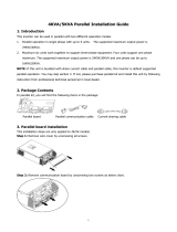
4. AMPS HP2: Box Bay Systems
The AMPS HP2 consists of a number of individual subsystems designed to work together to provide highly reli-
able, filtered power in support of the load. A typical AMPS HP2 box bay system contains the following:
1. Main Wiring Access Panel: AC input and output as
well as Safety Extra-Low Voltage (SELV) DC battery
connections are accessed through the front panel and
fed through the knockouts at the top of the rack.
2. Inverter AC Input Breaker: Serves as the main
disconnect for the inverter AC input.
3. Maintenance Bypass Switch (MBS): Can be used
to route power directly from the AC input to the AC
output, bypassing the inverter modules.
4. Inverter AC Output Breaker: Serves as the main
disconnect for the inverter AC outputs.
5. CXC Unified System Controller with integrated
Ethernet/ SNMP: Monitors and manages both
inverter and rectifier modules through a web-based
GUI and local LCD touch screen. This is a SELV
controller.
6. T2S Inverter Control Card: Communicates with the
CXC Unified controller. This is a SELV Controller.
7. Inverter Modules and shelves: Up to 9 shelves
containing 4 hot-swappable 2500 VA / 2000 W inverter
modules on each shelf.
8. Inverter Blank Modules
9. Rectifier Modules and shelves (optional): Two
shelves contain up to six hot-swappable 2400W
rectifier modules three per shelf. The rectifiers are
used as the SELV DC battery charging component of
a hybrid system.
Each rectifier shelf is only connected to one of the DC-
battery feeds: the top shelf to DC1, and the bottom
rectifier shelf is connected to DC4. In a system with
four independent battery feeds, two of these battery
banks will not be charged from the rectifiers.
10. AC Input LED: This LED is normally lit if AC input
power is available at the bypass switch. If the LED is
not lit, check the AC input.
11. Rectifier Blank Module:
Figure 7 — AMPS HP2, Large
1
2
4
3
5
7
9
6
8 8
8
8
8
8
10
11

0260080-J0 Rev B
18
4.1 Specifications AMPS HP2: Box Bay
Model
AMPS 3-75 (N+1) AMPS 3-75 (N+1) R AMPS 2-40 AMPS 2-40R
AC
Input
AC Input Voltage 120/208V 120/208V 120/208V or
120/240V
120/208V or 120/240V
Full Load inverter AC
Input Current (per phase)
190A 190A 160A 160A
Full Load rectifer AC
Input Current (per phase)
x 40A x 60A
AC Input poles & wiring 4 w + G 4 w + G 3 w + G 3 w + G
Wiring 3Φ Wye 3ΦWye 2Φ 2Φ
AC inverter input
Breaker/fuse See Note: 2
250A
3 Pole
250A
3 Pole
200A
2 Pole
200A
2 Pole
AC rectifer input Breaker/
fuse See Note: 2
x 50A
3 Pole
x 100A
2 Pole
Recommended
AC Input
Wire size,
90ºC copper
See Note: 1
Inverter 2 X2/0 2 X2/0 2x 1/0 2x 1/0
Rectifer x #6 AWG x #2 AWG
AC
Output
Total AC Output (Max) 68kVA, 54kW (n+1) 68kVA, 54kW (n+1) 40kVA, 32kW 40kVA, 32kW
AC Output Voltage 120/208V 120/208V 120/208V or
120/240V
120/208V or 120/240V
AC Output poles & wiring 4 w + G 4 w + G 3 w + G 3 w + G
Wiring 3ΦWye 3ΦWye 2Φ 2Φ
AC Output Current (per
Phase)
187�5A 187�5A 167A 167A
Installed Inverter Input &
Output Circuit Breaker
225A 225A 225A 225A
Recommended AC
Output Wire size, 90ºC
copper
See Note: 1
2 X2/0 2 X2/0 2x 1/0 2x 1/0
AC Input & Output Connection Terminals
Box lugs are rated for both Aluminum and Copper wire, 2 x 350 KCMIL to2 x #6 AWG. Fasten clamping screw to 375 in-lbs (42
N-m) for #1 AWG to 350 kcmil wire or 200 in-lbs (23 N-m) for #6 to #2 AWG wire.
Note 1 Inverter AC Input & AC Output connections: Calculations based on full load and t, 0.8 derating with 4 current carrying
conductors, (L1,L2,L3,N) @ 40 °C.
Note 2 Consult your local and national electrical codes. AC source must be limited to 10kA Short Circuit Current.
/