Yamaha 2008 Fazer FZ1-NX User manual
- Category
- Motorcycles
- Type
- User manual
This manual is also suitable for

SERVICE MANUAL
FZ1-N(X)
FZ1-S(X)
FZ1-SA
FZ1-NA
2008
5D0-28197-E1

EAS20040
FZ1-N(X)/FZ1-S(X)/FZ1-SA/FZ1-NA
SERVICE MANUAL
©2008 by Yamaha Motor Co., Ltd.
First edition, December 2007
All rights reserved.
Any reproduction or unauthorized use without
the written permission of Yamaha Motor Co.,
Ltd. is expressly prohibited.

EAS20070
NOTICE
This manual was produced by the Yamaha Motor Company, Ltd. primarily for use by Yamaha deal-
ers and their qualified mechanics. It is not possible to include all the knowledge of a mechanic in one
manual. Therefore, anyone who uses this book to perform maintenance and repairs on Yamaha
vehicles should have a basic understanding of mechanics and the techniques to repair these types
of vehicles. Repair and maintenance work attempted by anyone without this knowledge is likely to
render the vehicle unsafe and unfit for use.
This model has been designed and manufactured to perform within certain specifications in regard
to performance and emissions. Proper service with the correct tools is necessary to ensure that the
vehicle will operate as designed. If there is any question about a service procedure, it is imperative
that you contact a Yamaha dealer for any service information changes that apply to this model. This
policy is intended to provide the customer with the most satisfaction from his vehicle and to conform
to federal environmental quality objectives.
Yamaha Motor Company, Ltd. is continually striving to improve all of its models. Modifications and
significant changes in specifications or procedures will be forwarded to all authorized Yamaha deal-
ers and will appear in future editions of this manual where applicable.
NOTE:
• This Service Manual contains information regarding periodic maintenance to the emission control
system. Please read this material carefully.
• Designs and specifications are subject to change without notice.
EAS20080
IMPORTANT MANUAL INFORMATION
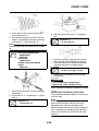
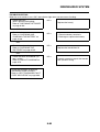
Particularly important information is distinguished in this manual by the following.
The Safety Alert Symbol means ATTENTION! BECOME ALERT! YOUR
SAFETY IS INVOLVED!
Failure to follow WARNING instructions could result in severe injury or death
to
the vehicle operator, a bystander or a person checking or repairing the vehicle.
A CAUTION indicates special precautions that must be taken to avoid damage
to the vehicle.
A NOTE provides key information to make procedures easier or clearer.
WARNING
CAUTION:
NOTE:

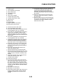
EAS20090
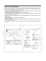
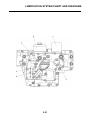
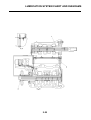
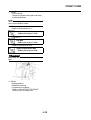
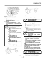
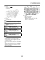
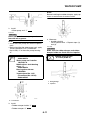
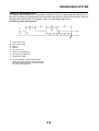
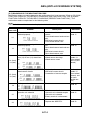
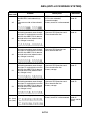
HOW TO USE THIS MANUAL
This manual is intended as a handy, easy-to-read reference book for the mechanic. Comprehensive
explanations of all installation, removal, disassembly, assembly, repair and check procedures are
laid out with the individual steps in sequential order.
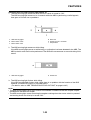
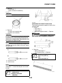
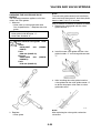
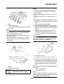
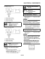
• The manual is divided into chapters and each chapter is divided into sections. The current section
title is shown at the top of each page “1”.
• Sub-section titles appear in smaller print than the section title “2”.
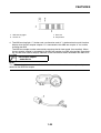
• To help identify parts and clarify procedure steps, there are exploded diagrams at the start of each
removal and disassembly section “3”.
• Numbers are given in the order of the jobs in the exploded diagram. A number indicates a disas-
sembly step “4”.
• Symbols indicate parts to be lubricated or replaced “5”.
Refer to “SYMBOLS”.
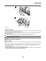
• A job instruction chart accompanies the exploded diagram, providing the order of jobs, names of
parts, notes in jobs, etc “6”.
• Jobs requiring more information (such as special tools and technical data) are described sequen-
tially “7”.

EAS20100
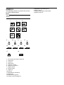
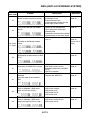
SYMBOLS
The following symbols are used in this manual
for easier understanding.
NOTE:
The following symbols are not relevant to every
vehicle.
1. Serviceable with engine mounted
2. Filling fluid
3. Lubricant
4. Special tool
5. Tightening torque
6. Wear limit, clearance
7. Engine speed
8. Electrical data
9. Engine oil
10.Gear oil
11.Molybdenum-disulfide oil
12.Brake fluid
13.Wheel-bearing grease
14.Lithium-soap-based grease
G
M
E
91011
12
B
13
LS
14
M
15
17
LT
18
New
T
R
.
.
123
456
78
16
BF
15.Molybdenum-disulfide grease
16.Silicon grease
17.Apply locking agent (LOCTITE®)
18.Replace the part


1
2
3
4
5
6
7
8
9
EAS20110
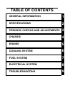
TABLE OF CONTENTS
GENERAL INFORMATION
SPECIFICATIONS
PERIODIC CHECKS AND ADJUSTMENTS
CHASSIS
ENGINE
COOLING SYSTEM
FUEL SYSTEM
ELECTRICAL SYSTEM
TROUBLESHOOTING


1
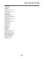
GENERAL INFORMATION
IDENTIFICATION..........................................................................................1-1
VEHICLE IDENTIFICATION NUMBER...................................................1-1
MODEL LABEL.......................................................................................1-1
FEATURES ...................................................................................................1-2
OUTLINE OF THE FI SYSTEM ..............................................................1-2
FI SYSTEM.............................................................................................1-3
INSTRUMENT FUNCTIONS ..................................................................1-4
IMPORTANT INFORMATION .....................................................................1-26
PREPARATION FOR REMOVAL AND DISASSEMBLY........................1-26
REPLACEMENT PARTS.......................................................................1-26
GASKETS, OIL SEALS AND O-RINGS................................................1-26
LOCK WASHERS/PLATES AND COTTER PINS .................................1-26
BEARINGS AND OIL SEALS ...............................................................1-27
CIRCLIPS .............................................................................................1-27
CHECKING THE CONNECTIONS .............................................................1-28
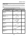
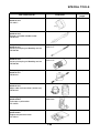
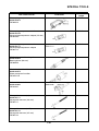
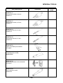
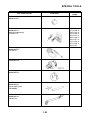
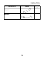
SPECIAL TOOLS........................................................................................1-29

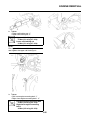
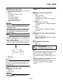
IDENTIFICATION
1-1
EAS20130
IDENTIFICATION
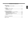
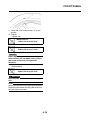
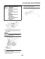
EAS20140
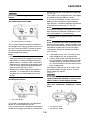
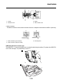
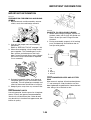
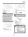
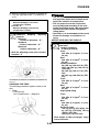
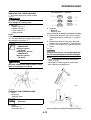
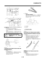
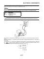
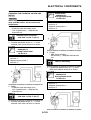
VEHICLE IDENTIFICATION NUMBER
The vehicle identification number “1” is
stamped into the right side of the steering
head pipe.
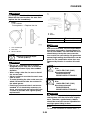
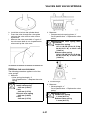
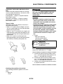
EAS20150
MODEL LABEL
The model label “1” is affixed to the frame. This
information will be needed to order spare
parts.

FEATURES
1-2
EAS20170
FEATURES
EAS5D01032
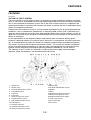
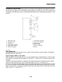
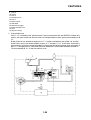
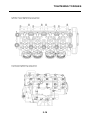
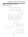
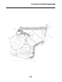
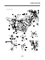
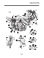
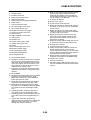
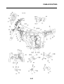
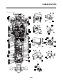
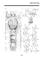
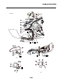
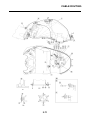
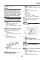
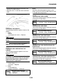
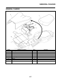
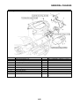
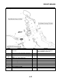
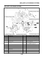
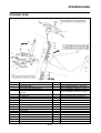
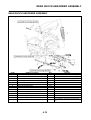
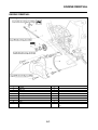
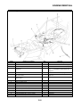
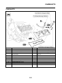
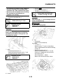
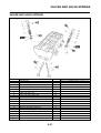
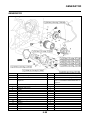
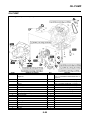
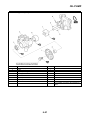
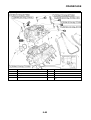
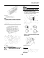
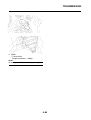
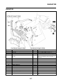
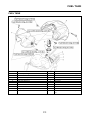
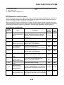
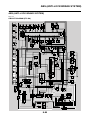
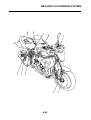
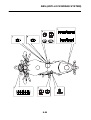
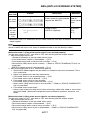
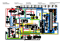
OUTLINE OF THE FI SYSTEM
The main function of a fuel supply system is to provide fuel to the combustion chamber at the opti-
mum air-fuel ratio in accordance with the engine operating conditions and the atmospheric tempera-
ture. In the conventional carburetor system, the air-fuel ratio of the mixture that is supplied to the
combustion chamber is created by the volume of the intake air and the fuel that is metered by the jet
used in the respective carburetor.
Despite the same volume of intake air, the fuel volume requirement varies by the engine operating
conditions, such as acceleration, deceleration, or operating under a heavy load. Carburetors that
meter the fuel through the use of jets have been provided with various auxiliary devices, so that an
optimum air-fuel ratio can be achieved to accommodate the constant changes in the operating con-
ditions of the engine.
As the requirements for the engine to deliver more performance and cleaner exhaust gases
increase, it becomes necessary to control the air-fuel ratio in a more precise and finely tuned man-
ner. To accommodate this need, this model has adopted an electronically controlled fuel injection
(FI) system, in place of the conventional carburetor system. This system can achieve an optimum
air-fuel ratio required by the engine at all times by using a microprocessor that regulates the fuel
injection volume according to the engine operating conditions detected by various sensors.
The adoption of the FI system has resulted in a highly precise fuel supply, improved engine
response, better fuel economy, and reduced exhaust emissions.
1. Ignition coil
2. Air filter case
3. Intake air temperature sensor
4. Fuel delivery hose
5. Fuel tank
6. Fuel pump
7. Intake air pressure sensor
8. Throttle position sensor
9. Sub-throttle position sensor
10.Fuel injector
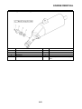
11.Catalytic converter
12.Crankshaft position sensor
13.Coolant temperature sensor
14.Spark plug
15.Cylinder identification sensor
16.Battery
17.ECU
18.Atmospheric pressure sensor
19.Relay unit (fuel pump relay)
20.Engine trouble warning light
21.Lean angle sensor
22.Air cut-off valve
23.O
2
sensor

FEATURES
1-3
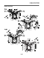
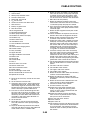
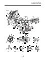
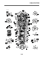
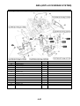
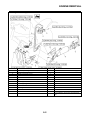
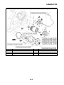
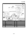
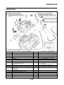
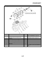
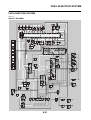
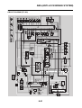
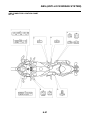
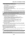
EAS5D01013
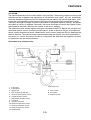
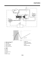
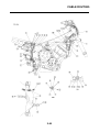
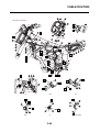
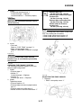
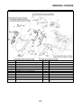
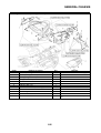
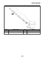
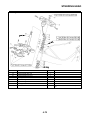
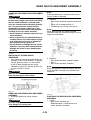
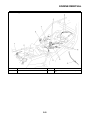
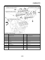
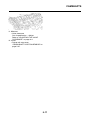
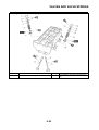
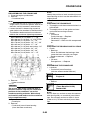
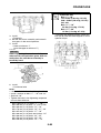
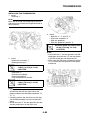
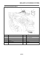
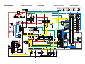
FI SYSTEM
The fuel pump delivers fuel to the fuel injector via the fuel filter. The pressure regulator maintains the
fuel pressure that is applied to the fuel injector at only 324 kPa (3.24 kg/cm
2
, 46.1 psi). Accordingly,
when the energizing signal from the ECU energizes the fuel injector, the fuel passage opens, caus-
ing the fuel to be injected into the intake manifold only during the time the passage remain open.
Therefore, the longer the length of time the fuel injector is energized (injection duration), the greater
the volume of fuel that is supplied. Conversely, the shorter the length of time the fuel injector is ener-
gized (injection duration), the lesser the volume of fuel that is supplied.
The injection duration and the injection timing are controlled by the ECU. Signals that are input from
the throttle position sensor, crankshaft position sensor, intake air pressure sensor, air temperature
sensor, coolant temperature sensor, speed sensor and O
2
sensor enable the ECU to determine the
injection duration. The injection timing is determined through the signals from the crankshaft posi-
tion sensor. As a result, the volume of fuel that is required by the engine can be supplied at all times
in accordance with the driving conditions.
Illustration is for reference only.
1. Fuel pump
2. Fuel injector
3. Ignition coil
4. ECU (engine control unit)
5. Intake air temperature sensor
6. Throttle position sensor
7. Sub-throttle position sensor
8. O
2
sensor
9. Catalytic converter
10.Coolant temperature sensor
11.Crankshaft position sensor
12.Intake air pressure sensor
13.Throttle body
14.Air filter case
A. Fuel system
B. Air system
C. Control system

FEATURES
1-4
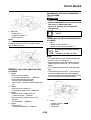
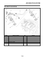
EAS5D01014
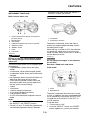
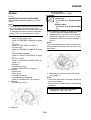
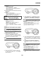
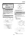
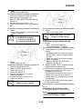
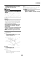
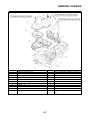
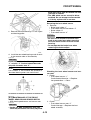
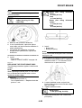
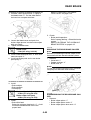
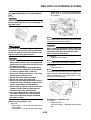
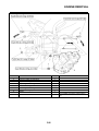
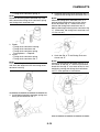
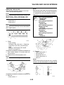
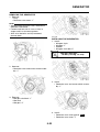
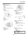
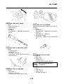
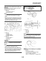
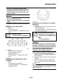
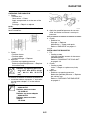
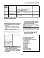
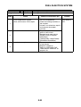
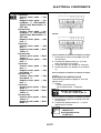
INSTRUMENT FUNCTIONS
Multi-function meter unit
WARNING
EWA5D01011
Be sure to stop the vehicle before making
any setting changes to the multi-function
meter unit.
The multi-function meter unit is equipped with
the following:
• a speedometer (which shows the riding
speed)
• a tachometer (which shows engine speed)
• an odometer (which shows the total distance
traveled)
• two tripmeters (which show the distance trav-
eled since they were last set to zero)
• a fuel reserve tripmeter (which shows the
distance traveled since the left segment of
the fuel meter started flashing)
•a clock
• a fuel meter
• a coolant temperature display
• an air intake temperature display
• a self-diagnosis device
• an LCD and tachometer brightness control
mode
NOTE:
• Be sure to turn the key to “ON” before using
the “SELECT” and “RESET” buttons.
• For the U.K. only: To switch the speedometer
and odometer/tripmeter displays between
kilometers and miles, press the “SELECT”
button for at least one second.
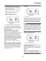
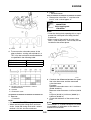
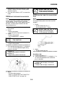
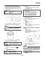
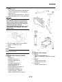
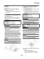
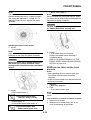
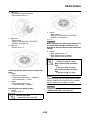
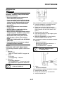
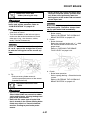
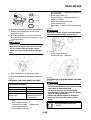
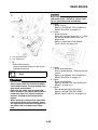
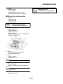
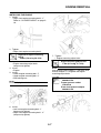
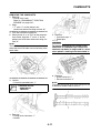
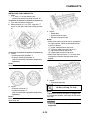
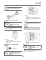
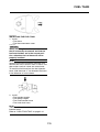
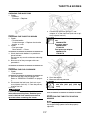
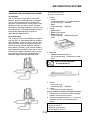
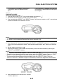
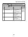
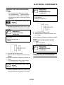
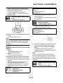
Tachometer
The electric tachometer allows the rider to
monitor the engine speed and keep it within
the ideal power range.
When the key is turned to “ON”, the tachome-
ter needle will sweep once across the r/min
range and then return to zero r/min in order to
test the electrical circuit.
CAUTION:
ECA5D01015
Do not operate the engine in the tachome-
ter red zone.
Red zone: 12000 r/min and above
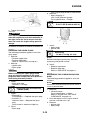
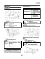
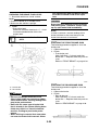
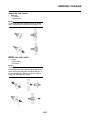
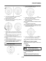
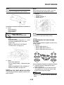
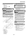
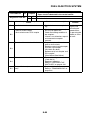
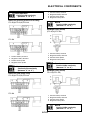
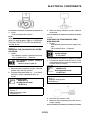
Clock mode
The clock is displayed when the key is turned
to “ON”. In addition, the clock can be displayed
for 10 seconds by pushing the “SELECT” but-
ton when the main switch is in the “OFF” or
“LOCK” position.
To set the clock
1. Turn the key to “ON”.
2. Push the “SELECT” button and “RESET”
button together for at least two seconds.
1. Coolant temperature display/air intake tem-
perature display
2. Speedometer
3. Tachometer
4. Odometer/tripmeter/fuel reserve tripmeter
5. “SELECT” button
6. “RESET” button
7. Clock
8. Fuel meter
1. Tachometer
2. Tachometer red zone
1. Clock
2. Speedometer

FEATURES
1-5
3. When the hour digits start flashing, push
the “RESET” button to set the hours.
4. Push the “SELECT” button, and the minute
digits will start flashing.
5. Push the “RESET” button to set the min-
utes.
6. Push the “SELECT” button and then
release it to start the clock.
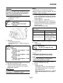
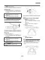
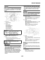
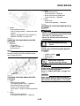
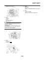
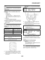
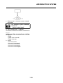
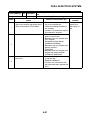
Odometer and tripmeter modes
Push the “SELECT” button to switch the dis-
play between the odometer mode “ODO” and
the tripmeter modes “TRIP A” and “TRIP B” in
the following order:
TRIP A → TRIP B → ODO → TRIP A
When the fuel amount in the fuel tank
decreases to 3.4 L (0.90 US gal) (0.75
Imp.gal), the left segment of the fuel meter will
start flashing, and the odometer display will
automatically change to the fuel reserve
tripmeter mode “FTRIP” and start counting the
distance traveled from that point. In that case,
push the “SELECT” button to switch the dis-
play between the various tripmeter and odom-
eter modes in the following order:
F-TRIP → TRIP A → TRIP B → ODO → F-
TRIP
To reset a tripmeter, select it by pushing the
“SELECT” button, and then push the “RESET”
button for at least one second. If you do not
reset the fuel reserve tripmeter manually, it will
reset itself automatically and the display will
return to the prior mode after refueling and
traveling 5 km (3 mi).
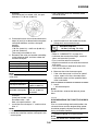
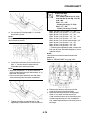
Fuel meter
The fuel meter indicates the amount of fuel in
the fuel tank. The display segments of the fuel
meter disappear towards “E” (Empty) as the
fuel level decreases. When only one segment
is left near “E”, refuel as soon as possible.
NOTE:
This fuel meter is equipped with a self-diagno-
sis system. If the electrical circuit is defective,
the following cycle will be repeated until the
malfunction is corrected: “E” (Empty), “F” (Full)
and symbol “ ” will flash eight times, then go
off for approximately 3 seconds. If this occurs,
have a Yamaha dealer check the electrical cir-
cuit.
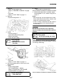
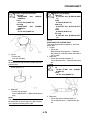
Coolant temperature mode
The coolant temperature display indicates the
temperature of the coolant.
Push the “RESET” button to switch the coolant
temperature display to the air intake tempera-
ture display.
NOTE:
When the coolant temperature display is
selected, “C” is displayed for one second, and
then the coolant temperature is displayed.
1. Odometer/tripmeter/fuel reserve tripmeter
1. Fuel meter
1. Coolant temperature display

FEATURES
1-6
CAUTION:
ECA5D01023
Do not operate the engine if it is over-
heated.
Air intake temperature mode
The air intake temperature display indicates
the temperature of the air drawn into the air fil-
ter case. Push the “RESET” button to switch
the coolant temperature display to the air
intake temperature display.
NOTE:
• Even if the air intake temperature is set to be
displayed, the coolant temperature warning
light comes on when the engine overheats.
• When the key is turned to “ON”, the coolant
temperature is automatically displayed, even
if the air intake temperature was displayed
prior to turning the key to “OFF”.
• When the air intake temperature display is
selected, “A” is displayed for one second,
and then the air intake temperature is dis-
played.
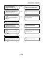
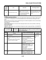
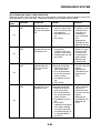
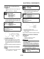
Self-diagnosis device
This model is equipped with a self-diagnosis
device for various electrical circuits.
If any of those circuits are defective, the engine
trouble warning light will come on, and then the
display will indicate a two-digit error code (e.g.,
11, 12, 13).
This model is also equipped with a self-diagno-
sis device for the immobilizer system.
If any of the immobilizer system circuits are
defective, the immobilizer system indicator
light will flash, and then the display will indicate
a two-digit error code (e.g., 51, 52, 53).
NOTE:
If the display indicates error code 52, this could
be caused by transponder interference. If this
error code appears, try the following.
1. Use the code re-registering key to start the
engine.
NOTE:
Make sure there are no other immobilizer keys
close to the main switch, and do not keep more
than one immobilizer key on the same key ring!
Immobilizer system keys may cause signal
interference, which may prevent the engine
from starting
2. If the engine starts, turn it off and try start-
ing the engine with the standard keys.
3. If one or both of the standard keys do not
start the engine, take the vehicle, the code
re-registering key and both standard keys
to a Yamaha dealer and have the standard
keys re-registered.
If the display indicates any error codes, note
the code number, and then have a Yamaha
dealer check the vehicle.
CAUTION:
ECA5D01024
If the display indicates an error code, the
vehicle should be checked as soon as pos-
sible in order to avoid engine damage.
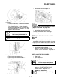
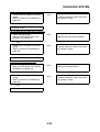
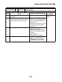
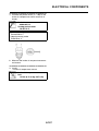
LCD and tachometer brightness control
mode
1. Air intake temperature display
1. Error code display
1. Tachometer panel
2. Tachometer needle

FEATURES
1-7
This function allows you to adjust the bright-
ness of the LCD and the tachometer panel and
needle to suit the outside lighting conditions.
To set the brightness
1. Turn the key to “OFF”.
2. Push and hold the “SELECT” button.
3. Turn the key to “ON”, and then release the
“SELECT” button after five seconds.
4. Push the “RESET” button to select the
desired brightness level.
5. Push the “SELECT” button to confirm the
selected brightness level. The display will
return to the odometer or tripmeter mode.
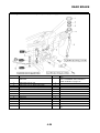
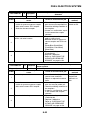
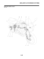
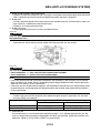
EAS5D01001
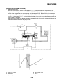
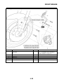
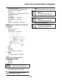
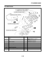
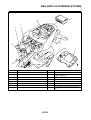
OUTLINE OF THE ABS
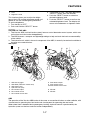
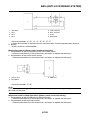
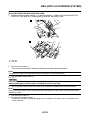
1. The Yamaha ABS (anti-lock brake system) features a dual electronic control system, which acts
on the front and rear brakes independently.
2. The ABS features a compact and lightweight design to help maintain the basic maneuverability
of the vehicle.
3. The hydraulic unit, which is the main component of the ABS, is centrally located on the vehicle to
increase mass centralization.
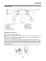
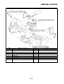
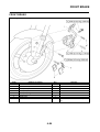
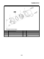
ABS layout
ABS
The operation of the Yamaha ABS brakes is the same as conventional brakes on other vehicles, with
a brake lever for operating the front brake and a brake pedal for operating the rear brake.
When wheel lock is detected during emergency braking, hydraulic control is performed by the
hydraulic system on the front and rear brakes independently.
3. LCD
4. Brightness level
1. ABS warning light
2. ABS ECU (electronic control unit)
3. ABS motor relay
4. Hydraulic unit (HU)
5. Rear brake caliper
6. Rear wheel sensor
7. Rear wheel sensor rotor
8. Front brake caliper
9. Front wheel sensor
10.Front wheel sensor rotor
A. FZ1-NA
B. FZ1-SA

FEATURES
1-8
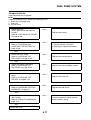
Useful terms
• Wheel speed:
The rotation speed of the front and rear wheels.
• Chassis speed:
The speed of the chassis.
When the brakes are applied, wheel speed and chassis speed are reduced. However, the chassis
travels forward by its inertia even though the wheel speed is reduced.
•Brake force:
The force applied by braking to reduce the wheel speed.
• Wheel lock:
A condition that occurs when the rotation of one or both of the wheels has stopped, but the vehicle
continues to travel.
• Side force:
The force on the tires which supports the vehicle when cornering.
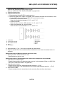
• Slip ratio:
When the brakes are applied, slipping occurs between the tires and the road surface. This causes
a difference between the wheel speed and the chassis speed. Slip ratio is the value that shows the
rate of wheel slippage and is defined by the following formula.
0%: There is no slipping between the wheel and the road surface. The chassis speed is equal to
the wheel speed.
100%: The wheel speed is “0”, but the chassis is moving (i.e., wheel lock).
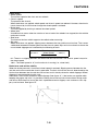
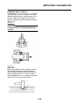
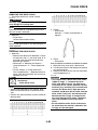
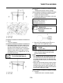
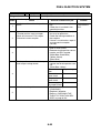
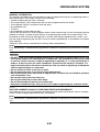
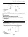
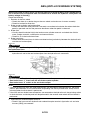
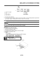
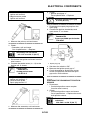
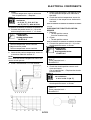
Brake force and vehicle stability
When the brake pressure is increased, wheel speed is reduced. Slipping occurs between the tire
and the road surface and brake force is generated. The limit of this brake force is determined by the
friction force between the tire and the road surface and is closely related to wheel slippage. Wheel
slippage is represented by the slip ratio.
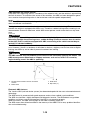
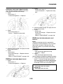
Side force is also closely related to wheel slippage. See figure “A”. If the brakes are applied while
keeping the proper slip ratio, it is possible to obtain the maximum brake force without losing much
side force. ABS allows full use of the tires’ capabilities even on slippery road surfaces or less slip-
pery road surfaces. See figure “B”.
Slip ratio =
Chassis speed
– Wheel speed
× 100 (%)
Chassis speed

FEATURES
1-9
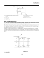
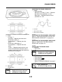
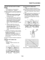
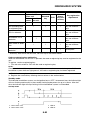
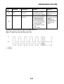
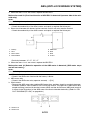
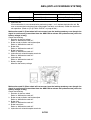
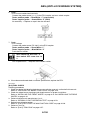
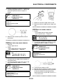
Wheel slip and hydraulic control
The ABS ECU calculates the wheel speed of each wheel according to the rotation signal received
from the front and rear wheel sensors. In addition, the ABS ECU calculates the vehicle chassis
speed and the rate of speed reduction based on the wheel speed values.
The difference between the chassis speed and the wheel speed calculated in the slip ratio formula is
equal to the wheel slip. When the wheel speed is suddenly reduced, the wheel has a tendency to
lock. When the wheel slip and the wheel speed reduction rate exceed the preset values, the ABS
ECU determines that the wheel has a tendency to lock.
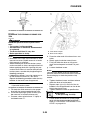
If the slip is large and the wheel has a tendency to lock (point A in the following figure), the ABS
ECU reduces the brake fluid pressure in the brake caliper. The ABS ECU increases the pressure of
the brake fluid in the brake caliper when the tendency to lock has diminished (point B in the following
figure).
a. Friction force between the tire and road
surface
b. Brake force
c. Side force
d. Slip ratio (%)
e. Less slippery road surface
f. Controlling zone
g. Slippery road surface
a. Vehicle speed
b. Wheel speed
c. Pressurized
d. Depressurized
e. Brake force

FEATURES
1-10
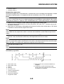
ABS operation and vehicle control
If the ABS starts operating, there is a tendency of the wheel to lock, and the vehicle is approaching
the limit of control. To make the rider aware of this condition, the ABS has been designed to gener-
ate a reaction-force pulsating action in the brake lever and brake pedal independently.
NOTE:
When the ABS is activated, a pulsating action may be felt at the brake lever or brake pedal, but this
does not indicate a malfunction.
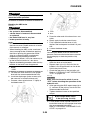
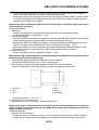
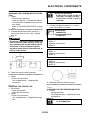
The higher the side force on a tire, the less traction there is available for braking. This is true
whether the vehicle is equipped with ABS or not. Therefore, sudden braking while cornering is not
recommended. Excessive side force, which ABS cannot prevent, could cause the tire to slip side-
ways.
WARNING
EWA5D01001
The braking of the vehicle, even in the worst case, is principally executed when the vehicle is
advancing straight ahead. During a turn, sudden braking is liable to cause a loss of traction
of the tires. Even in vehicles equipped with ABS, overturning of the vehicle cannot be pre-
vented if it is braked suddenly.
The ABS functions to prevent the tendency of the wheel to lock by controlling the brake fluid pres-
sure. However, if there is a tendency of the wheel to lock on a slippery road surface, due to engine
braking, the ABS may not be able to prevent the wheel from locking.
WARNING
EWA13870
The ABS controls only the tendency of the wheel to lock caused by applying the brakes. The
ABS cannot prevent wheel lock on slippery surfaces, such as ice, when it is caused by
engine braking, even if the ABS is operating.
Electronic ABS features
The Yamaha ABS (anti-lock brake system) has been developed with the most advanced electronic
technology.
The ABS control is processed with good response under various vehicle travel conditions.
The ABS also includes a highly developed self-diagnosis function. The ABS detects any problem
condition and allows normal braking even if the ABS is not operating properly.
When this occurs, the ABS warning light on the meter assembly comes on.
The ABS stores the malfunction codes in the memory of the ABS ECU for easy problem identifica-
tion and troubleshooting.
a. Friction force between the tire and road
surface
b. Brake force
c. Side force
d. Slip ratio (%)

FEATURES
1-11
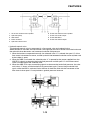
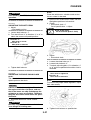
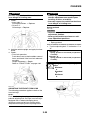
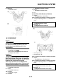
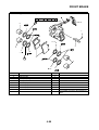
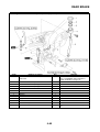
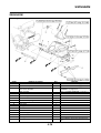
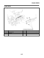
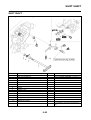
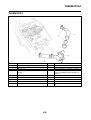
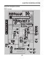
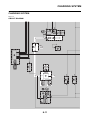
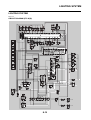
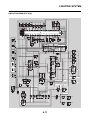
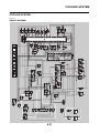
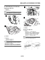
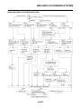
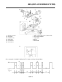
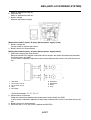
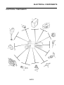
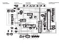
ABS block diagram
EAS5D01002
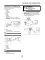
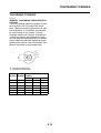
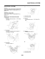
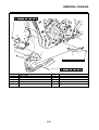
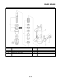
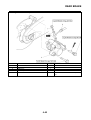
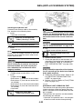
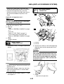
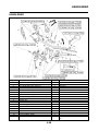
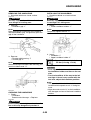
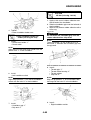
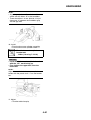
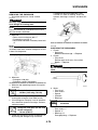
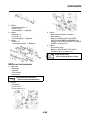
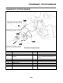
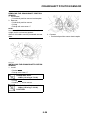
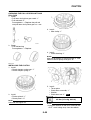
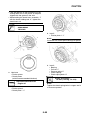
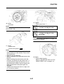
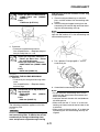
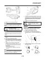
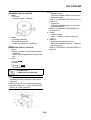
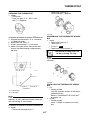
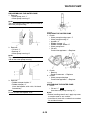
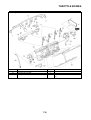
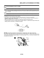
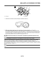
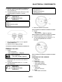
ABS COMPONENT FUNCTIONS
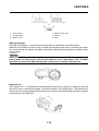
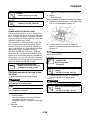
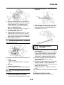
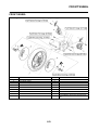
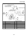
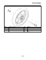
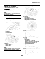
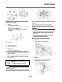
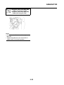
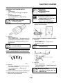
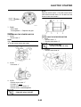
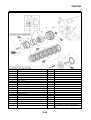
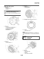
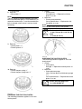
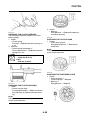
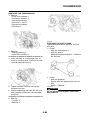
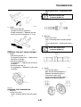
Wheel sensors and wheel sensor rotors
Wheel sensors “1” detect the wheel rotation speed and transmit the wheel rotation signal to the ABS
ECU.
Each wheel sensor is composed of a permanent magnet and a hall IC. The wheel sensors are
installed in the sensor housing for each wheel.
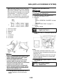
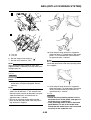
Sensor rotor “2” is pressed in the inner side of the front wheel hub and rotate with the wheel.
Sensor rotor “3” is install on the rear hub and rotate with the wheel. The sensor rotors have 42/front,
44/rear serrations inside and are installed close to the wheel sensors. As the sensor rotor rotates,
the hall element in the hall IC installed in the wheel sensor generates the voltage which is propor-
tional to the magnetic flux density, and the generated voltage is processed for waveform shaping in
the hall IC to output.
The ABS ECU calculates the wheel rotation speed by detecting the frequency of this voltage.
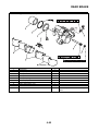
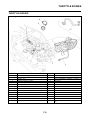
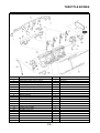
1. Rear brake master cylinder
2. Hydraulic unit
3. Hydraulic pump
4. ABS motor
5. Buffer chamber
6. Hydraulic control valve
7. Front brake master cylinder
8. Rear brake caliper
9. Front brake caliper
10.ABS ECU
11.Rear wheel sensor
12.Front wheel sensor
13.ABS warning light
Page is loading ...
Page is loading ...
Page is loading ...
Page is loading ...
Page is loading ...
Page is loading ...
Page is loading ...
Page is loading ...
Page is loading ...
Page is loading ...
Page is loading ...
Page is loading ...
Page is loading ...
Page is loading ...
Page is loading ...
Page is loading ...
Page is loading ...
Page is loading ...
Page is loading ...
Page is loading ...
Page is loading ...
Page is loading ...
Page is loading ...
Page is loading ...
Page is loading ...
Page is loading ...
Page is loading ...
Page is loading ...
Page is loading ...
Page is loading ...
Page is loading ...
Page is loading ...
Page is loading ...
Page is loading ...
Page is loading ...
Page is loading ...
Page is loading ...
Page is loading ...
Page is loading ...
Page is loading ...
Page is loading ...
Page is loading ...
Page is loading ...
Page is loading ...
Page is loading ...
Page is loading ...
Page is loading ...
Page is loading ...
Page is loading ...
Page is loading ...
Page is loading ...
Page is loading ...
Page is loading ...
Page is loading ...
Page is loading ...
Page is loading ...
Page is loading ...
Page is loading ...
Page is loading ...
Page is loading ...
Page is loading ...
Page is loading ...
Page is loading ...
Page is loading ...
Page is loading ...
Page is loading ...
Page is loading ...
Page is loading ...
Page is loading ...
Page is loading ...
Page is loading ...
Page is loading ...
Page is loading ...
Page is loading ...
Page is loading ...
Page is loading ...
Page is loading ...
Page is loading ...
Page is loading ...
Page is loading ...
Page is loading ...
Page is loading ...
Page is loading ...
Page is loading ...
Page is loading ...
Page is loading ...
Page is loading ...
Page is loading ...
Page is loading ...
Page is loading ...
Page is loading ...
Page is loading ...
Page is loading ...
Page is loading ...
Page is loading ...
Page is loading ...
Page is loading ...
Page is loading ...
Page is loading ...
Page is loading ...
Page is loading ...
Page is loading ...
Page is loading ...
Page is loading ...
Page is loading ...
Page is loading ...
Page is loading ...
Page is loading ...
Page is loading ...
Page is loading ...
Page is loading ...
Page is loading ...
Page is loading ...
Page is loading ...
Page is loading ...
Page is loading ...
Page is loading ...
Page is loading ...
Page is loading ...
Page is loading ...
Page is loading ...
Page is loading ...
Page is loading ...
Page is loading ...
Page is loading ...
Page is loading ...
Page is loading ...
Page is loading ...
Page is loading ...
Page is loading ...
Page is loading ...
Page is loading ...
Page is loading ...
Page is loading ...
Page is loading ...
Page is loading ...
Page is loading ...
Page is loading ...
Page is loading ...
Page is loading ...
Page is loading ...
Page is loading ...
Page is loading ...
Page is loading ...
Page is loading ...
Page is loading ...
Page is loading ...
Page is loading ...
Page is loading ...
Page is loading ...
Page is loading ...
Page is loading ...
Page is loading ...
Page is loading ...
Page is loading ...
Page is loading ...
Page is loading ...
Page is loading ...
Page is loading ...
Page is loading ...
Page is loading ...
Page is loading ...
Page is loading ...
Page is loading ...
Page is loading ...
Page is loading ...
Page is loading ...
Page is loading ...
Page is loading ...
Page is loading ...
Page is loading ...
Page is loading ...
Page is loading ...
Page is loading ...
Page is loading ...
Page is loading ...
Page is loading ...
Page is loading ...
Page is loading ...
Page is loading ...
Page is loading ...
Page is loading ...
Page is loading ...
Page is loading ...
Page is loading ...
Page is loading ...
Page is loading ...
Page is loading ...
Page is loading ...
Page is loading ...
Page is loading ...
Page is loading ...
Page is loading ...
Page is loading ...
Page is loading ...
Page is loading ...
Page is loading ...
Page is loading ...
Page is loading ...
Page is loading ...
Page is loading ...
Page is loading ...
Page is loading ...
Page is loading ...
Page is loading ...
Page is loading ...
Page is loading ...
Page is loading ...
Page is loading ...
Page is loading ...
Page is loading ...
Page is loading ...
Page is loading ...
Page is loading ...
Page is loading ...
Page is loading ...
Page is loading ...
Page is loading ...
Page is loading ...
Page is loading ...
Page is loading ...
Page is loading ...
Page is loading ...
Page is loading ...
Page is loading ...
Page is loading ...
Page is loading ...
Page is loading ...
Page is loading ...
Page is loading ...
Page is loading ...
Page is loading ...
Page is loading ...
Page is loading ...
Page is loading ...
Page is loading ...
Page is loading ...
Page is loading ...
Page is loading ...
Page is loading ...
Page is loading ...
Page is loading ...
Page is loading ...
Page is loading ...
Page is loading ...
Page is loading ...
Page is loading ...
Page is loading ...
Page is loading ...
Page is loading ...
Page is loading ...
Page is loading ...
Page is loading ...
Page is loading ...
Page is loading ...
Page is loading ...
Page is loading ...
Page is loading ...
Page is loading ...
Page is loading ...
Page is loading ...
Page is loading ...
Page is loading ...
Page is loading ...
Page is loading ...
Page is loading ...
Page is loading ...
Page is loading ...
Page is loading ...
Page is loading ...
Page is loading ...
Page is loading ...
Page is loading ...
Page is loading ...
Page is loading ...
Page is loading ...
Page is loading ...
Page is loading ...
Page is loading ...
Page is loading ...
Page is loading ...
Page is loading ...
Page is loading ...
Page is loading ...
Page is loading ...
Page is loading ...
Page is loading ...
Page is loading ...
Page is loading ...
Page is loading ...
Page is loading ...
Page is loading ...
Page is loading ...
Page is loading ...
Page is loading ...
Page is loading ...
Page is loading ...
Page is loading ...
Page is loading ...
Page is loading ...
Page is loading ...
Page is loading ...
Page is loading ...
Page is loading ...
Page is loading ...
Page is loading ...
Page is loading ...
Page is loading ...
Page is loading ...
Page is loading ...
Page is loading ...
Page is loading ...
Page is loading ...
Page is loading ...
Page is loading ...
Page is loading ...
Page is loading ...
Page is loading ...
Page is loading ...
Page is loading ...
Page is loading ...
Page is loading ...
Page is loading ...
Page is loading ...
Page is loading ...
Page is loading ...
Page is loading ...
Page is loading ...
Page is loading ...
Page is loading ...
Page is loading ...
Page is loading ...
Page is loading ...
Page is loading ...
Page is loading ...
Page is loading ...
Page is loading ...
Page is loading ...
Page is loading ...
Page is loading ...
Page is loading ...
Page is loading ...
Page is loading ...
Page is loading ...
Page is loading ...
Page is loading ...
Page is loading ...
Page is loading ...
Page is loading ...
Page is loading ...
Page is loading ...
Page is loading ...
Page is loading ...
Page is loading ...
Page is loading ...
Page is loading ...
Page is loading ...
Page is loading ...
Page is loading ...
Page is loading ...
Page is loading ...
Page is loading ...
Page is loading ...
Page is loading ...
Page is loading ...
Page is loading ...
Page is loading ...
Page is loading ...
Page is loading ...
Page is loading ...
Page is loading ...
Page is loading ...
Page is loading ...
Page is loading ...
Page is loading ...
Page is loading ...
Page is loading ...
Page is loading ...
Page is loading ...
Page is loading ...
Page is loading ...
Page is loading ...
Page is loading ...
Page is loading ...
Page is loading ...
Page is loading ...
Page is loading ...
Page is loading ...
Page is loading ...
Page is loading ...
Page is loading ...
Page is loading ...
Page is loading ...
Page is loading ...
Page is loading ...
Page is loading ...
Page is loading ...
Page is loading ...
Page is loading ...
Page is loading ...
Page is loading ...
Page is loading ...
Page is loading ...
Page is loading ...
Page is loading ...
Page is loading ...
Page is loading ...
Page is loading ...
Page is loading ...
Page is loading ...
Page is loading ...
Page is loading ...
Page is loading ...
Page is loading ...
Page is loading ...
Page is loading ...
Page is loading ...
Page is loading ...
Page is loading ...
Page is loading ...
Page is loading ...
Page is loading ...
Page is loading ...
Page is loading ...
Page is loading ...
Page is loading ...
Page is loading ...
Page is loading ...
Page is loading ...
Page is loading ...
Page is loading ...
Page is loading ...
Page is loading ...
Page is loading ...
Page is loading ...
Page is loading ...
Page is loading ...
Page is loading ...
Page is loading ...
Page is loading ...
Page is loading ...
Page is loading ...
Page is loading ...
Page is loading ...
Page is loading ...
Page is loading ...
Page is loading ...
Page is loading ...
Page is loading ...
Page is loading ...
Page is loading ...
Page is loading ...
Page is loading ...
Page is loading ...
Page is loading ...
Page is loading ...
Page is loading ...
Page is loading ...
Page is loading ...
Page is loading ...
Page is loading ...
Page is loading ...
Page is loading ...
Page is loading ...
Page is loading ...
Page is loading ...
Page is loading ...
Page is loading ...
Page is loading ...
Page is loading ...
Page is loading ...
Page is loading ...
Page is loading ...
Page is loading ...
Page is loading ...
Page is loading ...
Page is loading ...
Page is loading ...
Page is loading ...
Page is loading ...
Page is loading ...
Page is loading ...
Page is loading ...
Page is loading ...
Page is loading ...
Page is loading ...
Page is loading ...
Page is loading ...
Page is loading ...
Page is loading ...
Page is loading ...
Page is loading ...
Page is loading ...
Page is loading ...
Page is loading ...
Page is loading ...
Page is loading ...
Page is loading ...
Page is loading ...
Page is loading ...
Page is loading ...
Page is loading ...
Page is loading ...
Page is loading ...
Page is loading ...
Page is loading ...
Page is loading ...
Page is loading ...
Page is loading ...
Page is loading ...
Page is loading ...
Page is loading ...
Page is loading ...
Page is loading ...
Page is loading ...
Page is loading ...
Page is loading ...
Page is loading ...
Page is loading ...
Page is loading ...
Page is loading ...
Page is loading ...
Page is loading ...
Page is loading ...
Page is loading ...
Page is loading ...
-
 1
1
-
 2
2
-
 3
3
-
 4
4
-
 5
5
-
 6
6
-
 7
7
-
 8
8
-
 9
9
-
 10
10
-
 11
11
-
 12
12
-
 13
13
-
 14
14
-
 15
15
-
 16
16
-
 17
17
-
 18
18
-
 19
19
-
 20
20
-
 21
21
-
 22
22
-
 23
23
-
 24
24
-
 25
25
-
 26
26
-
 27
27
-
 28
28
-
 29
29
-
 30
30
-
 31
31
-
 32
32
-
 33
33
-
 34
34
-
 35
35
-
 36
36
-
 37
37
-
 38
38
-
 39
39
-
 40
40
-
 41
41
-
 42
42
-
 43
43
-
 44
44
-
 45
45
-
 46
46
-
 47
47
-
 48
48
-
 49
49
-
 50
50
-
 51
51
-
 52
52
-
 53
53
-
 54
54
-
 55
55
-
 56
56
-
 57
57
-
 58
58
-
 59
59
-
 60
60
-
 61
61
-
 62
62
-
 63
63
-
 64
64
-
 65
65
-
 66
66
-
 67
67
-
 68
68
-
 69
69
-
 70
70
-
 71
71
-
 72
72
-
 73
73
-
 74
74
-
 75
75
-
 76
76
-
 77
77
-
 78
78
-
 79
79
-
 80
80
-
 81
81
-
 82
82
-
 83
83
-
 84
84
-
 85
85
-
 86
86
-
 87
87
-
 88
88
-
 89
89
-
 90
90
-
 91
91
-
 92
92
-
 93
93
-
 94
94
-
 95
95
-
 96
96
-
 97
97
-
 98
98
-
 99
99
-
 100
100
-
 101
101
-
 102
102
-
 103
103
-
 104
104
-
 105
105
-
 106
106
-
 107
107
-
 108
108
-
 109
109
-
 110
110
-
 111
111
-
 112
112
-
 113
113
-
 114
114
-
 115
115
-
 116
116
-
 117
117
-
 118
118
-
 119
119
-
 120
120
-
 121
121
-
 122
122
-
 123
123
-
 124
124
-
 125
125
-
 126
126
-
 127
127
-
 128
128
-
 129
129
-
 130
130
-
 131
131
-
 132
132
-
 133
133
-
 134
134
-
 135
135
-
 136
136
-
 137
137
-
 138
138
-
 139
139
-
 140
140
-
 141
141
-
 142
142
-
 143
143
-
 144
144
-
 145
145
-
 146
146
-
 147
147
-
 148
148
-
 149
149
-
 150
150
-
 151
151
-
 152
152
-
 153
153
-
 154
154
-
 155
155
-
 156
156
-
 157
157
-
 158
158
-
 159
159
-
 160
160
-
 161
161
-
 162
162
-
 163
163
-
 164
164
-
 165
165
-
 166
166
-
 167
167
-
 168
168
-
 169
169
-
 170
170
-
 171
171
-
 172
172
-
 173
173
-
 174
174
-
 175
175
-
 176
176
-
 177
177
-
 178
178
-
 179
179
-
 180
180
-
 181
181
-
 182
182
-
 183
183
-
 184
184
-
 185
185
-
 186
186
-
 187
187
-
 188
188
-
 189
189
-
 190
190
-
 191
191
-
 192
192
-
 193
193
-
 194
194
-
 195
195
-
 196
196
-
 197
197
-
 198
198
-
 199
199
-
 200
200
-
 201
201
-
 202
202
-
 203
203
-
 204
204
-
 205
205
-
 206
206
-
 207
207
-
 208
208
-
 209
209
-
 210
210
-
 211
211
-
 212
212
-
 213
213
-
 214
214
-
 215
215
-
 216
216
-
 217
217
-
 218
218
-
 219
219
-
 220
220
-
 221
221
-
 222
222
-
 223
223
-
 224
224
-
 225
225
-
 226
226
-
 227
227
-
 228
228
-
 229
229
-
 230
230
-
 231
231
-
 232
232
-
 233
233
-
 234
234
-
 235
235
-
 236
236
-
 237
237
-
 238
238
-
 239
239
-
 240
240
-
 241
241
-
 242
242
-
 243
243
-
 244
244
-
 245
245
-
 246
246
-
 247
247
-
 248
248
-
 249
249
-
 250
250
-
 251
251
-
 252
252
-
 253
253
-
 254
254
-
 255
255
-
 256
256
-
 257
257
-
 258
258
-
 259
259
-
 260
260
-
 261
261
-
 262
262
-
 263
263
-
 264
264
-
 265
265
-
 266
266
-
 267
267
-
 268
268
-
 269
269
-
 270
270
-
 271
271
-
 272
272
-
 273
273
-
 274
274
-
 275
275
-
 276
276
-
 277
277
-
 278
278
-
 279
279
-
 280
280
-
 281
281
-
 282
282
-
 283
283
-
 284
284
-
 285
285
-
 286
286
-
 287
287
-
 288
288
-
 289
289
-
 290
290
-
 291
291
-
 292
292
-
 293
293
-
 294
294
-
 295
295
-
 296
296
-
 297
297
-
 298
298
-
 299
299
-
 300
300
-
 301
301
-
 302
302
-
 303
303
-
 304
304
-
 305
305
-
 306
306
-
 307
307
-
 308
308
-
 309
309
-
 310
310
-
 311
311
-
 312
312
-
 313
313
-
 314
314
-
 315
315
-
 316
316
-
 317
317
-
 318
318
-
 319
319
-
 320
320
-
 321
321
-
 322
322
-
 323
323
-
 324
324
-
 325
325
-
 326
326
-
 327
327
-
 328
328
-
 329
329
-
 330
330
-
 331
331
-
 332
332
-
 333
333
-
 334
334
-
 335
335
-
 336
336
-
 337
337
-
 338
338
-
 339
339
-
 340
340
-
 341
341
-
 342
342
-
 343
343
-
 344
344
-
 345
345
-
 346
346
-
 347
347
-
 348
348
-
 349
349
-
 350
350
-
 351
351
-
 352
352
-
 353
353
-
 354
354
-
 355
355
-
 356
356
-
 357
357
-
 358
358
-
 359
359
-
 360
360
-
 361
361
-
 362
362
-
 363
363
-
 364
364
-
 365
365
-
 366
366
-
 367
367
-
 368
368
-
 369
369
-
 370
370
-
 371
371
-
 372
372
-
 373
373
-
 374
374
-
 375
375
-
 376
376
-
 377
377
-
 378
378
-
 379
379
-
 380
380
-
 381
381
-
 382
382
-
 383
383
-
 384
384
-
 385
385
-
 386
386
-
 387
387
-
 388
388
-
 389
389
-
 390
390
-
 391
391
-
 392
392
-
 393
393
-
 394
394
-
 395
395
-
 396
396
-
 397
397
-
 398
398
-
 399
399
-
 400
400
-
 401
401
-
 402
402
-
 403
403
-
 404
404
-
 405
405
-
 406
406
-
 407
407
-
 408
408
-
 409
409
-
 410
410
-
 411
411
-
 412
412
-
 413
413
-
 414
414
-
 415
415
-
 416
416
-
 417
417
-
 418
418
-
 419
419
-
 420
420
-
 421
421
-
 422
422
-
 423
423
-
 424
424
-
 425
425
-
 426
426
-
 427
427
-
 428
428
-
 429
429
-
 430
430
-
 431
431
-
 432
432
-
 433
433
-
 434
434
-
 435
435
-
 436
436
-
 437
437
-
 438
438
-
 439
439
-
 440
440
-
 441
441
-
 442
442
-
 443
443
-
 444
444
-
 445
445
-
 446
446
-
 447
447
-
 448
448
-
 449
449
-
 450
450
-
 451
451
-
 452
452
-
 453
453
-
 454
454
-
 455
455
-
 456
456
-
 457
457
-
 458
458
-
 459
459
-
 460
460
-
 461
461
-
 462
462
-
 463
463
-
 464
464
-
 465
465
-
 466
466
-
 467
467
-
 468
468
-
 469
469
-
 470
470
-
 471
471
-
 472
472
-
 473
473
-
 474
474
-
 475
475
-
 476
476
-
 477
477
-
 478
478
-
 479
479
-
 480
480
-
 481
481
-
 482
482
-
 483
483
-
 484
484
-
 485
485
-
 486
486
-
 487
487
-
 488
488
-
 489
489
-
 490
490
-
 491
491
-
 492
492
-
 493
493
-
 494
494
-
 495
495
-
 496
496
-
 497
497
-
 498
498
-
 499
499
-
 500
500
-
 501
501
-
 502
502
-
 503
503
-
 504
504
-
 505
505
-
 506
506
-
 507
507
-
 508
508
-
 509
509
-
 510
510
-
 511
511
-
 512
512
-
 513
513
-
 514
514
-
 515
515
-
 516
516
-
 517
517
-
 518
518
-
 519
519
-
 520
520
-
 521
521
-
 522
522
-
 523
523
-
 524
524
-
 525
525
-
 526
526
-
 527
527
-
 528
528
-
 529
529
-
 530
530
-
 531
531
-
 532
532
-
 533
533
-
 534
534
-
 535
535
-
 536
536
-
 537
537
-
 538
538
-
 539
539
-
 540
540
-
 541
541
-
 542
542
-
 543
543
-
 544
544
-
 545
545
-
 546
546


Yamaha 2008 Fazer FZ1-NX User manual
- Category
- Motorcycles
- Type
- User manual
- This manual is also suitable for
Ask a question and I''ll find the answer in the document
Finding information in a document is now easier with AI
Related papers
-
Yamaha 2006 FZ1-S User manual
-
-
-
-
-
-
-
-
-
Logitech K480 User manual
Other documents
-
Imperial G3030SD2WH Wire Diagram SD2
-
Avanti BCC113Q0W User guide
-
-
Draper Anti-Freeze Tester, Disc Type Operating instructions
-
-
Ryobi RY43155 Owner's manual
-
Baja PX250 Setup Instructions
-
Briteq FAST CLAMP Black V2 Owner's manual
-
Suzuki 2006 GSF1200SAK6 Supplementary Service Manual
-
Chevrolet TrailBlazer User manual