Branson 100-412-233 2000Xc Series Actuator Rev. 05 Owner's manual
- Type
- Owner's manual


100-412-233 REV. 05 EN ii
Manual Change Information
At Branson, we strive to maintain our position as the leader in ultrasonics plastics joining,
metal welding, cleaning and related technologies by continually improving our circuits and
components in our equipment. These improvements are incorporated as soon as they are
developed and thoroughly tested.
Information concerning any improvements will be added to the appropriate technical
documentation at its next revision and printing. Therefore, when requesting service
assistance for specific units, note the Revision information found on the cover of this
document, and refer to the printing date which appears at the bottom of this page.
Copyright and Trademark Notice
Copyright © 2017 Branson Ultrasonics Corporation. All rights reserved. Contents of this publication may not be
reproduced in any form without the written permission of Branson Ultrasonics Corporation.
Mylar is a registered trademark of DuPont Teijin Films.
Loctite is a registered trademark of Loctite Corporation.
WD-40 is a registered trademark of WD-40 Company.
Windows 7, Windows Vista, and Windows XP are registered trademarks of Microsoft Corporation
Other trademarks and service marks mentioned herein are held by their respective
owners.

iii 100-412-233 REV. 05 EN
Foreword
Congratulations on your choice of a Branson Ultrasonics Corporation system!
The Branson 2000Xc Series system is process equipment for the joining of plastic parts
using ultrasonic energy. It is the newest generation of product using this sophisticated
technology for a variety of customer applications. This Instruction Manual is part of the
documentation set for this system, and should be kept with the equipment.
Thank you for choosing Branson!
Introduction
This manual is arranged into several structured chapters which will help you find the
information you may need to know to safely handle, install, set up, program, operate,
and/or maintain this product. Please refer to the Table of Contents and/or the Index of
this manual to find the information you may be looking for. In the event you require
additional assistance or information, please contact our Product Support department (see
1.3 Warranty Statement, Disclaimer for information on how to contact them) or your local
Branson representative.

100-412-233 REV. 05 EN iv
Table of Contents
Chapter 1:Safety and Support
1.1 Safety Requirements and Warnings . . . . . . . . . . . . . . . . . . . . . . . . . . . . . . . . . . . 2
1.2 General Precautions . . . . . . . . . . . . . . . . . . . . . . . . . . . . . . . . . . . . . . . . . . . . . . 5
1.3 Warranty Statement, Disclaimer . . . . . . . . . . . . . . . . . . . . . . . . . . . . . . . . . . . . . 7
1.4 How to Contact Branson . . . . . . . . . . . . . . . . . . . . . . . . . . . . . . . . . . . . . . . . . . . 9
1.5 Returning Equipment for Repair . . . . . . . . . . . . . . . . . . . . . . . . . . . . . . . . . . . . . 10
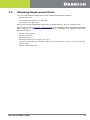
1.6 Obtaining Replacement Parts. . . . . . . . . . . . . . . . . . . . . . . . . . . . . . . . . . . . . . . 13
Chapter 1:Introduction
1.1 Models Covered . . . . . . . . . . . . . . . . . . . . . . . . . . . . . . . . . . . . . . . . . . . . . . . . 16
1.2 Compatibility with Branson Products. . . . . . . . . . . . . . . . . . . . . . . . . . . . . . . . . . 21
1.3 Features of the System. . . . . . . . . . . . . . . . . . . . . . . . . . . . . . . . . . . . . . . . . . . 22
1.4 Power Supply Front Panel Controls . . . . . . . . . . . . . . . . . . . . . . . . . . . . . . . . . . . 25
1.5 Actuator Controls and Indicators . . . . . . . . . . . . . . . . . . . . . . . . . . . . . . . . . . . . 26
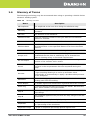
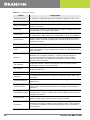
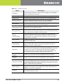
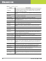
1.6 Glossary of Terms . . . . . . . . . . . . . . . . . . . . . . . . . . . . . . . . . . . . . . . . . . . . . . 27
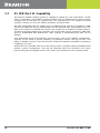
1.7 21 CFR Part 11 Capability . . . . . . . . . . . . . . . . . . . . . . . . . . . . . . . . . . . . . . . . . 36
Chapter 1:Delivery and Handling
1.1 Shipping and Handling . . . . . . . . . . . . . . . . . . . . . . . . . . . . . . . . . . . . . . . . . . . 38
1.2 Receiving . . . . . . . . . . . . . . . . . . . . . . . . . . . . . . . . . . . . . . . . . . . . . . . . . . . . 39
1.3 Unpacking . . . . . . . . . . . . . . . . . . . . . . . . . . . . . . . . . . . . . . . . . . . . . . . . . . . . 40
1.4 Returning Equipment . . . . . . . . . . . . . . . . . . . . . . . . . . . . . . . . . . . . . . . . . . . . 41
Chapter 1:Technical Specifications
1.1 Technical Specifications . . . . . . . . . . . . . . . . . . . . . . . . . . . . . . . . . . . . . . . . . . 44
1.2 Physical Description . . . . . . . . . . . . . . . . . . . . . . . . . . . . . . . . . . . . . . . . . . . . . 47
Chapter 1:Installation and Setup
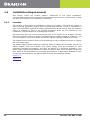
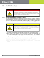
1.1 About Installation. . . . . . . . . . . . . . . . . . . . . . . . . . . . . . . . . . . . . . . . . . . . . . . 52
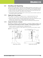
1.2 Handling and Unpacking . . . . . . . . . . . . . . . . . . . . . . . . . . . . . . . . . . . . . . . . . . 53
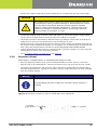
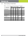
1.3 Take Inventory of Small Parts . . . . . . . . . . . . . . . . . . . . . . . . . . . . . . . . . . . . . . 56
1.4 Installation Requirements . . . . . . . . . . . . . . . . . . . . . . . . . . . . . . . . . . . . . . . . . 58
1.5 Installation Steps . . . . . . . . . . . . . . . . . . . . . . . . . . . . . . . . . . . . . . . . . . . . . . . 66
1.6 Guards and Safety Equipment . . . . . . . . . . . . . . . . . . . . . . . . . . . . . . . . . . . . . . 81
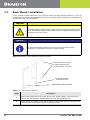
1.7 Rack Mount Installation. . . . . . . . . . . . . . . . . . . . . . . . . . . . . . . . . . . . . . . . . . . 82
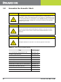
1.8 Assemble the Acoustic Stack . . . . . . . . . . . . . . . . . . . . . . . . . . . . . . . . . . . . . . . 84
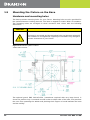
1.9 Mounting the Fixture on the Base. . . . . . . . . . . . . . . . . . . . . . . . . . . . . . . . . . . . 92
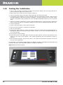
1.10 Testing the Installation . . . . . . . . . . . . . . . . . . . . . . . . . . . . . . . . . . . . . . . . . . . 94
1.11 Still Need Help? . . . . . . . . . . . . . . . . . . . . . . . . . . . . . . . . . . . . . . . . . . . . . . . . 95
Chapter 1:Actuator Operation
1.1 Actuator Controls . . . . . . . . . . . . . . . . . . . . . . . . . . . . . . . . . . . . . . . . . . . . . . . 98
1.2 Initial Actuator Settings . . . . . . . . . . . . . . . . . . . . . . . . . . . . . . . . . . . . . . . . . . 99
1.3 Operating the Actuator . . . . . . . . . . . . . . . . . . . . . . . . . . . . . . . . . . . . . . . . . . 103
1.4 Safety Circuit Alarms . . . . . . . . . . . . . . . . . . . . . . . . . . . . . . . . . . . . . . . . . . . 104
Chapter 1:Maintenance
1.1 Calibration. . . . . . . . . . . . . . . . . . . . . . . . . . . . . . . . . . . . . . . . . . . . . . . . . . . 106
1.2 Periodic and Preventive Maintenance . . . . . . . . . . . . . . . . . . . . . . . . . . . . . . . . 107


100-412-233 REV. 05 EN vi
List of Figure
Chapter 1:Safety and Support
Figure 1.1 Safety label on the rear of the 2000Xc Power Supply . . . . . . . . . . . . . . . . . . . . . . . 3
Figure 1.2 Caution label on the 2000Xc Series Actuator for the factory air supply . . . . . . . . . . . 3
Figure 1.3 Safety label shown on the rear of the 2000Xc Series Actuator . . . . . . . . . . . . . . . . . 3
Figure 1.4 Connector label on the 2000Xc Series Actuator . . . . . . . . . . . . . . . . . . . . . . . . . . . 3
Figure 1.5 Safety Labels on front of the 2000Xc Series Actuator . . . . . . . . . . . . . . . . . . . . . . . 4
Chapter 1:Introduction
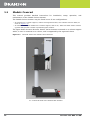
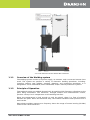
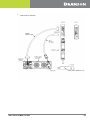
Figure 1.1 Left Side View of the 2000Xc Series Actuator. . . . . . . . . . . . . . . . . . . . . . . . . . . . 16
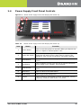
Figure 1.2 2000Xc Power Supply Front Panel Display after Power-Up. . . . . . . . . . . . . . . . . . . 25
Chapter 1:Delivery and Handling
Chapter 1:Technical Specifications
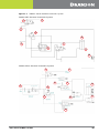
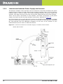
Figure 1.1 2000Xc Series Actuator Pneumatic System . . . . . . . . . . . . . . . . . . . . . . . . . . . . . 49
Chapter 1:Installation and Setup
Figure 1.1 Linear Encoder. . . . . . . . . . . . . . . . . . . . . . . . . . . . . . . . . . . . . . . . . . . . . . . . . 53
Figure 1.2 Unpacking the Stand (Actuator on a Base) . . . . . . . . . . . . . . . . . . . . . . . . . . . . . 54
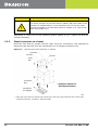
Figure 1.3 Ultrasonic Converter (J-Type for Stand-Alone Use) and Booster. . . . . . . . . . . . . . . 55
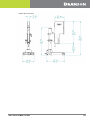
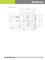
Figure 1.4 Power Supply Dimensional Drawing . . . . . . . . . . . . . . . . . . . . . . . . . . . . . . . . . . 59
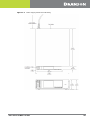
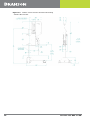
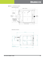
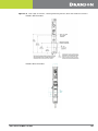
Figure 1.5 2000Xc Series Actuator Dimensional Drawing . . . . . . . . . . . . . . . . . . . . . . . . . . . 60
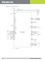
Figure 1.6 Block Wiring Diagram . . . . . . . . . . . . . . . . . . . . . . . . . . . . . . . . . . . . . . . . . . . . 62
Figure 1.7 Base Mounting Centers . . . . . . . . . . . . . . . . . . . . . . . . . . . . . . . . . . . . . . . . . . . 67
Figure 1.8 Rear view of Actuator, showing Mounting Surface, Bolt and Guide Pin locations. . . . 69
Figure 1.9 Electrical Connections from Power Supply to a 2000Xc Series Actuator. . . . . . . . . . 72
Figure 1.10 Start Switch Connection Codes (CE Actuator) . . . . . . . . . . . . . . . . . . . . . . . . . . . 74
Figure 1.11 User I/O Cable Identification and Wire Color Diagram. . . . . . . . . . . . . . . . . . . . . . 76
Figure 1.12 International Harmonized Line Cord Color Code . . . . . . . . . . . . . . . . . . . . . . . . . . 79
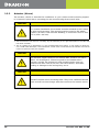
Figure 1.13 Actuator Emergency Stop Button . . . . . . . . . . . . . . . . . . . . . . . . . . . . . . . . . . . . 81
Figure 1.14 Detail of Rack Mount Handle Kit Assembly. . . . . . . . . . . . . . . . . . . . . . . . . . . . . . 82
Figure 1.15 Assembling the 20kHz Acoustic Stack . . . . . . . . . . . . . . . . . . . . . . . . . . . . . . . . 87
Figure 1.16 Connecting Tip to Horn . . . . . . . . . . . . . . . . . . . . . . . . . . . . . . . . . . . . . . . . . . . 88
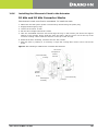
Figure 1.17 Installing a 20kHz Stack in 2000Xc AEC Actuator. . . . . . . . . . . . . . . . . . . . . . . . . 89
Figure 1.18 Installing a 40kHz Stack in 2000Xc AEC Actuator. . . . . . . . . . . . . . . . . . . . . . . . . 90
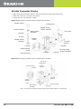
Figure 1.19 Installing a 40kHz Stack in 2000Xc Micro Actuator . . . . . . . . . . . . . . . . . . . . . . . . 90
Figure 1.20 Mounting Holes on Base . . . . . . . . . . . . . . . . . . . . . . . . . . . . . . . . . . . . . . . . . . 92
Figure 1.21 Front Panel Display. . . . . . . . . . . . . . . . . . . . . . . . . . . . . . . . . . . . . . . . . . . . . . 94
Chapter 1:Actuator Operation
Chapter 1:Maintenance

vii 100-412-233 REV. 05 EN

100-412-233 REV. 05 EN viii
List of Tables
Chapter 1:Safety and Support
Table 1.1 Warranty Period. . . . . . . . . . . . . . . . . . . . . . . . . . . . . . . . . . . . . . . . . . . . . . . . . 7
Table 1.2 Branson Contacts. . . . . . . . . . . . . . . . . . . . . . . . . . . . . . . . . . . . . . . . . . . . . . . 12
Chapter 1:Introduction
Table 1.1 2000Xc Series Actuator Compatibility with Branson Converters . . . . . . . . . . . . . . . 21
Table 1.2 2000Xc Power Supply Front Panel Display after Power-Up. . . . . . . . . . . . . . . . . . . 25
Table 1.3 Glossary of Terms . . . . . . . . . . . . . . . . . . . . . . . . . . . . . . . . . . . . . . . . . . . . . . 27
Chapter 1:Delivery and Handling
Table 1.1 Environmental Specifications . . . . . . . . . . . . . . . . . . . . . . . . . . . . . . . . . . . . . . . 38
Table 1.2 Receiving . . . . . . . . . . . . . . . . . . . . . . . . . . . . . . . . . . . . . . . . . . . . . . . . . . . . 39
Table 1.3 Unpacking Procedure . . . . . . . . . . . . . . . . . . . . . . . . . . . . . . . . . . . . . . . . . . . . 40
Chapter 1:Technical Specifications
Table 1.1 Environmental Specifications . . . . . . . . . . . . . . . . . . . . . . . . . . . . . . . . . . . . . . . 44
Table 1.2 Maximum Welding Force (at 100 psig and 4.0” stroke) . . . . . . . . . . . . . . . . . . . . . 45
Table 1.3 Dynamic Trigger Force . . . . . . . . . . . . . . . . . . . . . . . . . . . . . . . . . . . . . . . . . . . 45
Table 1.4 Dynamic Follow-Through. . . . . . . . . . . . . . . . . . . . . . . . . . . . . . . . . . . . . . . . . . 45
Table 1.5 Maximum Traverse Speed (application dependant). . . . . . . . . . . . . . . . . . . . . . . . 46
Table 1.6 Description of Controls on Base . . . . . . . . . . . . . . . . . . . . . . . . . . . . . . . . . . . . . 47
Table 1.7 2000Xc Series Actuator Pneumatic System . . . . . . . . . . . . . . . . . . . . . . . . . . . . . 50
Chapter 1:Installation and Setup
Table 1.1 Small Parts included (=x) with Power Supply and/or Actuator Assemblies. . . . . . . . 56
Table 1.2 List of Cables. . . . . . . . . . . . . . . . . . . . . . . . . . . . . . . . . . . . . . . . . . . . . . . . . . 57
Table 1.3 Environmental Specifications . . . . . . . . . . . . . . . . . . . . . . . . . . . . . . . . . . . . . . . 63
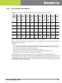
Table 1.4 Cubic Feet of air per minute per inch of stroke length (each direction) . . . . . . . . . . 65
Table 1.5 User I/O Cable Pin Assignments. . . . . . . . . . . . . . . . . . . . . . . . . . . . . . . . . . . . . 77
Table 1.6 User I/O DIP Switch Functions . . . . . . . . . . . . . . . . . . . . . . . . . . . . . . . . . . . . . . 80
Table 1.7 Rack Mount Installation. . . . . . . . . . . . . . . . . . . . . . . . . . . . . . . . . . . . . . . . . . . 82
Table 1.8 Tools, Grease and Mylar Washers. . . . . . . . . . . . . . . . . . . . . . . . . . . . . . . . . . . . 84
Table 1.9 For a 20 kHz System . . . . . . . . . . . . . . . . . . . . . . . . . . . . . . . . . . . . . . . . . . . . 85
Table 1.10 For a 30 kHz System . . . . . . . . . . . . . . . . . . . . . . . . . . . . . . . . . . . . . . . . . . . . 85
Table 1.11 For a 40kHz System . . . . . . . . . . . . . . . . . . . . . . . . . . . . . . . . . . . . . . . . . . . . . 86
Table 1.12 Stud Torque Values . . . . . . . . . . . . . . . . . . . . . . . . . . . . . . . . . . . . . . . . . . . . . 87
Table 1.13 Tip to Horn Torque Specifications. . . . . . . . . . . . . . . . . . . . . . . . . . . . . . . . . . . . 88
Chapter 1:Actuator Operation
Table 1.1 To adjust Mechanical Stop of 2000Xc AEC Actuator . . . . . . . . . . . . . . . . . . . . . . 101
Table 1.2 To adjust Mechanical Stop of 2000Xc Micro Actuator . . . . . . . . . . . . . . . . . . . . . 102
Table 1.3 Operating the Actuator . . . . . . . . . . . . . . . . . . . . . . . . . . . . . . . . . . . . . . . . . . 103
Chapter 1:Maintenance
Table 1.1 Routine Component Replacement. . . . . . . . . . . . . . . . . . . . . . . . . . . . . . . . . . . 110
Table 1.2 Accessories List for 2000Xc Series Actuator. . . . . . . . . . . . . . . . . . . . . . . . . . . . 111

ix 100-412-233 REV. 05 EN

100-412-233 REV. 05 EN 1
Chapter 1: Safety and Support
1.1 Safety Requirements and Warnings . . . . . . . . . . . . . . . . . . . . . . . . . . .2
1.2 General Precautions . . . . . . . . . . . . . . . . . . . . . . . . . . . . . . . . . . . . . . .5
1.3 Warranty Statement, Disclaimer. . . . . . . . . . . . . . . . . . . . . . . . . . . . . .7

2 100-412-233 REV. 05 EN
1.1 Safety Requirements and Warnings
This chapter contains an explanation of the different Safety Notice symbols and icons
found both in this manual and on the product itself and provides additional safety
information for ultrasonic welding. This chapter also describes how to contact Branson for
assistance.
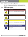
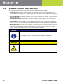
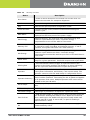
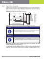
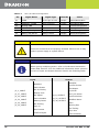
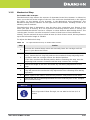
1.1.1 Symbols Found in this Manual
These symbols used throughout this manual warrant special attention:
DANGER High level of risk
If these risks are not avoided, death or severe injury will be the
result.
WARNING Indicates a possible danger
If these risks are not avoided, death or severe injury might result.
CAUTION Low level of risk
If these risks are not avoided, slight or minor injury might result.
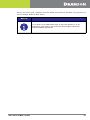
NOTICE Indicates important but non-hazardous information
If this situation is not avoided, the system or something in its vicinity
might be damaged.
Application types and other important or useful information are
emphasized.

100-412-233 REV. 05 EN 3
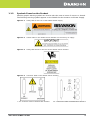
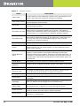
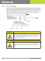
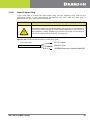
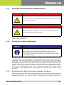
1.1.2 Symbols Found on the Product
Familiar graphic warning symbols are used to alert the user to items of concern or hazard.
The following warning symbols appear on the 2000Xc Series Actuator and Power Supply.
Figure 1.1 Safety label on the rear of the 2000Xc Power Supply
Figure 1.2 Caution label on the 2000Xc Series Actuator for the factory air supply
Figure 1.3 Safety label shown on the rear of the 2000Xc Series Actuator
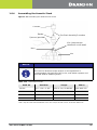
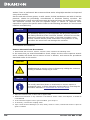
Figure 1.4 Connector label on the 2000Xc Series Actuator
1.4.1 Connector Label of 2000Xc AEC Actuator 1.4.2 Connector Label of 2000Xc Micro Actuato
r

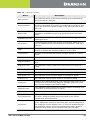
4 100-412-233 REV. 05 EN
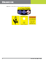
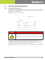
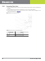
Figure 1.5 Safety Labels on front of the 2000Xc Series Actuator

100-412-233 REV. 05 EN 5
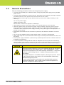
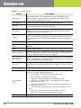
1.2 General Precautions
Take the following precautions before servicing the power supply:
• To prevent the possibility of an electrical shock, always plug the power supply into a grounded
power source.
• To prevent the possibility of an electrical shock, ground the power supply by securing an 8 gauge
grounded conductor to the ground screw located next to the air outlet.
• Power supplies produce high voltage. Before working on the power supply assembly, do the
following:
Turn off the power supply;
Unplug main power; and
Allow at least 2 minutes for capacitors to discharge.
• High voltage is present in the power supply. Do not operate with the cover removed.
• High line voltages exist in the ultrasonic power supply assembly. Common points are tied to
circuit reference, not chassis ground. Therefore, use only non-grounded, battery-powered
multimeters when testing the power supply assembly. Using other types of test equipment can
present a shock hazard.
• Keep hands from under the horn. Down force (pressure) and ultrasonic vibrations can cause
injury.
• Do not cycle the welding system if either the RF cable or converter is disconnected.
• When using larger horns, avoid situations where fingers could be pinched between the horn and
the fixture.
• Ensure power supply installation is performed by qualified personnel and in accordance with local
standards and regulations.
• In normal operation, bearing seals will retain an adequate amount of grease for safe bearing
operation. Bearing can leak but contains enough grease for the life of the bearing. Removing and
running without grease will void the warranty. For more information contact product support.
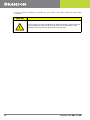
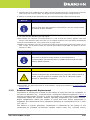
CAUTION
Sound level and frequency of the noise emitted during the ultrasonic
assembly process may depend upon a. type of application, b. size,
shape and composition of the material being assembled, c. shape and
material of the holding fixture, d. welder setup parameters and e.
tool design.
Some parts vibrate at an audible frequency during the process. Some
or all of these factors may result in an uncomfortable noise being
emitted during the process.
In such cases operators may need to be provided with personal
protective equipment. See 29 CFR (Code of Federal Regulations)
1910.95 Occupational Noise Exposure.

6 100-412-233 REV. 05 EN
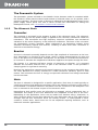
1.2.1 Intended Use of the System
The 2000Xc Series Actuator and components are designed to be used as part of an
ultrasonic welding system. These are designed for a wide variety of welding or processing
applications.
If the equipment is used in a manner not specified by Branson, the protection provided by
the equipment may be impaired.
Branson Ultrasonics Corporation designs and manufactures machines giving the first
priority to safety precautions, to allow customers to use the machines safely and
effectively. Only trained operators should run and service the equipment. Untrained
operators can misuse the equipment or ignore safety instructions that can result in
personal injury or equipment damage. It is most essential that all operators and service
personnel pay attention to safety instructions when operating and servicing the
equipment.
1.2.2 Emissions
Because of the various types of toxic or injurious gases that may be liberated during the
welding based on the material being processed, sufficient ventilation should be provided
to prevent a concentration of these gases in excess of 0.1 ppm. Check with your materials
suppliers for recommended protection when processing their materials.
1.2.3 Setting up the Workplace
Measures for setting up a workplace for safe operation of the ultrasonic welder are
outlined in Chapter 1: Installation and Setup
1.2.4 Regulatory Compliance
This product meets electrical safety requirements and EMC (Electromagnetic Compliance)
requirements for North America and the European Union.
CAUTION
Processing of many materials, such as PVC, can be hazardous to an
operator’s health and could cause corrosion/damage to the
equipment. Use proper ventilation and take protective measures.

100-412-233 REV. 05 EN 7
1.3 Warranty Statement, Disclaimer
The following excerpts from the “Terms and Conditions of Sale” (found on the back of your
Invoice) are essential guidelines for the product Warranty issued with your Branson
ultrasonic welding components. The items listed in this section specifically address issues
involving the delivery, shipment, and warranty period provided. If you have any questions,
please refer to the back of the Invoice included with your system, which lists all of the
Terms and Conditions of Sale, or contact your Branson representative.
TERMS AND CONDITIONS OF SALE
Branson Ultrasonics Corporation is herein referred to as the “Seller” and the customer or
person or entity purchasing products (“Products”) from Seller is referred to as the “Buyer.”
Buyer’s acceptance of the Products will manifest Buyer’s assent to these Terms and
Conditions.
ULTRASONIC JOINING EQUIPMENT NORTH AMERICAN
WARRANTY POLICY
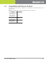
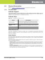
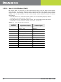
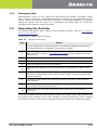
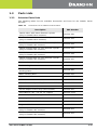
Each product manufactured by Branson is guaranteed to be free from defects in material
and workmanship for a period of time specified in Table 1.1 from the date of shipment.
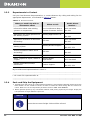
Table 1.1 Warranty Period
Product Period
Power Supplies 36 months
Actuators 36 months
Integrated Welders 36 months
Accessories 36 months
Converters
36 months (limited to one-time
replacement)
Non-Branson equipment Warranted by the manufacturer
Horns
12 months (limited to one-time
replacement)
Boosters 36 months
Handheld devices 12 months
Rental Equipment Same as purchased equipment
Specials and products with EDP
prefix 159-xxx-xxx
12 months
Specials and products with EDP
prefix 125-xxx-xxx
12 months

8 100-412-233 REV. 05 EN
The warranty does not apply to:
• Any product which has been subject to misuse, misapplication, neglect (including without
limitation inadequate maintenance), accident or improper installation, modification or adjustment
• Applications requiring metal-to-metal contact when the ultrasonic exposure time exceeds 1.5
seconds
• Any product exposed to adverse environments, improper repair or repairs using non-Branson
methods or material
• Non-Branson equipment (i.e., horns, boosters, converters) or improperly tuned horns
• Set-up/installation of equipment and software updates
Warranty Service covers the following:
Repair service at Branson’s main repair facility or a regional office.
• Includes parts and labor performed at Branson authorized repair facilities. The customer must
return the equipment properly packed with all shipping charges prepaid
Repair service at the customer site
• Includes parts and labor at the customer site performed by a Branson technician. The customer
is responsible for all travel-related charges
Module trade-in:
• Includes serialized components for work performed by the customer. The customer orders the
replacement components from the Parts Store and issues a P.O. When the failed components are
returned to Branson the warranty status is verified and a credit is issued. The customer is
responsible for all shipping charges
• Additional Warranty Notes
• Components replaced during in-warranty repair carry the remainder of the original warranty
• Serialized assemblies replaced during the repair of out-of-warranty equipment are warranted for
a period of 12 months
• Travel charges for Branson service personnel will be waived on service calls performed within 30
days of invoice date
• Non-serialized parts replaced during the repair of out-of-warranty equipment are warranted for 3
months
• Trade in allowance: Branson out-of-warranty serialized components are entitled to a 25 % trade
in allowance regardless of age or condition, however, converters must be less than 5 years old to
qualify for the trade in
If you have any questions concerning the warranty coverage (including coverage outside
of North America), please contact your Branson representative or Branson Customer
Support.

100-412-233 REV. 05 EN 9
1.4 How to Contact Branson
Branson is here to help you. We appreciate your business and are interested in helping
you successfully use our products. To contact Branson for help, use the following
telephone numbers, or contact the field office nearest you (business hours from 8 a.m. to
4 p.m. Central and Eastern Time Zones):
• North American Headquarters (all Departments): (203) 796-0400
• Parts Store (direct number): (877) 330-0406
• Repair department: (877)-330-0405
• For emergency after-hours service (5 p.m. – 8 a.m. EST): (203) 796-0500 (US phone
numbers only)
Tell the operator which product you have and which person or department you need
(Table 1.1). If after hours, please leave a voice message with your name and return
telephone number.
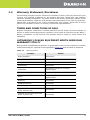
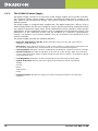
1.4.1 Before Calling Branson for Assistance
This manual provides information for troubleshooting and resolving problems that could
occur with the equipment (see Chapter 1: Maintenance). If you still require assistance,
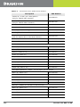
Branson Product Support is here to help you. To help identify the problem, use the
following questionnaire which lists the common questions you will be asked when you
contact the Product Support department.
Before calling, determine the following information:
1. Your company name and location
2. Your return telephone number
3. Have your manual with you. If troubleshooting a problem, refer to
Chapter 1: Maintenance
4. Know your equipment model and serial numbers (found on a gray data label on the units).
Information about the horn (part number, gain, etc.) or other tooling may be etched into the
tooling. Software- or firmware-based systems may provide a BOS or software version number,
which may be required
5. What tooling (horn) and booster are being used?
6. What are the setup parameters and mode?
7. Is your equipment in an automated system? If so, what is supplying the “start” signal?
8. Describe the problem; provide as much detail as possible. For example, is the problem
intermittent? How often does it occur? How long before it occurs if you are just powering up? If
an error is occurring, which error (give error number or name)?
9. List the steps you have already taken
10.What is your application, including the materials being processed?
11.Have a list of service or spare parts you have on hand (tips, horns, etc.)
12.Notes:
____________________________________________________________________________
____________________________________________________________________________
____________________________________________________________________________
____________________________________________________________________________

10 100-412-233 REV. 05 EN
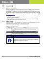
1.5 Returning Equipment for Repair
Before sending equipment for repair, provide as much information with the equipment to
help determine the problem with the system. Use the following page to record necessary
information.
If you are returning equipment to Branson for repair, you must first call the Repair
department to obtain a Returned Goods Authorization (RGA) number. (If you request
it, the repair department will fax a Returned Goods Authorization form to fill out and
return with your equipment).
Branson Repair Department, C/O Zuniga Logistics, LTD
12013 Sara Road, Killam Industrial Park
Laredo, Texas 78045 U.S.A.
Direct telephone number: (877) 330-0405
Fax number: (877) 330-0404
• Provide as much information as possible that will help identify the need for repair.
• Carefully pack the equipment in original packing cartons.
• Clearly label all shipping cartons with the RGA number on the outside of cartons as well as on
your packing slip, along with the reason for return.
• Return general repairs by any convenient method. Send priority repairs by air freight.
• You must prepay the transportation charges FOB Laredo, Texas, U.S.A.
1.5.1 Get an RGA Number
RGA#
_______________________________________________________________________
If you are returning equipment to Branson, please call the Repair Department to obtain a
Returned Goods Authorization (RGA) number. (At your request, the Repair Department
will fax an RGA form to fill out and return with the equipment.)
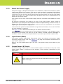
NOTICE
To return equipment to Branson, you must first obtain an RGA
number from a Branson representative, or the shipment may be
delayed or refused.

100-412-233 REV. 05 EN 11
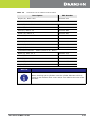
1.5.2 Record Information About the Problem
Before sending equipment for repair, record the following information and send a copy of it
with the equipment. This will greatly increase Branson’s ability to address the problem.
1. Describe the problem; provide as much detail as possible. For example, is the problem
intermittent? How often does it occur? How long before it occurs after powering up?
____________________________________________________________________________
____________________________________________________________________________
____________________________________________________________________________
____________________________________________________________________________
2. Is your equipment in an automated system?
____________________________________________________________________________
____________________________________________________________________________
3. If the problem is with an external signal, which signal?
____________________________________________________________________________
____________________________________________________________________________
4. If known, include plug/pin # (e.g., P29, pin #3) for that signal:
____________________________________________________________________________
____________________________________________________________________________
5. What are the Weld Parameters?
____________________________________________________________________________
____________________________________________________________________________
____________________________________________________________________________
____________________________________________________________________________
What is your application? (Type of weld, plastic material, etc.):
_______________________________________________________________________
_______________________________________________________________________
_______________________________________________________________________
Name and phone number of the person most familiar with the problem:
_______________________________________________________________________
_______________________________________________________________________
_______________________________________________________________________
Contact the Branson office prior to shipping the equipment.
For equipment not covered by warranty, to avoid delay, include a Purchase Order.
Send a copy of this page with the equipment being returned for repair.
Page is loading ...
Page is loading ...
Page is loading ...
Page is loading ...
Page is loading ...
Page is loading ...
Page is loading ...
Page is loading ...
Page is loading ...
Page is loading ...
Page is loading ...
Page is loading ...
Page is loading ...
Page is loading ...
Page is loading ...
Page is loading ...
Page is loading ...
Page is loading ...
Page is loading ...
Page is loading ...
Page is loading ...
Page is loading ...
Page is loading ...
Page is loading ...
Page is loading ...
Page is loading ...
Page is loading ...
Page is loading ...
Page is loading ...
Page is loading ...
Page is loading ...
Page is loading ...
Page is loading ...
Page is loading ...
Page is loading ...
Page is loading ...
Page is loading ...
Page is loading ...
Page is loading ...
Page is loading ...
Page is loading ...
Page is loading ...
Page is loading ...
Page is loading ...
Page is loading ...
Page is loading ...
Page is loading ...
Page is loading ...
Page is loading ...
Page is loading ...
Page is loading ...
Page is loading ...
Page is loading ...
Page is loading ...
Page is loading ...
Page is loading ...
Page is loading ...
Page is loading ...
Page is loading ...
Page is loading ...
Page is loading ...
Page is loading ...
Page is loading ...
Page is loading ...
Page is loading ...
Page is loading ...
Page is loading ...
Page is loading ...
Page is loading ...
Page is loading ...
Page is loading ...
Page is loading ...
Page is loading ...
Page is loading ...
Page is loading ...
Page is loading ...
Page is loading ...
Page is loading ...
Page is loading ...
Page is loading ...
Page is loading ...
Page is loading ...
Page is loading ...
Page is loading ...
Page is loading ...
Page is loading ...
Page is loading ...
Page is loading ...
Page is loading ...
Page is loading ...
Page is loading ...
Page is loading ...
Page is loading ...
Page is loading ...
Page is loading ...
Page is loading ...
Page is loading ...
Page is loading ...
Page is loading ...
Page is loading ...
Page is loading ...
Page is loading ...
Page is loading ...
Page is loading ...
Page is loading ...
Page is loading ...
Page is loading ...
Page is loading ...
Page is loading ...
-
 1
1
-
 2
2
-
 3
3
-
 4
4
-
 5
5
-
 6
6
-
 7
7
-
 8
8
-
 9
9
-
 10
10
-
 11
11
-
 12
12
-
 13
13
-
 14
14
-
 15
15
-
 16
16
-
 17
17
-
 18
18
-
 19
19
-
 20
20
-
 21
21
-
 22
22
-
 23
23
-
 24
24
-
 25
25
-
 26
26
-
 27
27
-
 28
28
-
 29
29
-
 30
30
-
 31
31
-
 32
32
-
 33
33
-
 34
34
-
 35
35
-
 36
36
-
 37
37
-
 38
38
-
 39
39
-
 40
40
-
 41
41
-
 42
42
-
 43
43
-
 44
44
-
 45
45
-
 46
46
-
 47
47
-
 48
48
-
 49
49
-
 50
50
-
 51
51
-
 52
52
-
 53
53
-
 54
54
-
 55
55
-
 56
56
-
 57
57
-
 58
58
-
 59
59
-
 60
60
-
 61
61
-
 62
62
-
 63
63
-
 64
64
-
 65
65
-
 66
66
-
 67
67
-
 68
68
-
 69
69
-
 70
70
-
 71
71
-
 72
72
-
 73
73
-
 74
74
-
 75
75
-
 76
76
-
 77
77
-
 78
78
-
 79
79
-
 80
80
-
 81
81
-
 82
82
-
 83
83
-
 84
84
-
 85
85
-
 86
86
-
 87
87
-
 88
88
-
 89
89
-
 90
90
-
 91
91
-
 92
92
-
 93
93
-
 94
94
-
 95
95
-
 96
96
-
 97
97
-
 98
98
-
 99
99
-
 100
100
-
 101
101
-
 102
102
-
 103
103
-
 104
104
-
 105
105
-
 106
106
-
 107
107
-
 108
108
-
 109
109
-
 110
110
-
 111
111
-
 112
112
-
 113
113
-
 114
114
-
 115
115
-
 116
116
-
 117
117
-
 118
118
-
 119
119
-
 120
120
-
 121
121
-
 122
122
-
 123
123
-
 124
124
-
 125
125
-
 126
126
-
 127
127
-
 128
128
-
 129
129


Branson 100-412-233 2000Xc Series Actuator Rev. 05 Owner's manual
- Type
- Owner's manual
Ask a question and I''ll find the answer in the document
Finding information in a document is now easier with AI
Related papers
-
Branson 100-412-234 2000Xc Power Supply Rev. 06 Owner's manual
-
-
-
-
-
-
-
-
-
Other documents
-
 Vidalite CE1008830 User manual
-
Lightolier Set of (2) Mounting Bars (24" Span), Not for use User manual
-
Winners Only BTB150 Assembly Instructions
-
Abus 500102006006 Datasheet
-
Titan HEAVY DUTY 6 Foot Rectangular Log Rack User manual
-
AVer 26AV-VB342-TVM Installation guide
-
 Hydroworks 8507808 Owner's manual
-
Fairchild 200XLR User manual
-
GE USLT Series Operating instructions
-
Emerson Hy-Line Series Quick start guide

