Page is loading ...

NEOTECHA SAPRO
®
SAMPLING VALVE SV FOR SAMPLING INTO BOTTLES
InstallatIon and MaIntenance InstructIons
© 2017 Emerson. All Rights Reserved.
Before installation these instructions must be fully read and understood
1 GENERAL INFORMATION ON THE
INSTALLATION AND MAINTENANCE
INSTRUCTIONS
These installation and maintenance
instructions contain the information necessary
for safe and correct installation and operation
of the valve in the prescribed manner. If any
difficulties are encountered during installation
or operation which cannot be solved with
the aid of the installation and maintenance
instructions, please contact the supplier/
manufacturer for more information.
These installation and maintenance
instructions comply with the relevant applicable
EN safety standards.
When installing the valve, the operator or
the person responsible for the design of
the installation must ensure that applicable
national regulations are complied with.
The manufacturer reserves all rights to make
technical changes and improvements at any time.
The use of these installation and maintenance
instructions assumes that the user is qualified
to ‘Qualified Personnel’ level.
Operating staff must be given appropriate
training in the operating and maintenance
instructions.
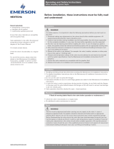
2 SAFETY
Please read these notes carefully.
2.1 General potential danger due to:
a. failure to observe the instructions
b. improper use
c. insufficiently qualified personnel
2.2 Correct use
2.2.1 Area of application
SAPRO sampling valves are valves which
allow a precisely measured sample of highly
corrosive, hot liquids and gases to be taken. A
special feature of the SV is the interchangeable
soft seal, which can be supplied in TFM or
Perfluorelastomer, depending on the medium
used, together with the different body, adaptor
and operating element variants.
The SV is suitable for vertical mounting
and also, subject to certain restrictions, for
horizontal mounting. When the valve is installed
horizontally, it must always be ensured that
the pipe is filled with sufficient medium, so
that a representative sample can be taken.
Furthermore, an angle adaptor must always be
used when the valve is mounted horizontally.
All product-wetted components are
manufactured in PFA/PTFE/TFM materials or in
stainless high-grade steel.
The materials used for components under
pressure are Mat. Nos. 1.4581, 1.0425, 1.4435,
1.4541. Depending on the medium, other
materials, various types of Hastelloy, for
example, can also be used.
Emerson.com/FinalControl VCIOM-01977-EN 18/09
1.1 Validity of the installation and
maintenance instructions
These installation and maintenance
instructions are valid for all SAPRO sampling
valves for sampling into bottles, which have
been manufactured since 28 November 2001 by
the Neotecha AG company. The validity is only
guaranteed until the next revision change!
2.2.2 Method of operation
The valve spindle seals against the sampling
adaptor in the soft seat. When the spindle is
lifted, either by dead man's lever or pneumatic
drive, the spindle opens the outlet and the
medium flows into the sampling vessel. The
air in the container is forced out through a
ventilation hole, and can be either released into
the air or even controlled in another container,
depending on whether the medium constitutes
a danger or not.
When the valve spindle is closed, the SAPRO
sampling valve behaves almost like a
continuous section of pipe, because of the
specially adapted shape of the body. Very low
friction losses and turbulence due to the valve
spindle are to be expected.

2
NEOTECHA SAPRO
®
SAMPLING VALVE SV FOR SAMPLING INTO BOTTLES
InstallatIon and MaIntenance InstructIons
2.2.4 Usage restrictions
The product-wetted components must be
classified as resistant to the product to be
conveyed. Refer to appropriate literature or
consult the manufacturer or distributor for
advice.
2.2.5 Modification prohibition
Mechanical modifications to the valves or the
use of other manufacturers’ parts for repair
purposes are not permissible. Safety is not
guaranteed if this requirement is disregarded.
Repair work must only be carried out by the
manufacturer’s trained personnel.
2.2.6 Warning about foreseeable misuse
Valves and their accessories must not be
misused as climbing aids.
2.2.7 Duty to comply with the instructions for
operation, maintenance and servicing
These operating instructions are part of the
delivery package and must be kept clean and
made accessible to the user.
2.3 Sources of danger
2.3.1 Chemical external
The steel/PFA bodies of the DN65-100 valves
are made from mechanically processed steel
coated with a 2-part polyester paint. The
coating can be attacked externally by strong
solvents, leading to corrosion of the body. If
damage of this nature occurs, the effects on
the environment should be investigated and the
damage to the coating made good.
2.3.2 Electrical
If static charges can lead to explosions, the
valve must be earthed by means of the earthing
accessory.
Alternative: use valves with electrically
conductive linings. Please contact your
supplier!
2.2.3 Performance data
Pressure range: 20 Pa vacuum to 16bar
Temperature range: See diagram
Nominal diameters: DN15-100
Nominal diameters: ANSI Class150 ½” - 4”
Test pressure: 1.5 x PN = 24bar
Pressure
[bar]
20 Pa vacuum
PRESSURE - TEMPERATURE DIAGRAM (VALVE)
Sapro Bellow
PN25
Sapro Bellow
PN16
Sapro SS/PFA
PN16
Temperature
[°C]
Above 200°C only version with
code: SV*****1**A2M**
Version with code: SV*****1**A2M**
only above -5°C
2.3.3 Thermal
Due to the range of operating temperatures
between -20°C and +200°C, surface
temperatures from -20°C to +200°C can
be present on the valve bodies. Suitable
precautions should be taken at the installation
stage to protect against burns due to high or
freezing temperatures. Insulated gloves should
be worn when using the valve.
In case of fire, the mechanical strength of the
PFA coatings is no longer guaranteed above
250°C.
2.3.4 Protection against inadvertent opening of the
sampling valve
The safety pin (Item 3) can be fitted to prevent
unintentional opening of the sampling valve.
This can be additionally secured with a padlock
(Item 10) to guard against willful opening.
2.4 Qualified personnel
This means people who are familiar with the
erection, installation, commissioning, operation
and maintenance of the product and have
appropriate qualifications relating to their
activities and functions, such as, for example:
- Instruction in and duty to comply with all
installation-related, regional and internal
works regulations and requirements.
- Training or instruction in accordance with the
Safety Standards for personal care and use of
appropriate safety equipment and protective
workgear, like, for example, personal
protection equipment (insulated gloves or
similar), suitable for the operating conditions.
Furthermore, these people must have read and
understood these instructions.

3
25 1 4.0 6.5
40 1½ 5.1 8.7
50 2 6.1 10.6
65 2½ 8.7 16.0
80 3 10.0 18.0
100 4 13.7 20.0
NEOTECHA SAPRO
®
SAMPLING VALVE SV FOR SAMPLING INTO BOTTLES
InstallatIon and MaIntenance InstructIons
3 TRANSPORT/STORAGE
The valve is supplied with protective covers.
Do not remove the protective covers until
immediately prior to installation. They protect
the PFA surfaces from dust and mechanical
influences.
3.1 Transport
- Transport temperature -20°C to +65°C.
- Protect against external force (impact, shock,
vibration).
- Do not damage the coating.
4 FEATURES
4.1 General features
Flange drillings DIN2501-1PN16
ANSI B16.5Class150
Other drillings (PN25/40, ANSI Class300) are available on request
Body variants Wafer type
Flanged to DIN standard
Flanged to ANSI standard
Bolted joint A2 bolt quality for all bolts subjected to pressure
Adaptor variants Bottle adaptor for glass threads to ISO GL32/45, customized threads
Bottle cage for increased safety when sampling (breakage of the glass bottle)
Needle adaptor for sampling with bottles which have a septum membrane
Outlet adaptor in various versions
Bottle holder with spring action for various bottle sizes
Special adaptor for aseptic sampling
Bayonet adaptor for sampling with a piston syringe (see NEOJV-0021/VCIOM-01978)
Customized solutions are feasible
Operating element variants
Dead man’s lever for hand operation
Pneumatic drive for full or semi-automatic operation
Piston syringe (the spindle is lifted by the plunger of the piston syringe,
seeNEOJV-0021/VCIOM-01978)
Weights The values given in the following table are only approximate, as the weight can
vary additionally, because of the different adaptor and operating element variants
WEIGHTS
DN NPS Weight compact design Weight flanged face to face
3.2 Storage
- Storage temperature -20°C to +65°C, dry and
dust-free.
- A drying agent or heating is required in damp
storage areas to protect against condensation.
3.3 Handling prior to installation
- Do not remove the protective caps until
immediately prior to installation.
- Protect against the effects of weather, such as
dampness (or else use a drying agent).
- Proper treatment prevents damage.

4
NEOTECHA SAPRO
®
SAMPLING VALVE SV FOR SAMPLING INTO BOTTLES
InstallatIon and MaIntenance InstructIons
4.1.2 Bottle adaptor and sample bottle
- The PTFE bottle adaptor (Item 6) is screwed into the valve body and seals directly on the valve
seat with a Perfluor O-ring.
- The claw (Item 7) secures the bottle adaptor against turning.
- The sample bottle (Item 9) consists mostly of borosilicate glass with a round thread ISO GL45 or
ISO GL32 (DIN168); bottles made of PFA are also available. Bottle sizes: 50 - 1000 ml.
4.2 Installation position
4.1.1 Sampling valve for sampling into bottles
1a. SAPRO sampling valve wafer type face-to-face dimension (DIN/ANSI).
1b. SAPRO sampling valve flanged face-to-face dimension (DIN or ANSI).
2. Dead man’s lever.
3. Safety pin.
4. Grub screw for flow control.
5. Lock nut for fixing the grub screw.
6. Bottle adaptor, standard thread to ISO GL32 or GL45, customized threads are possible.
7. Claw for fixing the bottle adaptor.
8. Tapped vent hole of the bottle adaptor, standard G ¼”.
9. Sampling bottle, borosilicate glass or PFA.
10. Padlock*, to prevent unauthorized opening of the valve.
* Padlock is not included in the delivery package
4.3 Sealing
The sealing of the sampling valve at the bottle adaptor is assured by the soft seat seal; at the
operating element (dead man’s lever), a PTFE sealing ring or a metal bellows is used.
The soft seat seal can be removed with a special tool and replaced (the pipeline must be
depressurized and drained!); in the event that the PTFE sealing ring or the bellows start to leak,
the valve must be removed from the pipeline and sent in to the manufacturer. Leakage past the
sealing ring or the bellows can be safely inspected via the leakage test hole on the upper neck of
the valve, and therefore it is recommended that the yellow plastic screwed plug fitted for shipping
is removed, and replaced, if possible, by screwing in a sensor. Never seal the tapped hole with a
steel screwed plug!
4.2.1 Installing sampling valve for sampling into bottles
The sampling valve for sampling into bottles can only be installed in such a way that the bottle
stands vertically.
For installation in a pipeline running vertically, an angle adaptor must be used (available as an
accessory).

5
NEOTECHA SAPRO
®
SAMPLING VALVE SV FOR SAMPLING INTO BOTTLES
InstallatIon and MaIntenance InstructIons
6.2.1 Step-by-step installation
1. Remove the plastic protective caps.
2. Check the mounting flanges (Items 11 and
12) for damage and soiling.
3. Check that the distance between flanges
matches the face-to-face dimension of the
sampling valve. Before installing the valve
(Items 1a and 1b), spread the flanges apart
sufficiently using a suitable tool.
4. Slide the valve between the opened flanges,
and at the same time insert the packings
(Item D, if required, see Section 6.2.4)
between the sealing surfaces.
5. Now insert the flange bolts through the
adjusting holes.
6. Tighten the flange bolts hand-tight as the
tool holding the flanges apart is gradually
removed. Make sure that the flanges remain
correctly aligned.
7. Tighten all flange bolts in opposite pair
sequence. See Section 6.2.2 for tightening
torques.
8. Connect a vent hose or pipe to the bottle
adaptor vent port (8). The release opening
of the vent hose port shall be placed at a
position where it cannot harm the operator.
6.1.2 Installation position
In accordance with Section 4.2.1 of these
installation and maintenance instructions,
the sampling valve can be installed either
horizontally or vertically, with certain
restrictions (an angle adaptor is required for
horizontal installation).
6.2 Installation in the pipeline
The direction of flow is irrelevant with the
sampling valves. However, before the valve is
installed, a check should be made on whether
any special valve packings are required; for
more information see Section 6.2.3.
An SV valve is not a crowbar! Please do not use
it to force the flanges apart, as this would lead
to damage to the PFA coating and the seat. To
avoid damaging the PFA coating, the protective
covers should only be removed immediately
prior to installation.
WARNING
It is not advisable to use the valves for positioning
pipelines in new systems. Sparks which occur
during spot welding can damage the PFA coating.
Use adjusting pieces instead. Final welding of the
flange with the valve in position will lead to severe
damage to the mounting flange due to the high
temperature.
5 IDENTIFICATION
CE identification on the valve, only if the product falls under the Pressure Equipment Directive
97/23/EC.
Manufacturer
Country of
manufacture
Valve type according to order
details
Serial number
Year of manufacture
CE-mark with number of notified body (onlyrequired
with DN40-100)
6 INSTALLATION
6.1 Installation
6.1.1 Preparation for installation
The dimensions of the valves have been chosen
so that the sampling valves can be clamped
between all current DIN and ANSI flanges.
It should be noted here that sampling valves
designed for a specific flange standard no
longer fit other flanges.
Principal dimensions of the valves: refer to the
catalog page for data.
The flanges must meet the following
requirements:
- Cleaned and undamaged mating surface.
- The mating sections in the pipeline must be
to the same connection standard as the valve
which is to be installed.
- The appropriate flange bolt hole
arrangements in the various flange standards
and diameters allow the valve to be centered
by passing the flange bolts through the holes
in the flanges.
- The flange bolts must be centrally aligned in
the holes in the valve flanges.
Always use all flange bolts, even on low
pressure systems. The valve should never be
pressurized if one of the four flange bolts is
missing.

6
25 1 35 22
40 1½ 60 35
50 2 100 55
65 2½ 130 70
80 3 90 50
100 4 105 60
NEOTECHA SAPRO
®
SAMPLING VALVE SV FOR SAMPLING INTO BOTTLES
InstallatIon and MaIntenance InstructIons
7 COMMISSIONING
6.2.4 Packings
The SAPRO valves are installed and sealed like other valves (ball valves, butterfly valves, etc.).
First of all, take any internal works standards into account and use standard packings.
Depending on the type of pipeline, we recommend the following packings:
SAPRO valve Pipeline type Packing type Packing material
High-grade steel wafer or flanged
style
Steel or high-grade steel with flush flanges Punched flat packing Asbestos-free sheet
Coated flat packing PTFE casing with AFM liner
GORE-TEX flat packing Spun PTFE
PFA coated wafer or flanged style Steel pipe enameled Coated flat packing PTFE casing with steel corrugated ring
Steel PTFE lined No packing
PVDF pipe Punched flat packing EPDM, IIR
Steel pipe rubberized Coated flat packing PTFE casing with AFM liner
Glass pipe with flat surface GORE-TEX flat packing Spun PTFE
6.2.2 Recommended tightening torques (Nm) of bolted connections for installing SAPRO valves
6.2.3 Final checks
Before commissioning the sampling valve, the pipeline should be flushed, to flush out any solid
particles that might be present and which could damage the soft seat of the valve.
The bottle adaptor should also be flushed through at the same time. For this, first remove the
padlock (Item 10, if fitted, not included in delivery package) and pull out the safety pin (Item 3). The
valve can now be opened briefly by pressing the dead man’s lever (Item 2), and then closed again
by releasing the lever.
STANDARD VALUES FOR GALVANIZED STEEL BOLTS (8.8), LIGHTLY OILED
DN NPS Torque high grade steel Torque PFA
7.1 General commissioning
Before commissioning, the information relating
to material, pressure and temperature should
be checked against the installation diagram of
the pipeline system.
Any debris left in the pipeline and valves (dirt,
welding beads, etc.) will inevitably lead to
leakage.
WARNING
Before each commissioning of a new system or
re-commissioning of a system after repair or
modification, it must be ensured that:
- All installation and assembly work has been
completed in accordance with the regulations!
- Commissioning is only undertaken by ‘Qualified
personnel’.
- The valve is in the correct operating position.
- New protective equipment is installed or existing
protective equipment repaired.

7
10 SERVICING AND CLEANING
No routine maintenance or lubrication is
required. However, for systems with high
temperatures, an inspection for leakage at
the flanges should be carried out shortly after
installation. The large difference between the
temperature-related expansions of PFA and
metals can result in cold flow. Tightening the
bolts once again will rectify this problem. This
process may possibly have to be repeated
several times.
WARNING
Before any dismantling or maintenance work is
carried out, the medium in the (depressurized!)
pipeline must be drained off and the pipeline
flushed, so that there is no longer any danger for
the operator/fitter.
When sampling clean, liquid products, no
cleaning is normally required.
In any case, if the bottle adaptor or the seat
assembly of the valve do become soiled
(crystallizing medium), the bottle adaptor can
be dismantled and cleaned as follows:
NEOTECHA SAPRO
®
SAMPLING VALVE SV FOR SAMPLING INTO BOTTLES
InstallatIon and MaIntenance InstructIons
1. Loosen the screw (Item 7) and remove the
claw (Item 7a).
2. The bottle adaptor (Item 6) can now be
unscrewed.
3. Clean the adaptor/seat assembly (Item 1)
and check the upper face of the O-ring; this
must be replaced if defective.
4. Screw the adaptor into the SAPRO body and
secure it with the claw (Items 7, 7a).
Cleaning agents
The cleaning agents recommended by the
internal works department should be used.
Material compatibilities should be checked
before cleaning starts.
7.2 Adjusting the flow quantity
Screw the sampling bottle (Item 9) into the
bottle adaptor (Item 6). Loosen the lock nut
(Item 5). The flow quantity can now be adjusted
to the user’s specific requirement by turning
the grub screw (Item 4) in the desired direction,
and then locking it with the lock nut.
8 NOTES ON DANGERS DURING INSTALLATION,
OPERATION AND MAINTENANCE
Safe operation of the valve is only guaranteed if it
has been correctly installed, commissioned and
maintained by qualified personnel (see ‘Qualified
personnel’), taking into account the warning
information of these installation and maintenance
instructions. In addition, compliance with the
general installation and safety regulations for the
pipeline or plant construction, together with the
correct use of tools and protective equipment,
must be ensured.
WARNING
The installation and maintenance instructions
must be strictly followed when any work is carried
out on the valve or when handling the valve. Non-
observance can result in injuries or damage to
property.
9 OPERATION
Typical sampling:
1. Screw the sample bottle (Item 9) into the
bottle adaptor.
2. Open the padlock (Item 10) and remove the
safety pin.
3. Turn the dead man’s lever (Item 2) anti-
clockwise as far as the preset stop (limit
adjustment, see Section 7.2). This lifts the
valve spindle and the medium flows through
the bottle adaptor into the sample bottle.
4. Watch the sample bottle closely at all times
during filling.
WARNING
The sample bottle must not be overfilled!
5. Release the dead man’s lever when the
required filling quantity is reached. When
the lever is released, it automatically travels
back to the normal position.
6. Unscrew the sample bottle and pass the
sample to the test station.
Socket screw key size 6

8
Neither Emerson, Emerson Automation Solutions, nor any of their affiliated entities assumes responsibility for the selection, use or maintenance of any product.
Responsibility for proper selection, use, and maintenance of any product remains solely with the purchaser and end user.
Neotecha is a mark owned by one of the companies in the Emerson Automation Solutions business unit of Emerson Electric Co. Emerson Automation Solutions, Emerson
and the Emerson logo are trademarks and service marks of Emerson Electric Co. All other marks are the property of their respective owners.
The contents of this publication are presented for informational purposes only, and while every effort has been made to ensure their accuracy, they are not to be
construed as warranties or guarantees, express or implied, regarding the products or services described herein or their use or applicability. All sales are governed by
our terms and conditions, which are available upon request. We reserve the right to modify or improve the designs or specifications of such products at any time without
notice.
Emerson.com/FinalControl
12 DECOMMISSIONING
Removal of the valve for repair or servicing is
often carried out carelessly, as the sampling
valve has to be repaired or replaced in any
case. However, it is recommended that the
valve be removed with care, without damaging
the PFA coating, so that the possible cause of
damage can be determined after removal.
ATTENTION
Check that the pipe is depressurized and drained.
With corrosive, inflammable, aggressive or toxic
media, flush out and ventilate the pipeline system.
1. Only allow assembly work to be carried out
by qualified personnel (see Section 2.4).
2. Loosen all flange bolts and withdraw them
until the valve can be removed.
3. Spread the flanges apart using a suitable
tool and withdraw the valve.
13 DISPOSAL
Hand in the correctly cleaned valve to the scrap
material recycling plant.
WARNING
• Badly cleaned valves can cause severe burning
of the hands and other parts of the body.
• If the sampler is passed on to a third party, the
manufacturer does not guarantee the safety of
the equipment.
NEOTECHA SAPRO
®
SAMPLING VALVE SV FOR SAMPLING INTO BOTTLES
InstallatIon and MaIntenance InstructIons
11 CAUSE AND REMEDY OF OPERATING
FAULTS
If the valve function or operating action is
faulty, a check should be made to ensure that
the assembly and installation work has been
carried out and completed in accordance with
the installation and maintenance instructions.
The information relating to material, pressure,
temperature and direction of flow should be
compared with the installation diagram of the
pipeline system. Furthermore, a check should
be made on whether the installation conditions
correspond to the technical data given in the
data sheet or on the rating plate.
WARNING
The safety regulations must always be observed
when troubleshooting.
/